EP0320065A1 - Tube image couleur - Google Patents
Tube image couleur Download PDFInfo
- Publication number
- EP0320065A1 EP0320065A1 EP88202785A EP88202785A EP0320065A1 EP 0320065 A1 EP0320065 A1 EP 0320065A1 EP 88202785 A EP88202785 A EP 88202785A EP 88202785 A EP88202785 A EP 88202785A EP 0320065 A1 EP0320065 A1 EP 0320065A1
- Authority
- EP
- European Patent Office
- Prior art keywords
- pin
- colour
- shaped member
- angle
- resilient suspension
- Prior art date
- Legal status (The legal status is an assumption and is not a legal conclusion. Google has not performed a legal analysis and makes no representation as to the accuracy of the status listed.)
- Granted
Links
- 239000000725 suspension Substances 0.000 claims abstract description 40
- 238000010894 electron beam technology Methods 0.000 claims description 9
- OAICVXFJPJFONN-UHFFFAOYSA-N Phosphorus Chemical compound [P] OAICVXFJPJFONN-UHFFFAOYSA-N 0.000 claims description 7
- 239000003086 colorant Substances 0.000 claims description 3
- 238000007499 fusion processing Methods 0.000 description 4
- 238000004519 manufacturing process Methods 0.000 description 3
- 238000010276 construction Methods 0.000 description 2
- 230000001419 dependent effect Effects 0.000 description 2
- 230000004927 fusion Effects 0.000 description 2
- 239000011521 glass Substances 0.000 description 2
- 238000003466 welding Methods 0.000 description 2
- 230000002411 adverse Effects 0.000 description 1
- 238000004873 anchoring Methods 0.000 description 1
- 230000002349 favourable effect Effects 0.000 description 1
- 239000000463 material Substances 0.000 description 1
- 238000010008 shearing Methods 0.000 description 1
- 230000035939 shock Effects 0.000 description 1
Images

Classifications
-
- H—ELECTRICITY
- H01—ELECTRIC ELEMENTS
- H01J—ELECTRIC DISCHARGE TUBES OR DISCHARGE LAMPS
- H01J29/00—Details of cathode-ray tubes or of electron-beam tubes of the types covered by group H01J31/00
- H01J29/02—Electrodes; Screens; Mounting, supporting, spacing or insulating thereof
-
- H—ELECTRICITY
- H01—ELECTRIC ELEMENTS
- H01J—ELECTRIC DISCHARGE TUBES OR DISCHARGE LAMPS
- H01J29/00—Details of cathode-ray tubes or of electron-beam tubes of the types covered by group H01J31/00
- H01J29/02—Electrodes; Screens; Mounting, supporting, spacing or insulating thereof
- H01J29/06—Screens for shielding; Masks interposed in the electron stream
- H01J29/07—Shadow masks for colour television tubes
- H01J29/073—Mounting arrangements associated with shadow masks
-
- H—ELECTRICITY
- H01—ELECTRIC ELEMENTS
- H01J—ELECTRIC DISCHARGE TUBES OR DISCHARGE LAMPS
- H01J2229/00—Details of cathode ray tubes or electron beam tubes
- H01J2229/07—Shadow masks
- H01J2229/0722—Frame
Definitions
- the invention relates to a colour display tube comprising an envelope having an electrode system for generating three electron beams, a substantially rectangular display window having an upright edge, which window is provided on the inside with a display screen of phosphor elements luminescing in different colours, a substantially rectangular colour selection electrode which is suspended at a short distance from the display screen and which has a large number of apertures which ensure that each electron beam is directed to phosphor elements of one colour, pin-shaped members having a spherical free end portion are provided in the corners of the upright edge of the display window, resilient suspension elements which are substantially perpendicular to the electron beams to be deflected towards the relevant corner being connected to the colour selection electrode, each resilient suspension element being provided with an at least partly conical portion having an aperture on at least one side of this portion, the spherical free end portion of the relevant pin-shaped member with which the resilient suspension element cooperates engaging in the said aperture, and the spherical free end portion and the conical portion having at least three points of contact.
- Such a colour display tube is known from EP-A1-0240 077. However, it has been found in practice that in a few cases such a colour display tube does not always exhibit a satisfactory colour purity.
- a colour display tube of the type described in the opening paragraph is characterized in that the angle formed by the central axis of the pin-shaped member and a plane extending perpendicularly to the axis of the combination of colour selection electrode and display screen, is larger than an angle at which the resilient suspension element and the associated pin-shaped member contact one another.
- the invention is based on the insight that an unsatisfactory colour purity, as produced sometimes by the known colour display tubes, is caused by the fact that a resilient suspension element lies against the associated pin-shaped member, which is undesirable. Owing to this, the position of the colour selection electrode relative to the display screen is not properly defined which adversely affects the colour purity of the colour display tube.
- the suspension element is prevented from lying against the pin-shaped member, in that the angle formed by the central axis of a pin-shaped member and the said plane is larger than an angle at which a resilient suspension element and the associated pin-shaped member contact one another. Due to this the colour display tube has a satisfactory colour purity.
- a preferred embodiment of a colour display tube according to the invention is characterized in that the central axis of a pin-shaped member forms an angle with the said plane, the central axis of the associated pin-shaped member being at least substantially perpendicular to the upright edge of the display window.
- the upright edge of the display window is not at right angles to the said plane, but instead the normal to the upright edge is at an angle to said plane. Due to the insight gained from the invention, which consists in arranging a pin-shaped member on the upright edge at an angle to a plane, perpendicularly to the axis of the combination of colour selection electrode and display screen, it has become possible to arrange a pin-shaped member substantially perpendicularly to the upright edge.
- the pin-shaped members can be fused into the upright edge. In practice it has proved to be very advantageous to fuse the pinshaped members perpendicularly into the upright edge. In this case only a minimum quantity of glass, from which the upright edge is manufactured, has to be melted, which is advantageous from an enonomical point of view. Moreover, if the pin-shaped members are perpendicularly fused, the force necessary for the fusing operation does not exert a torque on the upright edge. Besides, in the case of a substantially perpendicularly fused pin-shaped member a smaller length of said member than in the case of an obliquely fused pin-shaped member suffices to obtain a proper anchoring in the upright edge. Thus, a saving of material is obtained. To facilitate the fusion of the pin-shaped member, said member should preferably be provided with a shoulder with which the pin-shaped member is pressed into the upright edge.
- thermocompression Another way of providing the pin-shaped member on the upright edge is by means of thermocompression.
- the force required to-provide the pin-shaped member on the upright edge is smaller than in the case of fusing. Consequently, a pin-shaped member which is provided on the upright edge by means of thermocompression need not be provided with a shoulder. To preclude shearing of the pin-shaped members during their provision by thermocompression, it is particularly advantageous to provide them perpendicularly to the upright edge.
- a further embodiment of a very suitable colour display tube according to the invention is characterized in that the conical portion is a separate portion which is located in the aperture of the resilient element, and the conical portion is permanently secured to the associated spherical free end portion and the resilient suspension element, and the central axis of the pin-shaped member forms an angle of at least 5° with the plane. Due to the fact that the pin-shaped members are provided on the upright edge the angle, preferably, does not exceed 20°. This construction does not only provide a colour display tube having a satisfactory colour purity but also a readily conceivable and accurate way of suspending the colour selection electrode in the display window by permanently securing the conical portion to the spherical free end portion.
- An alternative embodiment of a colour display tube according to the invention, in which permanent securing is superfluous is characterized in that the aperture of the conical portion of the resilient suspension element is surrounded by an upright edge whose smallest inside diameter is smaller than the largest outside diameter of the associated spherical free end portion, and in that the central axis of the pin-shaped member forms an angle of at least 9° with the plane. Due to the provision of the pin-shaped members on the upright edge, the angle, preferably, does not exceed 20°.
- Fig. 1 is a sectional view of a colour display tube according to the invention.
- the colour display tube comprises an envelope 1 having a substantially rectangular display window 2 with an upright edge 3.
- the colour display tube further comprises a cone 4 and a neck 5.
- a display screen 6 of phosphor elements luminescing in different colours is provided on the display window 2.
- a substantially rectangular colour selection electrode 7 having a large number of apertures is suspended at a short distance from the display window 2 by means of suspension means 8 which are located near the corners of the said upright edge 3.
- An electrode system 9 for generating three electron beams 10, 11 and 12 is mounted in the neck 5 of the colour display tube. These beams are deflected by a coil system 13.
- the apertures of the colour selection electrode 7 are arranged relative to the luminescing phosphor elements, such that they direct each electron beam to phosphor elements of one colour. Consequently, it can be said that the colour selection electrode 7 and the display screen 6 belong together and form a combination.
- Fig. 2 is a front view of the display window 2 comprising the colour selection electrode 7 which has a large number of apertures 14, viewed from the electrode system.
- Fig. 2 depicts the x-axis and the y-axis and the diagonals D1 and D2 in a way which is known to those skilled in the field of display tubes.
- the axis of the combination of colour selection electrode 7 and display screen (not shown in Fig. 2) is perpendicular to the plane formed by the x-axis and the y-axis and traverses the point of intersection of the x-axis and the y-axis.
- the colour selection electrode 7 is suspended in the display window 2 by means of suspension means 8 which are located where the diagonals D1 and D2 intersect the upright edge 3 of the display window 2.
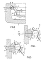
- Each suspension means 8 comprises a resilient suspension element 21 which is secured to the colour selection electrode 7, and a pin-shaped member 15 which is arranged in the corner of the upright edge 3.
- a pin-shaped member is to be understood to mean herein a supporting member having one end portion which can suitably be used for providing the member in the upright edge, and another end portion which can suitably be used for carrying a resilient suspension element (see Fig. 3).
- Fig. 3 is a sectional view of a part of a colour display tube according to the invention, viewed from the direction of the arrows shown in Fig. 2.
- the pin-shaped member 15 has a spherical free end portion 16 and a shoulder 23. Thanks to the shoulder 23 the pin-shaped member 15 can be pressed more readily into the upright edge, which is necessary during the fusion operation.
- the colour selection electrode 7 consists of a thin mask sheet 17 which has a large number of apertures 14 and which is provided with an upright edge 18. A mask edge 19 is attached to the upright edge 18, which mask edge is provided at its corner with a supporting strip 20.
- the resilient suspension element which in the present example is a flat resilient suspension element 21, is secured to this supporting strip 20.
- the flat resilient suspension element 21 forms an angle with the axis of the combination of colour selection electrode 7 and display screen 6, which axis extends perpendicularly to the X-Y plane (in Fig. 3 shown as X-Y), such that the resilient suspension element is substantially perpendicular to the electron beams which are to be deflected towards the relevant corner of the display window 2.
- the flat resilient suspension element 21 comprises a partly conical portion 22.
- the portion 22 of the flat resilient suspension element has an aperture 25 in which the spherical free end portion 16 of the pin-shaped member 15 engages.
- the conical portion 22 may have, for example, a triangular or, in an alternative embodiment, a circular cross-section.
- the rigidity of the construction is increased in that, dependent upon the cross-section of the conical portion 22, the spherical free end portion 16 and the conical portion 22 have at least three points of contact. Moreover, due to the points of contact the conical portion 22 is centred relative to the spherical free end portion.
- a projecting edge 31 is required to form the conical portion 22 in the flat resilient suspension element 21.
- the central axis of the pin-shaped member 15 forms a predetermined angle with the X-Y plane. This is explained in more detail in Fig.
- the central axis A of the pin-shaped member 15 preferably forms an angle a of at least 5° with the X-Y plane to make sure that the projecting edge 31 of the flat resilient suspension element 21 is clear of the pin-shaped member 15. It has been found in practice that due to tolerances caused during, for example, the manufacture of the pin-shaped member and during fusing, the projecting edge 31 may come to lie against, for example, the shoulder 23 of the pinshaped member 15 if the angle ⁇ is smaller than 5°.
- the central axis A of the pin-shaped member 15 is perpendicular to the upright edge 3 of the display window.
- Perpendicularly fusing the pin-shaped member 15 into the upright edge 3 has advantages as regards the fusion process. For example, in comparison with oblique fusing only a minimal quantity of glass has to be melted, which leads to a rapid and inexpensive fusion process. If the angle ⁇ exceeds 20°, the fusion process becomes less advantageous from an economical point of view. Moreover, in the case of perpendicularly fusing a pin-shaped member a smaller length of the member is required than in the case of an obliquely fused pin-shaped member.
- the conical portion 22 is a separate portion 32 which engages in an aperture 33 of the flat resilient suspension element 21.
- this separate portion 32 is secured to the flat resilient suspension element, for example, by means of laser spot welding, after the colour selection electrode has been accurately suspended in the display window.
- a few welds are indicated by means of reference numeral 34.
- the projecting edge 31 is a suitable place for obtaining a proper weld.
- the colour display tube is subjected to further processing, for example, the display window is provided with a display screen.
- the conical portion 22 is secured to the spherical free end portion 16 of the pin-shaped member, for example, by means of laser welding.
- the pin-shaped member 15 Since the free end portion of the pin-shaped member 15 is spherical, the orientation of the conical portion 22 of the flat resilient suspension element 21 relative to the pin-shaped member has no influence. Consequently, the pin-shaped member 15 can be provided on the upright edge 3 at the most favourable angle.
- Fig. 5 shows an alternative embodiment of a colour display tube according to the invention, in which the conical portion 22 is not welded to the spherical free end portion 16.
- the aperture of the conical portion 22 is surrounded by an upright edge 35 having a smallest inside diameter which is smaller than the largest outside diameter of the associated spherical free end portion 16.
- the central axis A preferably forms an angle ⁇ of at least 9° with the X-Y plane. Due to the tolerance caused during the manufacture of the upright edge 35, it has been found in practice that an angle ⁇ smaller than 9° can lead to contact. An angle ⁇ larger than 20° is less economical and less desirable for the fusion process.
Landscapes
- Cathode-Ray Tubes And Fluorescent Screens For Display (AREA)
- Electrodes For Cathode-Ray Tubes (AREA)
- Processing Of Color Television Signals (AREA)
- Color Television Systems (AREA)
Priority Applications (1)
| Application Number | Priority Date | Filing Date | Title |
|---|---|---|---|
| AT88202785T ATE95948T1 (de) | 1987-12-11 | 1988-12-05 | Farbfernsehbildroehre. |
Applications Claiming Priority (2)
| Application Number | Priority Date | Filing Date | Title |
|---|---|---|---|
| NL8702993A NL8702993A (nl) | 1987-12-11 | 1987-12-11 | Kleurenbeeldbuis. |
| NL8702993 | 1987-12-11 |
Publications (2)
| Publication Number | Publication Date |
|---|---|
| EP0320065A1 true EP0320065A1 (fr) | 1989-06-14 |
| EP0320065B1 EP0320065B1 (fr) | 1993-10-13 |
Family
ID=19851075
Family Applications (1)
| Application Number | Title | Priority Date | Filing Date |
|---|---|---|---|
| EP88202785A Expired - Lifetime EP0320065B1 (fr) | 1987-12-11 | 1988-12-05 | Tube image couleur |
Country Status (7)
| Country | Link |
|---|---|
| US (1) | US4987337A (fr) |
| EP (1) | EP0320065B1 (fr) |
| JP (1) | JP2858577B2 (fr) |
| KR (1) | KR970011869B1 (fr) |
| AT (1) | ATE95948T1 (fr) |
| DE (1) | DE3884920T2 (fr) |
| NL (1) | NL8702993A (fr) |
Cited By (4)
| Publication number | Priority date | Publication date | Assignee | Title |
|---|---|---|---|---|
| WO2001039240A1 (fr) * | 1999-11-26 | 2001-05-31 | Koninklijke Philips Electronics N.V. | Tube d'afficheur couleur a suspension amelioree de l'electrode de selection des couleurs |
| WO2001084588A1 (fr) * | 2000-05-02 | 2001-11-08 | Koninklijke Philips Electronics N.V. | Tube couleur a suspension amelioree de l'electrode de selection de couleurs |
| WO2001086686A1 (fr) * | 2000-05-11 | 2001-11-15 | Koninklijke Philips Electronics N.V. | Tube d'affichage couleur avec suspension amelioreee de l'electrode de selection de couleur |
| WO2003054906A3 (fr) * | 2001-12-20 | 2003-09-25 | Koninkl Philips Electronics Nv | Procede permettant de produire une plaque de verre d'un tube d'affichage couleur comprenant des axes de suspension |
Families Citing this family (3)
| Publication number | Priority date | Publication date | Assignee | Title |
|---|---|---|---|---|
| US5256941A (en) * | 1990-06-29 | 1993-10-26 | U.S. Philips Corporation | Color display tube having a suspension means for a color selection electrode |
| US6518694B1 (en) | 1999-09-15 | 2003-02-11 | Osram Sylvania Inc. | Stud for cathode ray tube face panel |
| US6650037B1 (en) * | 2002-05-20 | 2003-11-18 | Thomson Licensing S.A. | Shock absorbing stud shim for a CRT |
Citations (3)
| Publication number | Priority date | Publication date | Assignee | Title |
|---|---|---|---|---|
| US4387321A (en) * | 1980-07-21 | 1983-06-07 | U.S. Philips Corporation | Color display tube and suspension means for color selection electrode |
| EP0156362A2 (fr) * | 1984-03-28 | 1985-10-02 | Nokia Unterhaltungselektronik (Deutschland) GmbH | Tube-image couleur |
| EP0240077A1 (fr) * | 1986-04-02 | 1987-10-07 | Koninklijke Philips Electronics N.V. | Tube image couleur |
Family Cites Families (2)
| Publication number | Priority date | Publication date | Assignee | Title |
|---|---|---|---|---|
| DE3435891A1 (de) * | 1984-09-29 | 1986-04-10 | Standard Elektrik Lorenz Ag, 7000 Stuttgart | Farbbildroehre |
| NL8700984A (nl) * | 1987-04-27 | 1988-11-16 | Philips Nv | Kleurenbeeldbuis met samengesteld ophangmiddel voor kleurselektie elektrode en werkwijze ter vervaardiging van kleurenbeeldbuis. |
-
1987
- 1987-12-11 NL NL8702993A patent/NL8702993A/nl not_active Application Discontinuation
-
1988
- 1988-12-05 AT AT88202785T patent/ATE95948T1/de not_active IP Right Cessation
- 1988-12-05 EP EP88202785A patent/EP0320065B1/fr not_active Expired - Lifetime
- 1988-12-05 DE DE88202785T patent/DE3884920T2/de not_active Expired - Fee Related
- 1988-12-08 KR KR1019880016296A patent/KR970011869B1/ko not_active Expired - Fee Related
- 1988-12-09 JP JP63310216A patent/JP2858577B2/ja not_active Expired - Fee Related
- 1988-12-12 US US07/282,670 patent/US4987337A/en not_active Expired - Fee Related
Patent Citations (3)
| Publication number | Priority date | Publication date | Assignee | Title |
|---|---|---|---|---|
| US4387321A (en) * | 1980-07-21 | 1983-06-07 | U.S. Philips Corporation | Color display tube and suspension means for color selection electrode |
| EP0156362A2 (fr) * | 1984-03-28 | 1985-10-02 | Nokia Unterhaltungselektronik (Deutschland) GmbH | Tube-image couleur |
| EP0240077A1 (fr) * | 1986-04-02 | 1987-10-07 | Koninklijke Philips Electronics N.V. | Tube image couleur |
Cited By (4)
| Publication number | Priority date | Publication date | Assignee | Title |
|---|---|---|---|---|
| WO2001039240A1 (fr) * | 1999-11-26 | 2001-05-31 | Koninklijke Philips Electronics N.V. | Tube d'afficheur couleur a suspension amelioree de l'electrode de selection des couleurs |
| WO2001084588A1 (fr) * | 2000-05-02 | 2001-11-08 | Koninklijke Philips Electronics N.V. | Tube couleur a suspension amelioree de l'electrode de selection de couleurs |
| WO2001086686A1 (fr) * | 2000-05-11 | 2001-11-15 | Koninklijke Philips Electronics N.V. | Tube d'affichage couleur avec suspension amelioreee de l'electrode de selection de couleur |
| WO2003054906A3 (fr) * | 2001-12-20 | 2003-09-25 | Koninkl Philips Electronics Nv | Procede permettant de produire une plaque de verre d'un tube d'affichage couleur comprenant des axes de suspension |
Also Published As
| Publication number | Publication date |
|---|---|
| EP0320065B1 (fr) | 1993-10-13 |
| JP2858577B2 (ja) | 1999-02-17 |
| US4987337A (en) | 1991-01-22 |
| DE3884920T2 (de) | 1994-04-14 |
| JPH01187739A (ja) | 1989-07-27 |
| KR970011869B1 (ko) | 1997-07-18 |
| NL8702993A (nl) | 1989-07-03 |
| KR890010990A (ko) | 1989-08-11 |
| ATE95948T1 (de) | 1993-10-15 |
| DE3884920D1 (de) | 1993-11-18 |
Similar Documents
| Publication | Publication Date | Title |
|---|---|---|
| US4644222A (en) | Color picture tube with mounting structure for a shadow mask | |
| EP0320065A1 (fr) | Tube image couleur | |
| EP0332262A1 (fr) | Procédé pour la réalisation d'un tube à rayons cathodiques couleur et tube à rayons cathodiques couleur | |
| US4763039A (en) | Color display tube with corner suspension means | |
| CN1018491B (zh) | 具有改进荫罩——框架组件支撑的彩色阴极射线管 | |
| KR900002902B1 (ko) | 칼라 표시관 | |
| EP0295732B1 (fr) | Méthode de fabrication d'un canon à électrons | |
| US4605878A (en) | Supporting device for an electron beam landing position selecting mask of a color cathode ray tube | |
| EP0289090A1 (fr) | Tube à rayons cathodiques | |
| EP0289079B1 (fr) | Tube image couleur comportant un élément de suspension en plusieurs parties pour une électrode de sélection de couleur et méthode de fabrication | |
| EP0453039B1 (fr) | Tube à rayons cathodiques muni d'un canon à électrons | |
| EP0487139B1 (fr) | Tube image couleur muni d'un canon à électrons en ligne | |
| CA1275689C (fr) | Methode de fabrication de tubes cathodiques d'affichage d'images en couleurs et tube cathodique d'affichage d'images en couleurs | |
| EP0397470A2 (fr) | Tube image couleur avec un canon à rayons cathodiques contenant une électrode ayant des moyens de fixation optimisés | |
| KR20040005907A (ko) | 음극선관용 마스크 스트랜드 간격의 균일성을 유지하는방법 및 장치 | |
| US4950941A (en) | Color picture tube having improved shadow mask-frame assembly support | |
| US6677701B2 (en) | Stem for cathode ray tube | |
| KR100466681B1 (ko) | 개선된새도우마스크프레임어셈블리지지체를구비한컬러수상관 | |
| JP2980717B2 (ja) | 陰極線管用抵抗体、この抵抗体を用いた電子銃および陰極線管 | |
| KR200160917Y1 (ko) | 컬러 음극선관용 전자총 | |
| JPH07120511B2 (ja) | カラー映像管 | |
| JPH03152833A (ja) | カラー陰極線管用電子銃 | |
| CN1589488A (zh) | 阴极射线管荫罩框架组件 | |
| KR20000074555A (ko) | 진동저감 기능을 갖는 평면 브라운관 | |
| JPH10302661A (ja) | カラー陰極線管の色選別機構の支持スプリング |
Legal Events
| Date | Code | Title | Description |
|---|---|---|---|
| PUAI | Public reference made under article 153(3) epc to a published international application that has entered the european phase |
Free format text: ORIGINAL CODE: 0009012 |
|
| AK | Designated contracting states |
Kind code of ref document: A1 Designated state(s): AT DE FR GB IT NL |
|
| 17P | Request for examination filed |
Effective date: 19891204 |
|
| 17Q | First examination report despatched |
Effective date: 19910719 |
|
| GRAA | (expected) grant |
Free format text: ORIGINAL CODE: 0009210 |
|
| AK | Designated contracting states |
Kind code of ref document: B1 Designated state(s): AT DE FR GB IT NL |
|
| PG25 | Lapsed in a contracting state [announced via postgrant information from national office to epo] |
Ref country code: IT Free format text: LAPSE BECAUSE OF FAILURE TO SUBMIT A TRANSLATION OF THE DESCRIPTION OR TO PAY THE FEE WITHIN THE PRE;WARNING: LAPSES OF ITALIAN PATENTS WITH EFFECTIVE DATE BEFORE 2007 MAY HAVE OCCURRED AT ANY TIME BEFORE 2007. THE CORRECT EFFECTIVE DATE MAY BE DIFFERENT FROM THE ONE RECORDED.SCRIBED TIME-LIMIT Effective date: 19931013 Ref country code: AT Effective date: 19931013 Ref country code: NL Effective date: 19931013 |
|
| REF | Corresponds to: |
Ref document number: 95948 Country of ref document: AT Date of ref document: 19931015 Kind code of ref document: T |
|
| REF | Corresponds to: |
Ref document number: 3884920 Country of ref document: DE Date of ref document: 19931118 |
|
| ET | Fr: translation filed | ||
| NLV1 | Nl: lapsed or annulled due to failure to fulfill the requirements of art. 29p and 29m of the patents act | ||
| PLBE | No opposition filed within time limit |
Free format text: ORIGINAL CODE: 0009261 |
|
| STAA | Information on the status of an ep patent application or granted ep patent |
Free format text: STATUS: NO OPPOSITION FILED WITHIN TIME LIMIT |
|
| 26N | No opposition filed | ||
| REG | Reference to a national code |
Ref country code: FR Ref legal event code: CD |
|
| REG | Reference to a national code |
Ref country code: FR Ref legal event code: CD |
|
| REG | Reference to a national code |
Ref country code: GB Ref legal event code: IF02 |
|
| REG | Reference to a national code |
Ref country code: GB Ref legal event code: 746 Effective date: 20020919 |
|
| REG | Reference to a national code |
Ref country code: FR Ref legal event code: D6 |
|
| PGFP | Annual fee paid to national office [announced via postgrant information from national office to epo] |
Ref country code: FR Payment date: 20021223 Year of fee payment: 15 |
|
| PGFP | Annual fee paid to national office [announced via postgrant information from national office to epo] |
Ref country code: GB Payment date: 20021224 Year of fee payment: 15 |
|
| PGFP | Annual fee paid to national office [announced via postgrant information from national office to epo] |
Ref country code: DE Payment date: 20030217 Year of fee payment: 15 |
|
| PG25 | Lapsed in a contracting state [announced via postgrant information from national office to epo] |
Ref country code: GB Free format text: LAPSE BECAUSE OF NON-PAYMENT OF DUE FEES Effective date: 20031205 |
|
| PG25 | Lapsed in a contracting state [announced via postgrant information from national office to epo] |
Ref country code: DE Free format text: LAPSE BECAUSE OF NON-PAYMENT OF DUE FEES Effective date: 20040701 |
|
| GBPC | Gb: european patent ceased through non-payment of renewal fee |
Effective date: 20031205 |
|
| PG25 | Lapsed in a contracting state [announced via postgrant information from national office to epo] |
Ref country code: FR Free format text: LAPSE BECAUSE OF NON-PAYMENT OF DUE FEES Effective date: 20040831 |
|
| REG | Reference to a national code |
Ref country code: FR Ref legal event code: ST |