EP0320073B1 - Faisceau de canons à air - Google Patents
Faisceau de canons à air Download PDFInfo
- Publication number
- EP0320073B1 EP0320073B1 EP88202806A EP88202806A EP0320073B1 EP 0320073 B1 EP0320073 B1 EP 0320073B1 EP 88202806 A EP88202806 A EP 88202806A EP 88202806 A EP88202806 A EP 88202806A EP 0320073 B1 EP0320073 B1 EP 0320073B1
- Authority
- EP
- European Patent Office
- Prior art keywords
- array
- frequency
- guns
- gun
- seismic
- Prior art date
- Legal status (The legal status is an assumption and is not a legal conclusion. Google has not performed a legal analysis and makes no representation as to the accuracy of the status listed.)
- Expired - Lifetime
Links
- 238000000034 method Methods 0.000 claims description 46
- 238000001228 spectrum Methods 0.000 claims description 32
- 239000002131 composite material Substances 0.000 claims description 12
- XLYOFNOQVPJJNP-UHFFFAOYSA-N water Substances O XLYOFNOQVPJJNP-UHFFFAOYSA-N 0.000 claims description 4
- 239000002360 explosive Substances 0.000 claims description 3
- 230000035939 shock Effects 0.000 claims description 2
- 238000003491 array Methods 0.000 description 18
- 230000010355 oscillation Effects 0.000 description 6
- 230000000694 effects Effects 0.000 description 4
- 230000003993 interaction Effects 0.000 description 4
- 238000005259 measurement Methods 0.000 description 4
- 238000004088 simulation Methods 0.000 description 4
- 238000007796 conventional method Methods 0.000 description 3
- 238000013461 design Methods 0.000 description 3
- 230000015572 biosynthetic process Effects 0.000 description 2
- 238000004422 calculation algorithm Methods 0.000 description 2
- 238000005755 formation reaction Methods 0.000 description 2
- 238000012986 modification Methods 0.000 description 2
- 230000004048 modification Effects 0.000 description 2
- 230000004044 response Effects 0.000 description 2
- 238000012360 testing method Methods 0.000 description 2
- 230000005534 acoustic noise Effects 0.000 description 1
- 230000001174 ascending effect Effects 0.000 description 1
- 230000005540 biological transmission Effects 0.000 description 1
- 238000004364 calculation method Methods 0.000 description 1
- 230000008859 change Effects 0.000 description 1
- 230000008602 contraction Effects 0.000 description 1
- 230000003247 decreasing effect Effects 0.000 description 1
- 230000001419 dependent effect Effects 0.000 description 1
- 230000007613 environmental effect Effects 0.000 description 1
- 238000002474 experimental method Methods 0.000 description 1
- 230000002706 hydrostatic effect Effects 0.000 description 1
- 230000006872 improvement Effects 0.000 description 1
- 238000012804 iterative process Methods 0.000 description 1
- 238000013507 mapping Methods 0.000 description 1
- 230000035515 penetration Effects 0.000 description 1
- 230000000704 physical effect Effects 0.000 description 1
- 230000010399 physical interaction Effects 0.000 description 1
- 238000000926 separation method Methods 0.000 description 1
- 230000003595 spectral effect Effects 0.000 description 1
- 238000012421 spiking Methods 0.000 description 1
Images



Classifications
-
- G—PHYSICS
- G01—MEASURING; TESTING
- G01V—GEOPHYSICS; GRAVITATIONAL MEASUREMENTS; DETECTING MASSES OR OBJECTS; TAGS
- G01V1/00—Seismology; Seismic or acoustic prospecting or detecting
- G01V1/003—Seismic data acquisition in general, e.g. survey design
- G01V1/006—Seismic data acquisition in general, e.g. survey design generating single signals by using more than one generator, e.g. beam steering or focusing arrays
Definitions
- This invention relates to seismic exploration, and more particularly, relates to marine seismic sources.
- an air gun system In marine seismic exploration an air gun system is normally used as a seismic source in conjunction with a streamer towed behind a seismic exploration vessel.
- the streamer cable normally contains compressional detectors.
- Each air gun suddenly releases high pressure air, which generates compressional energy that is radiated in all directions, with some energy directed towards the sea floor and some towards the sea surface.
- the detectors being towed behind the seismic exploration vessel may detect this radiated energy when it is reflected from formation interfaces below the sea floor.
- the detectors will also detect acoustical noise and direct arrivals from the air gun source, which are not reflected off formations beneath the seafloor but have radiated directly to the detectors, or have been reflected from the sea surface, or sea bottom.
- the minimum volume used is determined by an acceptable pulse spectrum.
- a major component of the radiated signal is caused by bubble oscillations, with the consequence that the composite frequency spectra has peaks and notches.
- these oscillations are often objectionable in both structural and detail mapping, they may be acceptably suppressed by spiking deconvolution and in theory are completely removed by signature deconvolution.
- the deconvolution procedure is very effective in a very noise-free system.
- this good deconvolution performance can not be expected on a seismic trace acquired in a "noisy" marine environment where the noise is larger than the signal in a "notch" of the array spectra.
- U.S.-A-4,382,486 teaches a method for determining the spacing and volume of air guns in a tuned air gun array.
- this reference teaches determining volume ratios (that are calculated based upon a predetermined maximum volume ratio) for any individual gun, with these guns spaced for optimum air gun interaction.
- This reference teaches a particular equation which establishes these volume ratios and determines different gun volumes having bubble periods distributed over a range of times, i.e. T min (minimum bubble period) to T max (maximum bubble period), but with closer spacing between bubble periods near T min .
- This equation includes two parameters which may be varied to provide different array volume ratios; however, this reference is not clear in its teachings of how to optimize these two parameters.
- U.S. Patent Specification No. 4,382,486 teaches selecting the smallest air gun volume, and correspondingly the smallest bubble period (which then determines the highest frequency of his array) and then multiplies this smallest bubble period (highest frequency) by two to obtain an approximation of the bubble period (frequency) for the largest gun.
- twice the bubble period of the smallest gun then has a ghost period subtracted from it to actually determine the bubble period of the largest gun.
- this is equivalent to selecting the largest gun volume, increasing the bubble period of the largest gun by a ghost period and then halving the result to determine the smallest bubble period, from which the smallest gun volume may be determined.
- US 4,382,486 in its broadest claim, starts by selecting the largest air gun volume (without reference to the smallest air gun, a ghost period, or bubble period) followed by selecting the number of air guns to be contained in his array. US 4,382,486 then determines the gun volume ratios for the individual guns based upon the equation, which uses the largest to smallest gun volume ratio (V Ro ). A dependent claim adds the determination of the largest air gun volume from the volume of the smallest air gun, the bubble period of the smallest air gun, and a ghost period.
- Nooteboom teaches the use of bubble periods to calculate air gun volumes, it also suggests the use of a one octave range of frequencies for less than eight guns in an array, and more than one octave range of frequencies for more than eight guns in an array.
- Nooteboom proposes a T max ⁇ 2T min and a bubble period spacing between guns, ⁇ T, of cT2.
- Nooteboom employs an iterative type equation to solve for gun bubble periods once one gun bubble period is known. Further, Nooteboom states that the amplitude of a gun is proportional to its volume.
- methods are provided for determining marine seismic source arrays which operate as broad-band high energy sources.
- the method of the present invention selects a maximum gun size which then determines the minimum or lowest frequency of the array. Alternatively, the lowest frequency may be selected which then determines the largest gun size for a selected operating pressure and depth.
- the number of guns remaining in the array is then selected.
- the remaining number of guns is then used to fill in the first octave from the minimum frequency in a manner to provide a composite amplitude that is as flat as possible over the first octave.
- the method of the present invention utilizes the fact that the amplitude of an individual gun measured far from the gun is inversely proportional to the frequency of the gun.
- the methods of the present invention adjust the frequency difference between the high frequency guns to compensate for their decrease in amplitude.
- Fig. 1 depicts a typical time signature and frequency spectrum for a single air gun.
- the upper horizontal axis represents time (in milliseconds), whereas the lower horizontal axis represents frequency (in Hz).
- the upper vertical axis represents amplitude, whereas the lower vertical axis represents power (in dB).
- This signature and spectrum are for a 461 cubic inch (7,555 cm3 ) air gun at 6 metres and operating at an operating pressure of 2000 psia (137 bar). It may be seen that deep notches occur in the spectrum between the peaks.
- arrays of guns with different bubble periods are generally used.
- conventional arrays of air guns normally employ different volumes having the same operating pressure and depth, changing the volume, or the operating pressure, or depth, or any combination of these three operating parameters for the air guns in an array will effect a change in bubble period for the air guns in the array.
- Varying the bubble periods of the air guns (conventionally by varying volumes of the air guns) within the array permits cancellation to occur between the energy or signals caused by the bubbles of the different guns to produce a resulting composite signal wavelet, which measured far from the array, decays more rapidly in time and has a flatter spectrum than a single air gun.
- Air gun arrays for marine seismic exploration have significant problems with bubble period noise. Often this bubble period noise will create spurious events that tend to mask true reflection events. The primary source of this acoustic noise is bubble oscillation and adjacent bubble interactions. However, this noise and these interactions may be removed by "tuning" the air gun array. Tuning an air gun array involves combining different volume air guns into an array having reduced bubble oscillations but spaced apart such that an individual air gun's bubble has no, or a small, physical interaction with the bubbles of the other air guns.
- Array tuning may be accomplished by altering the volumes, depths, pressures, or any combination of these operating parameters of the air guns due to the physical properties of the oscillating bubbles of gas discharged by the air guns.
- the bubble oscillation period is related to gun chamber pressure, gun chamber volume and hydrostatic pressure (depth) as follows: where, T is equal to the bubble oscillation period in seconds, c is a constant, F is equal to the frequency, P is equal to the gun chamber pressure (i.e. operating pressure in bar), V is equal to the gun chamber volume (in3), and D is equal to depth of the gun below the water surface, in feet.
- the selection of the volume and depth of the largest air gun of an air gun array specifies the lowest frequency of the array. That is, the peak frequency of the largest air gun is effectively the lowest frequency of the air gun array. In general, however lower frequencies, in the range of 5-15 Hz, for air gun arrays are required for better depth penetration.
- the method selects the frequency of the remaining air guns of the array to fill in a preselected frequency range, which is advantageously the first octave above this lowest frequency.
- the frequencies of the remaining air guns are picked so that their dominant frequencies are distributed across the preselected frequency range in a manner to smooth or flatten the resulting composite spectrum of all the air guns.
- the methods of the present invention are used to select the volumes of air guns for use in a marine seismic array.
- the methods of the present invention may also be used to determine the sizes of any type of explosive or impulsive source suitable for use in a marine seismic array, once the amplitude versus frequency response of the individual sources are known. After the amplitude versus frequency response is known it is then possible to pick the frequencies of the source to provide a smooth or flat resulting composite spectrum for all the sources in the array. Further, once the frequencies are known, it is possible to then determine the appropriate operating parameters, such as depth or size, for the sources from an equation similar to equation 1 but appropriate for the source used in the array.
- Fig. 2 depicts small squares which represent the far field measurement of amplitude versus frequency for single air guns at 6 metres and 2000 psia (137 bar) operating pressure.
- the solid line in Figure 2 represents a 1/F line. Therefore, it is more difficult for the smaller volume air guns to adequately fill in and smooth the notches of the more powerful, larger volume air guns.
- the method of the present invention distributes the available number of small volume air guns more densely in frequency space than the large volume air guns. In this manner, the method of the present invention smooths the notches of the large volume air guns with the signals from the smaller volume air guns to provide a flatter composite spectrum for the total array.
- the method of the present invention for an air gun array requires as a starting point the frequency of the largest gun, F1 and the number of guns in the array N.
- the preferred method then uses the first octave above F1 as the preselected frequency range.
- the constraint equation may be appropriately modified to reflect the preselected frequency range, when a frequency range other than the preferred one octave is employed.
- equations may be solved iteratively from the low end frequency by using an initial guess for ⁇ 1 to start the iteration.
- ⁇ 1 may be selected to be 1 Hz.
- the volumes can be found using equation 1 which relates the bubble period, T, and frequency, F, to the air gun operating parameters (pressure, volume, depth, or combinations thereof).
- Equation 4 the last equation (equation 4) is used to determine whether or not two times the frequency of the largest gun is in fact equal to F8 + ⁇ 8, i.e. whether the first octave is properly filled. If these two sides of the equation are not equal, then the initial value of ⁇ 1 is varied slightly and the iterative process described hereinabove is repeated to calculate the set of frequencies and ⁇ 's to adjust this inequality until the two sides of the equation are equal, within a desired preselected limit, such as, for example 0.01. For example, if twice the frequency of the largest air gun is larger than F8 + ⁇ 8, then ⁇ 1 should be increased.
- ⁇ 1 should be decreased.
- the amount of adjustment to ⁇ 1 depends upon the amount of difference between twice the frequency of the largest air gun and F8 + ⁇ 8. The smaller (or larger) the difference, the smaller (or larger) the adjustment to ⁇ 1.
- One subarray which was modeled had a total volume of 1512 cubic inches (24,777 cm3).
- This 1512 cubic inch array is based upon an air gun array actually employed to acquire seismic data, and was selected as an array to model since it is capable of having actual measurements of its signals made.
- the volumes for the 1512 cubic inch array were selected on the basis of a conventional method (modified Nooteboom method) for a seven gun array.
- the actual volumes for the guns selected in this design were those which made use of existing chamber sizes, for convenience. This caused some small scatter from the frequency specified by a conventional method for selecting air gun sizes for an array.
- an eighth air gun was added to smooth a notch in the composite frequency spectrum of the seven gun array.
- the differences between the simulated 1517 and the 1545 cubic subarrays are fairly small. Both have higher peak-to-bubble ratios and shallower notches than the 1512 cubic inch subarray constructed using a conventional array algorithm.
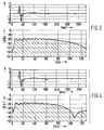
- Figs. 3-5 show the time signature and frequency spectrum (0-128 Hz) for the 1545 cubic inch array at each of the three measured depths 6, 7,5 and 9 metres, respectively.
- the upper horizontal axes represent time (in milliseconds) whereas the lower horizontal axes represent frequency (in Hz).
- the upper vertical axes represent amplitude, whereas the lower vertical axes represent power (in dB).
- the 1545 cubic inch array is robust enough to be used at any depth between 6 and 9 metres while still maintaining its desirable spectral characteristics.
- Fig. 6 compares the spectra of the 1512 cubic inch array at 6 metres (solid line) with the spectra of the 1545 cubic inch array at 9 metres (dashed line).
- the 1545 cubic inch array has more amplitude at all frequencies between 7 and 58 Hz. Also, because the guns would be towed 50% further from the floats from which they are suspended than the 1512 cubic inch subarray, the pressure pulses experienced by the floats from the expanding bubbles would be significantly reduced with the new array at the deeper depth.
- An array resulting from the method of the present invention was compared to an array resulting from Nooteboom's method and the method of US 4,382,486.
- the total volume and number of guns of all three arrays were kept constant at 1517 cubic inches and 8 guns.
- the output of each array was simulated as noted hereinbefore.
- the volumes (in cubic inches) of the air guns for the three arrays are listed below: US 4,382,486 ARRAY NOOTEBOOM'S ARRAY PRESENT INVENTION ARRAY 454 438 498 310 307 300 218 224 206 161 168 152 122 130 119 97 102 96 81 82 79 74 66 67
- the simulation was again performed with the guns in a line ascending from the smallest volume to the largest volume.
- the distance from the smallest to largest gun in each array was 19 metres.
- the distances between adjacent guns was selected to achieve a constant spacing factor for each array.
- the spacing factors were 2.15 for the array determined by the methods of the present invention, 2.12 for the array determined by the method of Nooteboom and 2.13 for the array determined by the method of US 4,382,486.
- the output of the array was simulated at 33 metres below the center of the array. All three arrays were simulated at a depth of 6 metres and an operating pressure of 2000 psia (137 bar).
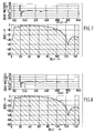
- Figs. 7-9 show the time signature and frequency spectrum (0-128 Hz) for these three arrays.
- the upper horizontal axis of each figure represent time (in milliseconds) wheras the lower horizontal axes represent frequency (in Hz).
- the upper vertical axes of each figure represent amplitude (in bar-metres) whereas the lower vertical axes represent power (in dB).
- Fig. 7 results from the array of the present invention.
- Fig. 8 results from the Nooteboom array and Fig. 9 results from the array of US 4,382,486.
- Fig. 10 shows the spectra of all three arrays in a log frequency plot (3-128 Hz).
- the horizontal axis represents frequency (in Hz) whereas the vertical axis represents power (in dB).
- the solid line represents the array of the present invention, while the short dashed line represents the array of Nooteboom's method and the long dashed line represents the array of the method of US 4,382,486. From Fig. 10, it may be seen that the array of the present invention provides a flatter composite spectrum.
- the frequencies of the air guns that make up the array are determined in accordance with the methods of the present invention, it is then possible to determine the appropriate operating parameters for the air guns.
- the operating pressure and depth are known so that only air gun volumes may be manipulated to provide the determined frequency.
- a marine seismic array that is made up of unique elements, with each element of the array having a dominant unique frequency, and with the variation of amplitude with frequency for such an element known (either experimentally or theoretically).
- Water guns as an example, may be employed in seismic arrays the size of whose elements are determined by the method of the present invention.
Landscapes
- Engineering & Computer Science (AREA)
- Remote Sensing (AREA)
- Physics & Mathematics (AREA)
- Life Sciences & Earth Sciences (AREA)
- Acoustics & Sound (AREA)
- Environmental & Geological Engineering (AREA)
- Geology (AREA)
- General Life Sciences & Earth Sciences (AREA)
- General Physics & Mathematics (AREA)
- Geophysics (AREA)
- Geophysics And Detection Of Objects (AREA)
- Medicines Containing Plant Substances (AREA)
Claims (4)
- Procédé pour déterminer les fréquences d'une source sismique d'un réseau de sources sismiques marines qui utilisent un choc par explosion ou impulsion pour engendrer une énergie rayonnée et sont tractées derrière un navire d'exploration sismique en étant associées à une flûte munie de détecteurs sismiques, dans lequel les sources sismiques de volume plus petit remplissent et adoucissent de manière adéquate les creux des sources sismiques de volume plus important, plus puissantes, pour fournir un spectre composite plus plat pour le réseau dans son entier, caractérisé en ce qu'il comporte les étapes consistant à :- choisir un point de départ situé dans la plage de 5 à 15 Hz pour la fréquence F₁ minimale ou la plus basse d'un spectre de fréquences de réseau voulu, correspondant à la dimension de la source sismique maximale ou la plus grande,- choisir le nombre N de sources sismiques dans le réseau,- déterminer les fréquences des sources sismiques restantes à partir du jeu d'équations suivant :


pour i = 1 à N - 1, soumis à la contrainte - résoudre de manière itérative ledit jeu d'équations à partir de la fréquence de fin basse, donc,- dériver un jeu de fréquences Fi (i = 1 à N) dans lequel Fi + 1 > Fi et un jeu de différences de fréquences Δi (i = 1 à N),- ajuster la valeur de Δ₁ en fonction de la quantité de différence entre deux fois la fréquence de la source sismique de volume le plus grand et FN + ΔN, et- répéter ensuite le traitement de résolution itérative pour calculer un jeu de fréquences Fi et de différences de fréquence Δi jusqu'à ce que la première octave soit correctement remplie (c'est à dire à l'intérieur d'une limite présélectionnée voulue).
 - Procédé selon la revendication 1, caractérisé en ce que lesdites sources sismiques sont des canons à air.
- Procédé selon la revendication 1, caractérisé en ce que lesdites sources sismiques sont des canons à eau.
- Procédé selon l'une quelconque des revendications 1 à 3, caractérisé en ce que le nombre de sources sismiques est huit.
Applications Claiming Priority (2)
| Application Number | Priority Date | Filing Date | Title |
|---|---|---|---|
| US13115487A | 1987-12-10 | 1987-12-10 | |
| US131154 | 1987-12-10 |
Publications (3)
| Publication Number | Publication Date |
|---|---|
| EP0320073A2 EP0320073A2 (fr) | 1989-06-14 |
| EP0320073A3 EP0320073A3 (fr) | 1991-07-03 |
| EP0320073B1 true EP0320073B1 (fr) | 1994-05-18 |
Family
ID=22448138
Family Applications (1)
| Application Number | Title | Priority Date | Filing Date |
|---|---|---|---|
| EP88202806A Expired - Lifetime EP0320073B1 (fr) | 1987-12-10 | 1988-12-07 | Faisceau de canons à air |
Country Status (7)
| Country | Link |
|---|---|
| EP (1) | EP0320073B1 (fr) |
| JP (1) | JPH01196590A (fr) |
| AU (1) | AU603939B2 (fr) |
| CA (1) | CA1314971C (fr) |
| DE (1) | DE3889641T2 (fr) |
| MY (1) | MY103648A (fr) |
| NO (1) | NO885469L (fr) |
Cited By (1)
| Publication number | Priority date | Publication date | Assignee | Title |
|---|---|---|---|---|
| CN1954239B (zh) * | 2004-05-04 | 2010-12-08 | 维斯特恩格科地震控股有限公司 | 增强盐下成像的低频采集和处理 |
Families Citing this family (5)
| Publication number | Priority date | Publication date | Assignee | Title |
|---|---|---|---|---|
| US5281773A (en) * | 1991-08-28 | 1994-01-25 | Exxon Production Research Company | Controlled phase marine source subarray |
| AU2395097A (en) * | 1997-04-21 | 1998-11-13 | Mo Safar | A new efficient method of operating air-gun arrays |
| GB2329963B (en) * | 1997-04-21 | 2001-05-30 | Mo Safar | A new efficient method of operating air-gun arrays |
| US9360578B2 (en) | 2010-08-24 | 2016-06-07 | Schlumberger Technology Corporation | Systems and methods for optimizing low frequency output from airgun source arrays |
| EP2710410A4 (fr) * | 2011-05-20 | 2015-10-28 | Schlumberger Technology Bv | Systèmes et procédés d'optimisation de la puissance de sortie à basse fréquence émanant de réseaux de sources de type canon à air |
Family Cites Families (6)
| Publication number | Priority date | Publication date | Assignee | Title |
|---|---|---|---|---|
| US438246A (en) * | 1890-10-14 | Hugh silver | ||
| US3893539A (en) * | 1972-10-21 | 1975-07-08 | Petty Ray Geophysical Inc | Multiple air gun array of varied sizes with individual secondary oscillation suppression |
| GB2062227B (en) * | 1979-10-25 | 1983-09-21 | Horizon Exploration Ltd | Underwater seismic testing |
| US4382486A (en) * | 1981-02-05 | 1983-05-10 | Mobil Oil Corporation | Tuned air gun array |
| FR2535469B1 (fr) * | 1982-10-28 | 1985-06-21 | Geophysique Cie Gle | Procede pour creer sous la surface d'une nappe d'eau une onde de choc a partir d'une pluralite de sources sismiques a implosion, et appareillage pour sa mise en oeuvre |
| FR2566135B1 (fr) * | 1984-06-18 | 1987-05-15 | Inst Francais Du Petrole | Procede pour optimiser le spectre de frequence des impulsions emises par des sources sismiques a implosion |
-
1988
- 1988-11-28 CA CA000584298A patent/CA1314971C/fr not_active Expired - Fee Related
- 1988-12-07 EP EP88202806A patent/EP0320073B1/fr not_active Expired - Lifetime
- 1988-12-07 DE DE3889641T patent/DE3889641T2/de not_active Expired - Fee Related
- 1988-12-08 NO NO88885469A patent/NO885469L/no unknown
- 1988-12-08 MY MYPI88001415A patent/MY103648A/en unknown
- 1988-12-08 JP JP63310974A patent/JPH01196590A/ja active Pending
- 1988-12-08 AU AU26717/88A patent/AU603939B2/en not_active Ceased
Cited By (1)
| Publication number | Priority date | Publication date | Assignee | Title |
|---|---|---|---|---|
| CN1954239B (zh) * | 2004-05-04 | 2010-12-08 | 维斯特恩格科地震控股有限公司 | 增强盐下成像的低频采集和处理 |
Also Published As
| Publication number | Publication date |
|---|---|
| NO885469D0 (no) | 1988-12-08 |
| CA1314971C (fr) | 1993-03-23 |
| DE3889641D1 (de) | 1994-06-23 |
| AU603939B2 (en) | 1990-11-29 |
| AU2671788A (en) | 1989-06-15 |
| EP0320073A2 (fr) | 1989-06-14 |
| EP0320073A3 (fr) | 1991-07-03 |
| MY103648A (en) | 1993-08-28 |
| JPH01196590A (ja) | 1989-08-08 |
| NO885469L (no) | 1989-06-12 |
| DE3889641T2 (de) | 1994-09-01 |
Similar Documents
| Publication | Publication Date | Title |
|---|---|---|
| EP1214610B1 (fr) | Procede de releve sismique, dispositif de vibreurs marins, et procede de calcul des profondeurs des sources sismiques | |
| Rajan et al. | Perturbative inversion methods for obtaining bottom geoacoustic parameters in shallow water | |
| Harrison et al. | Geoacoustic inversion of ambient noise: A simple method | |
| Stoll | Velocity dispersion in water-saturated granular sediment | |
| EP0115359B1 (fr) | Procédé et dispositif pour améliorer les signaux dans la prospection sismique sous-marine | |
| EP0968443B1 (fr) | Systeme de prospection geophysique utilisant un vibrateur de prospection sismique assurant un balayage composite | |
| EP0515188B1 (fr) | Procédé de la suppression de données de multiples | |
| Chapman et al. | Matched-field inversion for geoacoustic model parameters in shallow water | |
| GB2319611A (en) | Marine seismic surveying | |
| EP0320073B1 (fr) | Faisceau de canons à air | |
| Stoll et al. | Measuring lateral variability of sediment geoacoustic properties | |
| EP0288154A2 (fr) | Méthode d'estimation des données d'ondes de cisaillement réfléchies obtenues à partir des données d'ondes de compression réfléchies | |
| CA1157138A (fr) | Methode et dispositif de sismographie | |
| Shen et al. | Modeling of multi-depth slanted airgun source for deghosting | |
| EP0689064B1 (fr) | Procédés pour diminuer adaptivement du bruit transistoire dans les signaux sismiques des capteurs localisés dans le même point | |
| US5241513A (en) | Correlation system for nonlinear vibratory signals | |
| Tollefsen | Thin-sediment shear-induced effects on low-frequency broadband acoustic propagation in a shallow continental sea | |
| Ohkawa et al. | Acoustic backscattering from a sandy seabed | |
| Johnston et al. | Marine seismic energy sources: acoustic performance comparison | |
| Grinyuk et al. | Experimental study of mode selection in shallow-water sea | |
| Zaslavskiĭ et al. | Vertical seismic profiling on the sea shelf | |
| Harrison | The influence of noise and coherence fluctuations on a new geo-acoustic inversion technique | |
| Focke et al. | Problem of the caustics in range‐averaged ocean sound channels | |
| Lunnon et al. | An Evaluation of Peak and Bubble Tuning in Sub-Basalt Imaging–Modelling and Results | |
| Schmidt et al. | Boundary element simulation of long‐range facet reverberation |
Legal Events
| Date | Code | Title | Description |
|---|---|---|---|
| PUAI | Public reference made under article 153(3) epc to a published international application that has entered the european phase |
Free format text: ORIGINAL CODE: 0009012 |
|
| AK | Designated contracting states |
Kind code of ref document: A2 Designated state(s): DE FR GB NL |
|
| PUAL | Search report despatched |
Free format text: ORIGINAL CODE: 0009013 |
|
| AK | Designated contracting states |
Kind code of ref document: A3 Designated state(s): DE FR GB NL |
|
| 17P | Request for examination filed |
Effective date: 19911206 |
|
| 17Q | First examination report despatched |
Effective date: 19921110 |
|
| GRAA | (expected) grant |
Free format text: ORIGINAL CODE: 0009210 |
|
| AK | Designated contracting states |
Kind code of ref document: B1 Designated state(s): DE FR GB NL |
|
| REF | Corresponds to: |
Ref document number: 3889641 Country of ref document: DE Date of ref document: 19940623 |
|
| ET | Fr: translation filed | ||
| PGFP | Annual fee paid to national office [announced via postgrant information from national office to epo] |
Ref country code: GB Payment date: 19941108 Year of fee payment: 7 |
|
| PGFP | Annual fee paid to national office [announced via postgrant information from national office to epo] |
Ref country code: FR Payment date: 19941128 Year of fee payment: 7 |
|
| PLBE | No opposition filed within time limit |
Free format text: ORIGINAL CODE: 0009261 |
|
| STAA | Information on the status of an ep patent application or granted ep patent |
Free format text: STATUS: NO OPPOSITION FILED WITHIN TIME LIMIT |
|
| 26N | No opposition filed | ||
| PG25 | Lapsed in a contracting state [announced via postgrant information from national office to epo] |
Ref country code: NL Effective date: 19950701 |
|
| NLV4 | Nl: lapsed or anulled due to non-payment of the annual fee |
Effective date: 19950701 |
|
| PG25 | Lapsed in a contracting state [announced via postgrant information from national office to epo] |
Ref country code: DE Effective date: 19950901 |
|
| PG25 | Lapsed in a contracting state [announced via postgrant information from national office to epo] |
Ref country code: GB Effective date: 19951207 |
|
| GBPC | Gb: european patent ceased through non-payment of renewal fee |
Effective date: 19951207 |
|
| PG25 | Lapsed in a contracting state [announced via postgrant information from national office to epo] |
Ref country code: FR Effective date: 19960830 |
|
| REG | Reference to a national code |
Ref country code: FR Ref legal event code: ST |
|
| REG | Reference to a national code |
Ref country code: FR Ref legal event code: TP |