EP0320157B1 - Appareil de contrôle pour literie chauffée électriquement - Google Patents
Appareil de contrôle pour literie chauffée électriquement Download PDFInfo
- Publication number
- EP0320157B1 EP0320157B1 EP88311249A EP88311249A EP0320157B1 EP 0320157 B1 EP0320157 B1 EP 0320157B1 EP 88311249 A EP88311249 A EP 88311249A EP 88311249 A EP88311249 A EP 88311249A EP 0320157 B1 EP0320157 B1 EP 0320157B1
- Authority
- EP
- European Patent Office
- Prior art keywords
- heating
- timer circuit
- control means
- hour
- control
- Prior art date
- Legal status (The legal status is an assumption and is not a legal conclusion. Google has not performed a legal analysis and makes no representation as to the accuracy of the status listed.)
- Expired - Lifetime
Links
Images

Classifications
-
- H—ELECTRICITY
- H05—ELECTRIC TECHNIQUES NOT OTHERWISE PROVIDED FOR
- H05B—ELECTRIC HEATING; ELECTRIC LIGHT SOURCES NOT OTHERWISE PROVIDED FOR; CIRCUIT ARRANGEMENTS FOR ELECTRIC LIGHT SOURCES, IN GENERAL
- H05B1/00—Details of electric heating devices
- H05B1/02—Automatic switching arrangements specially adapted to apparatus ; Control of heating devices
- H05B1/0202—Switches
- H05B1/0225—Switches actuated by timers
-
- H—ELECTRICITY
- H05—ELECTRIC TECHNIQUES NOT OTHERWISE PROVIDED FOR
- H05B—ELECTRIC HEATING; ELECTRIC LIGHT SOURCES NOT OTHERWISE PROVIDED FOR; CIRCUIT ARRANGEMENTS FOR ELECTRIC LIGHT SOURCES, IN GENERAL
- H05B3/00—Ohmic-resistance heating
- H05B3/20—Heating elements having extended surface area substantially in a two-dimensional [2D] plane, e.g. plate-heater
- H05B3/34—Heating elements having extended surface area substantially in a two-dimensional [2D] plane, e.g. plate-heater flexible, e.g. heating nets or webs
- H05B3/342—Heating elements having extended surface area substantially in a two-dimensional [2D] plane, e.g. plate-heater flexible, e.g. heating nets or webs heaters used in textiles
-
- H—ELECTRICITY
- H05—ELECTRIC TECHNIQUES NOT OTHERWISE PROVIDED FOR
- H05B—ELECTRIC HEATING; ELECTRIC LIGHT SOURCES NOT OTHERWISE PROVIDED FOR; CIRCUIT ARRANGEMENTS FOR ELECTRIC LIGHT SOURCES, IN GENERAL
- H05B2203/00—Aspects relating to Ohmic resistive heating covered by group H05B3/00
- H05B2203/014—Heaters using resistive wires or cables not provided for in H05B3/54
Definitions
- This invention relates to control apparatus for heating arrangements.
- US Patent US-A-4 176 785 discloses a control apparatus for a heating arrangement in the form of a gas or oil fired furnace, the control apparatus including a 24 hour timer circuit and heating control means responsive to the timer circuit to control operation of the heating arrangement.
- UK Patent Application Publication No GB-A-2 157 514 discloses a control apparatus for an electric blanket including means operative to interrupt flow of heating current through a heating element of the blanket in the event of an excessive temperature being attained.
- control apparatus for a heating arrangement, the control apparatus including a 24 hour timer circuit and heating control means responsive to the timer circuit to control operation of the heating arrangement, and the control apparatus being characterised in that:
- Such an apparatus is very simple to use.
- the user need only connect the control apparatus to an electrical supply and then perform the manual setting operation at an appropriate time of day. Thereafter, provided the apparatus is left connected to the supply, heating of the bed will be enabled each day at the same time ("on time") as that determined by the time at which the setting operation was performed and will be disabled each day at the same time ("off time”), namely at the end of the predetermined part of the 24 hour cycle. Setting of the on time (and consequential automatic setting of the off time), is thus very simple.
- Another advantage of the present apparatus is that, in the event of temporary supply failure, the 24 hour cycle will not recommence until the manual setting operation has been performed again, thereby preventing the on and off times being offset by an amount equal to the duration of the failure, which would be the case in the event of using a plug-in timer.
- This feature not only avoids the inconvenience of operation at the wrong time, but is an advantage from the point of view of fire safety in that it minimises the chance of the arrangement being heated at a time of day when the bedroom is not occupied.
- the timer circuit control means includes delay means operative to prevent the 24 hour timer reverting to a stand-by state unless the energisation signal indicates that the control apparatus has been de-energised for more than a predetermined interval of, for example, 30 seconds.
- the apparatus comprises a switch for performing the manual setting operation, whereby the operation can be performed by a single switch actuation.
- the timer circuit control means preferably comprises delay means operative to prevent the timer circuit being set unless the switch has been actuated for at least a predetermined duration (e.g. 2.5 seconds) in order to prevent spurious or accidental operation.
- the apparatus may include indicator means for indicating whether (i) the apparatus is energised and awaiting the manual setting operation or (ii) the manual setting operation has been performed whilst the apparatus is energised whereby the timer circuit has been set. In the case of (ii), the indication may distinguish between the heating control means being enabled and disabled.
- the timer circuit control means is responsive to an over-ride command, if received during said predetermined part of the 24 hour cycle, to cause the timer circuit to disable energisation of the heating control means (whereby the heating is turned off, before the end of said predetermined part of the 24 hour cycle, without disturbing the cycle) and, if received outside of the predetermined part of the 24 hour cycle, to cause the timer circuit to enable energisation of the heating control means (whereby the heating is turned on, prior to the start of the said predetermined part of the 24 hour cycle, without disturbing the cycle).
- the over-ride command operation can be performed by a single switch actuation operation, which may comprise actuation of the above-mentioned switch preferably used to perform the manual setting operation.
- the control apparatus preferably includes heating level selection means for controlling the heating control means in such a manner as to enable heating at a manually selected one of a plurality of heating levels.
- the 24 hour timer circuit may be operative to over-ride the selected heating level setting, if necessary, during an initial portion (e.g. 80 minutes) of the predetermined part (e.g. 12 hours) of the 24 hour cycle to provide heating at a level (e.g. the higher or highest level) which will provide a high level of heat. This enables a fast warm-up of the bed, after which heating reverts to the selected level.
- the apparatus may include overheat protection means operating independently of the heating control means to interrupt flow of heating current through the heating element in the event of an excessive temperature (for instance a localised excessive temperature caused by rucking of the blanket or other arrangement) being attained. This feature minimises, of course, the risk of fire.
- overheat protection means operating independently of the heating control means to interrupt flow of heating current through the heating element in the event of an excessive temperature (for instance a localised excessive temperature caused by rucking of the blanket or other arrangement) being attained.
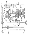
- FIG. 1 is a block schematic circuit diagram of a first control apparatus embodying the invention for an electric bed heating arrangement, for instance an electric blanket or electric duvet.
- the apparatus includes a pair of input terminals 10, 12 for connection to the live (L) and neutral (N) conductors of an a c power supply (not shown).
- the input terminals 10, 12 are connected via a two-pole isolation (on/off) switch 14 to the series combination of a thermal fuse 16, a heating conductor 18, a protective diode 20 and a thyristor 22.
- the heating conductor 18 forms part of a heating cable 24 which is tortuously disposed in the electric blanket or duvet.
- the cable 24 is of a dual coaxial type known in the art and comprises an inner core (not shown) on which the heating conductor 18 is wound.
- a layer 26 of polyethylene surrounds the heating conductor 18 and a sensor conductor 28 is wound around the polyethylene layer 26.
- the ends of the sensor conductor 28 are connected together and are connected via a resistor 30 and the on/off switch 14 to the input terminal 12.
- the resistor 30 is thermally coupled to the thermal fuse 16.
- the thermal fuse 16 is a non-resettable thermal link and comprises a current carrying device (generally incorporating a low melting point alloy) responsive to the application of external heat to non-resettably stop the passage of current therethrough.
- the apparatus illustrated in Figure 1 further comprises a d c power supply 32 which derives from the a c supply, when the switch 14 is closed, d c power for application to various of the circuit components illustrated in Figure 1. For the sake of clarity, the connections to the various circuit components are not shown.
- the apparatus illustrated in Figure 1 also comprises a latch circuit 34, a 24 hour timer circuit 36 (which may comprise an integrated circuit similar to those conventionally used in electrical watches and which includes an output stage 38), an indicator control circuit 40, a heating level selection circuit 42 and a pulse generator 44 for supplying pulses for firing the thyristor 22.
- a "power" lamp 46 and a “standby” lamp 48 are each connected to the indicator control circuit 40.
- a reset/over-ride switch (not shown in Figure 1) is connected to an input of the latch circuit 34, and a heating level switch (not shown in Figure 1) is connected to an input of the heating level selection circuit 42.
- the control apparatus shown in Figure 1 operates in the following manner.
- a c power is supplied to the d c power supply 32 whereby the various circuits shown in Figure 1 are energised.
- a signal indicating the presence of d c power is applied from the d c power supply 32, to the latch circuit 34, via a line 50.
- the level on a line 52 that connects an output of the latch circuit 34 to a "SET" input 53 of the 24 hour timer circuit 36 and to an input of the indicator control circuit 40 is such as not to set the timer circuit 36 and such as to cause the indicator control circuit 40 to cause both the lamps 46 and 48 to flash.
- the fact that the timer circuit 36 is not set causes the output stage 38 thereof to produce on a line 54, which is connected to the indicator control circuit 40 and also to the pulse generator 44, a signal which is of such a level as to disable operation of the pulse generator 44. Consequently, pulses are not supplied from the pulse generator 44 to the thyristor 22 whereby heating of the blanket or duvet cannot take place. That is to say, in this state, heating is disabled, a 24 hour cycle of operation of the timer circuit 36 has not commenced, and the lights 46, 48 are caused to flash to indicate that the apparatus is in this state.
- the user then operates the reset/over-ride switch to apply an input to the latch circuit 34.
- the latch circuit 34 includes delay means (not shown), for example a resistive-capacitive network, responsive to the reset/over-ride switch being continually operated for at least 2.5 seconds to change the level on the line 52.
- the change in level on the line 52 has two effects. Firstly, it causes the 24 hour timer circuit 36, via the "SET" input 53 thereof, to commence its 24 hour cycle. Secondly, it is operative on the indicator control circuit 46 to stop flashing of the lamps 46, 48, thereby indicating that the 24 hour cycle has commenced.
- the power part For a predetermined part of the 24 hour cycle, which part (hereinafter “the power part") has a duration of 12 hours and commences as of the start of the 24 hour cycle, firing of the thyristor 22 is enabled. This is accomplished by the level on the line 54 changing so as to enable operation of the pulse generator 44. The change in level on the line 54 also is applied to the indicator control circuit 40. During the power part of the 24 hour cycle, namely the part during which heating can take place, the indicator control circuit 40 is responsive to the level of the signal on the line 54 to light the "power" lamp 46.
- the level of the line 54 is such as to disable the pulse generator 44 and to cause the indicator control circuit 40 to light the "standby" lamp 48, thereby indicating that the apparatus is in the standby part of the cycle, namely the part during which heating cannot take place.
- the heating level switch is connected to the heating level selection circuit 42, such connection being affected by way of a line 56 (which may in fact comprise a plurality of lines each associated with a respective heating level).
- the heating level selection circuit 42 is operative on the pulse generator 44, via a line 58, to control the operation of the generator 44 in such a manner as to achieve heating to a level selected by the circuit 42.
- the apparatus may, for instance, have two heating level settings. In a first of the heating level settings, the pulse generator 44 produces pulses which trigger the thyristor 22 to conduct during substantially all of every alternate positive half-cycle of the a c supply, whereby a maximum degree of heating is achieved.
- the heating level selection circuit 42 is operative to enable the pulse generator 44 to trigger the thyristor 22 into conduction only during alternate positive half-cycles.
- the circuit 42 may comprise a delay means or a timing/gating circuit.
- Other heating levels may be selected by varying the number of half-cycles of the a c supply during which the thyristor 22 is triggered into conduction. For example, four heating levels may be selected, the heating levels corresponding to 100%, 75%, 50% and 25% power and corresponding to the thyristor 22 being energised during all positive half-cycles, three out of four positive half-cycles, alternate positive half-cycles and every fourth positive half-cycle, respectively.
- the output stage 38 of the 24 hour timer circuit 36 is connected to the heating level selection circuit 42 by a line 60.
- a signal on the line 60 is of such a level as to override the operation of the heating level selection circuit 42 in such a manner as to cause it, via the line 58, to make the pulse generator operate as if the higher or highest heating level had been selected. This enables rapid warming up of the bed.
- the level on the line 60 changes and the heating level selection circuit 42 thereafter causes the pulse generator 44 to operate in accordance with the selected heating level.
- the blanket or duvet will be switched on at the same time each day (namely the time at which the 24 hour timer circuit was set) and pre-heated at a high setting for 80 minutes, after which heating will be continued (at whichever heating level is selected or set) until 12 hours after it was switched on. After this, the blanket or duvet will be switched off for 12 hours, and the whole 24 hour cycle thereafter is repeated indefinitely.
- the latch circuit 34 monitors, during operation, whether the signal on the line 50, which indicates energisation of the apparatus, is maintained. This signal is monitored via a delay means (not shown), which may be a resistive-capacitive circuit and may provide a delay of, for example, 30 seconds. If the signal on the line 50 disappears for more than 30 seconds, indicating a power supply failure having a duration of more than 30 seconds, the latch circuit 34 changes the level on the line 52. The apparatus then reverts to its original state.
- the 24 hour timer circuit 36 is no longer set, whereby the pulse generator 44 is disabled to prevent heating and heating cannot be enabled again until the reset/over-ride switch is operated again, for at least 2.5 seconds; and the lights 46, 48 are caused to flash to indicate that the apparatus is in this state.
- the latch circuit 34 supplies an over-ride signal to the output stage 38 of the timer 36 via a line 62.
- the over-ride signal is received during the power part of the 24 hour cycle, namely that part during which the operation of the pulse generator 44 is enabled, the pulse generator is disabled via the line 54 whereby the apparatus effectively "jumps" to the next part (standby part) of the 24 hour cycle.
- the pulse generator 44 is disabled
- the pulse generator is enabled via the line 54 whereby the apparatus effectively "jumps" to the power part of the next 24 hour cycle.
- the user can over-ride the set on and off times of the timer circuit 36, without disturbing their settings, for example if he retires and/or rises at a different time than usual.
- overheating of the cable 24 takes place.
- Such overheating can, for example, arise as a result of arcing across a break in the heating conductor 18 or due to intense localised overheating due to rucking of the blanket or duvet.
- the polyethylene layer 26 melts at the location of the overheat, enabling the heating conductor 18 and the sensor conductor 28 to come into contact with one another.
- the a c supply voltage is applied across the series combination of part of the conductor 18 and the resistor 30.
- the current flowing through the resistor 30 rises from a negligibly small value to a substantial value.
- the resistor 30 is therefore heated and heats the thermal fuse 16.
- the thermal fuse 16 then melts to non-resettably (permanently) interrupt the flow of current to the heating conductor. It will be noted that the operation of this overheat protection feature is independent of the operation of controlling heating provided by the heating level selection circuit 42, the pulse generator 44 and so forth.
- the voltage developed in the above event across the resistor 30 may, as shown, be fed back to the pulse generator 44 to inhibit the operation of the pulse generator and thus de-energise the heating conductor 18 immediately the voltage is developed across the resistor.
- current flow through the heating conductor 18, in the event of arcing of the heating conductor or intense localised overheating due to a ruck, is inhibited while the resistor 30 heats up sufficiently to activate the thermal fuse 16 to interrupt the flow of current permanently.
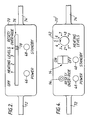
- FIG. 2 An external view of a housing 70 containing the apparatus of Figure 1 is shown in Figure 2.
- the housing 70 incorporates all the components shown in Figure 1 except, of course, the cable 24.
- the housing 70 is fixed in an "in-line" manner in a cord for the blanket or duvet, the cord comprising a first portion 72 which is terminated in a plug (not shown) for connection to an a c supply outlet (socket) and a second portion 74 which contains three wires connecting the apparatus to the two ends of the heating conductor 18 and to one end of the sensor conductor 28.
- the lamps 46 and 48 are, as shown in Figure 2, mounted to the housing 70 so as readily to be visible by the user.
- FIG. 2 shows a slider switch mechanism 76 that enables the on/off switch 14, the reset/over-ride switch and the heating level switch to be combined.
- the switch mechanism 76 comprises a slider 78 movable between six positions, namely an off position, four heating level positions (1, 2, 3 and 4) and a reset/over-ride position.
- the slider 78 is in the off position.
- the on/off switch 14 is closed.
- the lamps 46, 48 begin to flash.
- the user moves the slider 78 from the off position to the reset/over-ride position at that time of day.
- the timer circuit 36 is set. Also, the lamps 46, 48 stop flashing, the lamp 46 is illuminated continuously and the lamp 48 ceases to be illuminated, thereby indicating that the timer has been set and that the first (power) part of the 24 hour cycle (during which heating is enabled) has commenced. The user then moves the slider 78 to the position corresponding to the heating level he wishes to select.
- Figure 3 is a block schematic circuit diagram of a second control apparatus embodying the invention for an electric bed heating arrangement such as an electric blanket or electric duvet.
- the apparatus of Figure 3 is constructed and operates very much in the same manner as that of Figure 1 and will be described only in so far as it differs therefrom.
- Reference numerals used in Figure 3 which are the same as reference numerals used in Figure 1 designate similar items.
- a second dual coaxial cable 80 is tortuously disposed within the electric blanket or duvet, preferably in close proximity to the cable 24, to sense the temperature to which the blanket or duvet is heated.
- the cable 80 comprises two sensor conductors 82, 84 separated by a layer 86 of polyvinyl chloride (PVC) which, in a manner known in the art, has been doped with a material which enhances its conductivity.
- PVC polyvinyl chloride
- the ends of the conductor 82 are connected together and are connected via the thermal fuse 16 and the on/off switch 14 to the input terminal 10.
- the ends of the conductor 84 are connected together and are connected via a resistor 88 and the switch 14 to the input terminal 12.
- the a c supply voltage is applied in use, across the series combination of the impedance of the layer 86 and the resistor 88.
- the junction between the sensor conductor 84 and the resistor 88 is connected by a line 90 to an input of the heating level selection circuit, which is referenced 42′ in Figure 3.
- the heating level selection 42′ generates (for instance by means of a variable potential divider network) a d c voltage which is proportional to the heating level selected by the heating level switch.
- a d c voltage which is proportional to the heating level selected by the heating level switch.
- the signal applied to the line 58 is made such as to enable the pulse generator 44.
- the signal on the line 58 is changed to disable the pulse generator 44. That is to say, in this embodiment, the pulse generator 44 is switched on and off as appropriate, in a manner to maintain the desired bed temperature, the pulse generator 44 being operative to trigger the thyristor 22 into conduction during all positive half-cycles when the pulse generator is enabled.
- the cable 80, resistor 88 and heating level selection circuit 42′ act in a manner analogous to a thermostat to control heating to enable any selected one of a plurality of desired temperatures to be achieved.
- Figure 4 shows a housing 70′ for the apparatus shown in Figure 3.
- the housing 70′ is in many respects similar to the housing 70 of Figure 2 and will only be described in so far as it differs therefrom.
- reference numerals which are the same as reference numerals used in Figure 2 designate similar items.
- the various switches are separate.
- the on/off switch 14 may be a rocker switch
- the heating level switch may be a separate switch operated by a rotary knob 92
- the reset/over-ride switch may be a push button switch 94 which is preferably spring biased so as to be actuated only when held depressed.
- the invention can of course be embodied in other ways than those described above by way of example.
- current flow could be controlled by other devices than a thyristor, for example a triac (in which event a c rather than half-wave rectified a c current would flow through the heating conductor).
- the layer 26 of the cable 24 could be of other materials than polyethylene.
- the material could, for instance, be of PVC (possibly doped with a conductivity-enhancing substance), in which event the resistor 30 might become heated to an extent to activate the thermal fuse, without the conductors 18 and 28 contacting one another, due to a decrease in the impedance of the PVC layer 26 caused by its becoming heated by arcing or by local intense overheating caused by a ruck.
Landscapes
- Engineering & Computer Science (AREA)
- Textile Engineering (AREA)
- Control Of Resistance Heating (AREA)
- Heating, Cooling, Or Curing Plastics Or The Like In General (AREA)
- Tunnel Furnaces (AREA)
Claims (12)
- Dispositif de commande pour un appareil de chauffage (24), le dispositif de commande incluant un circuit temporisateur de 24 heures (36) et un moyen de commande de chauffage (44, 22) sensible au circuit temporisateur pour commander le fonctionnement de l'appareil de chauffage, et le dispositif de commande étant caractérisé en ce que :(i) il est connecté de manière à commander un appareil électrique de chauffage de lit et en ce que le moyen de commande de chauffage (44, 22) sert à commander le débit du courant de chauffage dans un élément électrique chauffant (18) dans l'appareil de chauffage de lit ;(ii) il comprend un moyen de production d'un signal de mise sous tension (32) servant à produire un signal de mise sous tension qui indique si l'appareil de commande est ou non alimenté par une source d'énergie électrique ;(iii) le circuit temporisateur (36) sert, lorsqu'il est activé, à commencer et à répéter indéfiniment un cycle de 24 heures qui est tel qu'il provoque l'activation du moyen de commande de chauffage (44, 22), chaque jour, à un instant déterminé par l'heure de la journée à laquelle il a été réglé, pour permettre au courant de chauffage de s'écouler dans l'élément chauffant (18) pendant seulement une partie prédéterminée du cycle de 24 heures ; et,(iv) il comprend un moyen de commande de circuit de temporisateur (34) qui est :(a) sensible au fait qu'une opération de réglage manuel est effectuée, pour régler le circuit temporisateur (36), tandis que ledit signal de mise sous tension indique que le dispositif de commande est alimenté ; et(b) sensible audit signal de mise sous tension en indiquant ensuite que le dispositif de commande a été coupé pour faire en sorte que le circuit temporisateur (36) revienne à un état d'attente, ce par quoi le moyen de commande de chauffage (44, 22) est désactivé.
- Dispositif selon la revendication 1, dans lequel le moyen de commande de circuit temporisateur (34) comprend un moyen à retard servant à empêcher le circuit temporisateur de 24 heures (36) de revenir à l'état d'attente à moins que le signal de mise sous tension n'indique que le dispositif de commande a été coupé pendant plus longtemps qu'un intervalle de temps prédéterminé.
- Dispositif selon la revendication 1 ou la revendication 2, qui comprend un commutateur (76, 94) pour effectuer l'opération de réglage manuel, ce par quoi l'opération peut être effectuée par une seule manoeuvre de commutateur.
- Dispositif selon la revendication 3, dans lequel le moyen de commande de circuit temporisateur (34) comprend un moyen à retard servant à empêcher le circuit temporisateur (36) d'être réglé à moins que le commutateur (76, 94) n'ait été actionné pendant au moins une durée prédéterminée.
- Dispositif selon l'une quelconque des revendications précédentes, qui comprend un moyen indicateur (40, 46, 48) pour indiquer si (i) le dispositif est sous tension et attend l'opération de réglage manuel, ou si (ii) l'opération de réglage manuel a été effectuée pendant que le dispositif était sous tension ce par quoi le circuit temporisateur (36) a été réglé.
- Dispositif selon la revendication 5, dans lequel, dans le cas (ii), l'indication fait la distinction entre les cas où le moyen de commande de chauffage (44, 22) est activé et désactivé.
- Dispositif selon l'une quelconque des revendications précédentes, dans lequel le moyen de commande de circuit temporisateur (34), est sensible à une instruction prioritaire, si elle est reçue pendant que ladite partie prédéterminée du cycle de 24 heures, pour faire en sorte que le circuit temporisateur (36) coupe l'alimentation du moyen de commande de chauffage (44, 22), ce par quoi le chauffage est coupé, avant la fin de ladite partie prédéterminée du cycle de 24 heures, sans perturber le cycle, et, si elle est reçue à l'extérieur de ladite partie prédéterminée du cycle de 24 heures, pour faire en sorte que le circuit temporisateur (36) active l'alimentation du moyen de commande de chauffage (44, 22), ce par quoi le chauffage est mis en fonction, avant le démarrage de ladite partie prédéterminée du cycle de 24 heures, sans perturber le cycle.
- Dispositif selon la revendication 7, dans lequel la mise en oeuvre de l'instruction prioritaire peut être effectuée par l'opération de manoeuvre d'un seul commutateur.
- Dispositif selon la revendication 7, lorsqu'elle dépend de la revendication 3 ou 4, dans lequel ladite opération de manoeuvre d'un seul commutateur comprend la manoeuvre dudit commutateur (76, 94) utilisé pour effectuer l'opération de réglage manuel.
- Dispositif selon l'une quelconque des revendications précédentes, qui comprend un moyen de sélection de niveau de chauffage (42 ; 42', 80, 88) pour commander le moyen de commande de chauffage (44, 22) d'une manière telle qu'il active le chauffage à l'un choisi manuellement d'une pluralité de niveaux de chauffage.
- Dispositif selon la revendication 10, dans lequel le circuit temporisateur de 24 heures (36) sert à passer outre au réglage de niveau de chauffage choisi, si nécessaire, pendant une partie initiale de ladite partie prédéterminée du cycle de 24 heures pour établir le chauffage à un niveau qui donnera un niveau de chaleur élevé.
- Dispositif selon l'une quelconque des revendications précédentes, qui comprend un moyen de protection contre la surchauffe (26, 28, 30) servant, indépendamment du moyen de commande de chauffage (44, 22), à interrompre l'écoulement du courant de chauffage dans l'élément électrique chauffant (18) dans le cas où une température excessive serait atteinte.
Priority Applications (1)
| Application Number | Priority Date | Filing Date | Title |
|---|---|---|---|
| AT88311249T ATE94714T1 (de) | 1987-12-07 | 1988-11-28 | Kontrollapparat fuer elektrisch geheizte bettanlagen. |
Applications Claiming Priority (2)
| Application Number | Priority Date | Filing Date | Title |
|---|---|---|---|
| GB8728547A GB2213287B (en) | 1987-12-07 | 1987-12-07 | Control apparatus for electric bed heating arrangements |
| GB8728547 | 1987-12-07 |
Publications (2)
| Publication Number | Publication Date |
|---|---|
| EP0320157A1 EP0320157A1 (fr) | 1989-06-14 |
| EP0320157B1 true EP0320157B1 (fr) | 1993-09-15 |
Family
ID=10628103
Family Applications (1)
| Application Number | Title | Priority Date | Filing Date |
|---|---|---|---|
| EP88311249A Expired - Lifetime EP0320157B1 (fr) | 1987-12-07 | 1988-11-28 | Appareil de contrôle pour literie chauffée électriquement |
Country Status (6)
| Country | Link |
|---|---|
| EP (1) | EP0320157B1 (fr) |
| AT (1) | ATE94714T1 (fr) |
| AU (1) | AU2805789A (fr) |
| DE (1) | DE3884160T2 (fr) |
| GB (1) | GB2213287B (fr) |
| WO (1) | WO1989005560A1 (fr) |
Families Citing this family (3)
| Publication number | Priority date | Publication date | Assignee | Title |
|---|---|---|---|---|
| US5238819A (en) * | 1988-12-14 | 1993-08-24 | The Regents Of The University Of California | Diagnostic assay for the detection of preeclampsia |
| DE10324941A1 (de) | 2003-06-03 | 2005-01-05 | Beurer Gmbh & Co | Schmiegsames elektrisches Wärmegerät |
| CN103458538A (zh) * | 2013-09-10 | 2013-12-18 | 王波兰 | 电热毯加热控制系统 |
Family Cites Families (4)
| Publication number | Priority date | Publication date | Assignee | Title |
|---|---|---|---|---|
| US4176785A (en) * | 1978-09-27 | 1979-12-04 | Amf Incorporated | Automatic temperature controller with night setback and operating as a function of outside air |
| GB2157514A (en) * | 1984-04-13 | 1985-10-23 | Northern Blankets Ltd | Electrical heating circuits |
| FR2599923A1 (fr) * | 1986-06-06 | 1987-12-11 | Degois Cie Ets | Dispositif d'alimentation de securite pour tissu chauffant tel que notamment une couverture chauffante |
| GB2198261A (en) * | 1986-11-14 | 1988-06-08 | Scan Martin Burton | Heating vehicle windscreens |
-
1987
- 1987-12-07 GB GB8728547A patent/GB2213287B/en not_active Expired - Fee Related
-
1988
- 1988-11-28 EP EP88311249A patent/EP0320157B1/fr not_active Expired - Lifetime
- 1988-11-28 AU AU28057/89A patent/AU2805789A/en not_active Abandoned
- 1988-11-28 WO PCT/GB1988/001036 patent/WO1989005560A1/fr not_active Ceased
- 1988-11-28 DE DE88311249T patent/DE3884160T2/de not_active Expired - Fee Related
- 1988-11-28 AT AT88311249T patent/ATE94714T1/de not_active IP Right Cessation
Also Published As
| Publication number | Publication date |
|---|---|
| GB2213287B (en) | 1991-09-04 |
| DE3884160T2 (de) | 1994-01-13 |
| WO1989005560A1 (fr) | 1989-06-15 |
| DE3884160D1 (de) | 1993-10-21 |
| ATE94714T1 (de) | 1993-10-15 |
| GB2213287A (en) | 1989-08-09 |
| AU2805789A (en) | 1989-07-05 |
| GB8728547D0 (en) | 1988-01-13 |
| EP0320157A1 (fr) | 1989-06-14 |
Similar Documents
| Publication | Publication Date | Title |
|---|---|---|
| US4673798A (en) | Dual temperature electric curling iron having a safety shut-off circuit | |
| JPS62271386A (ja) | ガラス−セラミツク系調理用レンジ | |
| US4908498A (en) | Control for delivery of power to heating elements | |
| US4788415A (en) | Dual bimetal power control switching arrangement for electronically controlled appliances | |
| JPH03176987A (ja) | 輻射電気ヒータ | |
| US6689989B2 (en) | Heater for electric blanket | |
| US4764663A (en) | Electric radiation heater assemblies | |
| JPS6013276B2 (ja) | 電気毛布安全回路 | |
| EP0320157A1 (fr) | Appareil de contrôle pour literie chauffée électriquement | |
| US4585926A (en) | Temperature control and indicating arrangement | |
| US2695947A (en) | Deep fat frying attachment for electric ranges | |
| US2588926A (en) | Temperature responsive control circuit | |
| US4874929A (en) | Toaster oven/broiler with continuously energized indicator | |
| US4908496A (en) | Radiant electric heater assemblies | |
| GB2109603A (en) | A cooking control and cooking apparatus including such a control | |
| GB1602734A (en) | Electrically-powered heating panels | |
| US3575584A (en) | Control system and unit for a cooking apparatus and the like | |
| KR900011243Y1 (ko) | 전기밥솥 회로 | |
| US3036189A (en) | Electric cooking range | |
| US3463905A (en) | Combination infinite heat switch and solid-state temperature control | |
| KR860000179Y1 (ko) | 110v/220v 겸용 밥솥의 회로 | |
| JPH04227215A (ja) | 電気ホットプレート用のホットプレート制御装置、そのホットプレート制御装置用の出力制御装置およびホットプレート | |
| GB2332287A (en) | Controlling electrically-powered heating panels | |
| KR920007092Y1 (ko) | 타이머를 이용한 전기보온밥솥의 전원제어 및 동작인지회로 | |
| GB2210215A (en) | Off period-timer |
Legal Events
| Date | Code | Title | Description |
|---|---|---|---|
| PUAI | Public reference made under article 153(3) epc to a published international application that has entered the european phase |
Free format text: ORIGINAL CODE: 0009012 |
|
| AK | Designated contracting states |
Kind code of ref document: A1 Designated state(s): AT BE DE ES FR IT NL SE |
|
| 17P | Request for examination filed |
Effective date: 19891123 |
|
| 17Q | First examination report despatched |
Effective date: 19911205 |
|
| RAP1 | Party data changed (applicant data changed or rights of an application transferred) |
Owner name: DREAMLAND ELECTRICAL APPLIANCES LIMITED |
|
| GRAA | (expected) grant |
Free format text: ORIGINAL CODE: 0009210 |
|
| ITF | It: translation for a ep patent filed | ||
| AK | Designated contracting states |
Kind code of ref document: B1 Designated state(s): AT BE DE ES FR IT NL SE |
|
| PG25 | Lapsed in a contracting state [announced via postgrant information from national office to epo] |
Ref country code: SE Effective date: 19930915 Ref country code: NL Effective date: 19930915 Ref country code: FR Effective date: 19930915 Ref country code: ES Free format text: THE PATENT HAS BEEN ANNULLED BY A DECISION OF A NATIONAL AUTHORITY Effective date: 19930915 Ref country code: BE Effective date: 19930915 Ref country code: AT Effective date: 19930915 |
|
| REF | Corresponds to: |
Ref document number: 94714 Country of ref document: AT Date of ref document: 19931015 Kind code of ref document: T |
|
| REF | Corresponds to: |
Ref document number: 3884160 Country of ref document: DE Date of ref document: 19931021 |
|
| PGFP | Annual fee paid to national office [announced via postgrant information from national office to epo] |
Ref country code: DE Payment date: 19940125 Year of fee payment: 6 |
|
| EN | Fr: translation not filed | ||
| NLV1 | Nl: lapsed or annulled due to failure to fulfill the requirements of art. 29p and 29m of the patents act | ||
| PLBE | No opposition filed within time limit |
Free format text: ORIGINAL CODE: 0009261 |
|
| STAA | Information on the status of an ep patent application or granted ep patent |
Free format text: STATUS: NO OPPOSITION FILED WITHIN TIME LIMIT |
|
| 26N | No opposition filed | ||
| PG25 | Lapsed in a contracting state [announced via postgrant information from national office to epo] |
Ref country code: DE Effective date: 19950801 |
|
| PG25 | Lapsed in a contracting state [announced via postgrant information from national office to epo] |
Ref country code: IT Free format text: LAPSE BECAUSE OF NON-PAYMENT OF DUE FEES;WARNING: LAPSES OF ITALIAN PATENTS WITH EFFECTIVE DATE BEFORE 2007 MAY HAVE OCCURRED AT ANY TIME BEFORE 2007. THE CORRECT EFFECTIVE DATE MAY BE DIFFERENT FROM THE ONE RECORDED. Effective date: 20051128 |