EP0320173A2 - Electrode pour diagnostic - Google Patents
Electrode pour diagnostic Download PDFInfo
- Publication number
- EP0320173A2 EP0320173A2 EP88311401A EP88311401A EP0320173A2 EP 0320173 A2 EP0320173 A2 EP 0320173A2 EP 88311401 A EP88311401 A EP 88311401A EP 88311401 A EP88311401 A EP 88311401A EP 0320173 A2 EP0320173 A2 EP 0320173A2
- Authority
- EP
- European Patent Office
- Prior art keywords
- electrode
- electrodes
- release web
- backing layer
- tab
- Prior art date
- Legal status (The legal status is an assumption and is not a legal conclusion. Google has not performed a legal analysis and makes no representation as to the accuracy of the status listed.)
- Withdrawn
Links
Images


Classifications
-
- A—HUMAN NECESSITIES
- A61—MEDICAL OR VETERINARY SCIENCE; HYGIENE
- A61B—DIAGNOSIS; SURGERY; IDENTIFICATION
- A61B5/00—Measuring for diagnostic purposes; Identification of persons
- A61B5/24—Detecting, measuring or recording bioelectric or biomagnetic signals of the body or parts thereof
- A61B5/25—Bioelectric electrodes therefor
- A61B5/251—Means for maintaining electrode contact with the body
- A61B5/257—Means for maintaining electrode contact with the body using adhesive means, e.g. adhesive pads or tapes
- A61B5/259—Means for maintaining electrode contact with the body using adhesive means, e.g. adhesive pads or tapes using conductive adhesive means, e.g. gels
Definitions
- the present invention pertains to diagnostic electrodes, for example electrodes which may be used in electrocardiogram examinations. It also relates to the dispensing of such electrodes and to a method of affixing them.
- a diagnostic electrode In electrocardiogram examinations, a diagnostic electrode is electrically connected to the diagnostic equipment and affixed to the patient's body. It is important not only properly to position the electrode on the patient but also to do so without excessive handling. Any additional handling of the electrode increases the tendency that the integrity of the electrode may be disturbed, which would in turn foul the results of the test.
- Diagnostic electrodes in contrast to more expensive monitoring electrodes which include a metal snap mounted to an adhesive coated foam, fabric or plastic web wherein an adhesive coated body adhering surface surrounds the conductive gel coated snap, typically comprise a thin, vinyl or paper backing layer, a tin foil layer and a sticky, conductive gel.
- the tin foil layer is the middle operative layer which connects the electrode with the equipment.
- the backing layer conforms to the shape of the tin foil layer and is bonded thereto, to increase the electrode's strength and durability, and to shield its operative portions from damage.
- the conductive gel is a sticky substance which is applied to the tin foil layer, on a surface opposite to the backing layer, and is used to affix the electrode to the patient. The entire tin foil surface, except for a small end tab, is coated with the gel.
- the tab is left uncoated to facilitate grasping by the user and attaching of a clip form the diagnostic equipment.
- the electrodes are mounted in rows on a release web, which is a plastic or release paper sheet, for storage and dispensing, with their conductive gel layers pressed against the web.
- a release web which is a plastic or release paper sheet, for storage and dispensing, with their conductive gel layers pressed against the web.
- Such diagnostic electrodes do not adhere well to the patient and are difficult to use. Only a small amount of space on the electrode is left uncoated whereby the user may grip the electrode to remove it from the release web and attach the clip. To avoid excessive handling during the set up operating, the user may attach the clip to the electrode before removal from the web or after attachment to the patient. An attempt to attach the clip while holding the electrode is a procedure which is prone to error and fouling of the electrode because of the small size of the uncoated tab.
- the electrode can be more easily removed from the web and attached to the patient in its proper position. Yet, many difficulties face the user employing this procedure, regardless of whether the user intended to subsequently attach the clip or is faced with a reattachment procedure.
- the user In a manner similar to attaching the clip before removal of the electrode from the web, the user must carefully separate the uncoated tab of the electrode from the patient's body, to attach the clip. Additionally, the user also runs the risk or upsetting the proper positioning of the electrode or knocking the electrode completely from the patient. This risk is particularly acute if the patient is sweaty, hairy, moves or is jarred while the user attempts to attach the clip. If this occurs, the user must then restart the test and begin the set up procedure anew.
- the release web for the diagnostic electrode is provided with a fold line which allows it to be readily folded back, exposing the clip tab of the electrode and making it extremely easy to secure a lead clip in place while the electrode is still on the release web.
- a plurality of electrodes are located on the release web so that their clip tabs face one another and are juxtaposed such that all clip tabs overlie the fold line.
- all of the alternating clip tabs project above the fold line in an alternating fashion. This makes the electrodes easy to use and also provides for a very economical construction.
- the rows of electrodes may be mounted in offsetting relationship, such that said portions to be exposed are aligned along a line substantially parallel to said rows, whereby a single fold of said release web exposes all of said one surfaces of said electrode portions simultaneously.
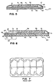
- diagnostic electrodes 20 are comprised of a foam backing layer 40 provided with an adhesive 55, upon which is mounted a tin foil layer 60 of reduced size which is itself coated with a conductive gel 75 (Figs 1,5 and 6).
- Foam backing layer 40 provides a surface which a clip 5 can bite into and thereby be securely mounted upon a tab 30 at one end of electrode 20, so that clip 5 is not easily dislodged therefrom during the operation (Figs 1, 2 and 6). While a foam material is preferred, backing layer 40 may be constructed of any fabric or material possessing a texture in which clip 5 could securely bite into.
- Foam backing layer 40 extends beyond the periphery of much of tin foil layer 60 so that adhesive 55 applied to backing 40 may enhance the ability of electrode 20 to be affixed to the patient. Also, electrodes 20 are oriented on release web 10 such that tabs 30 are arranged along the central portion thereof, so that release web 10 may be folded back upon itself to expose tabs 30 for easy engagement therewith by a clip or the user's hand (Figs 3 and 4).
- Foam backing layer 40 is made from a flexible polymeric foam material and includes a substantially rectangular body 41 and a projecting tab end or portion 47 (Figs 2 and 6). Tab end 47 is defined by an outer arcuate edge 48.
- Backing layer 40 further includes forward and rearward surfaces 51, 52, wherein forward surface 51 is completely coated with a pressure sensitive adhesive 55 (Figs 5 and 6).
- Foam layer 40 should be of a material sufficiently soft and flexible that a lead clip will bite into it securely.
- foam backing layer 40 is comprised of 6E closed cell polyethylene foam of about 1/32" (O.8mm) in thickness.
- Other polymeric foam materials or soft, somewhat thicker materials which a lead clip can bite into would be equivalent.
- the tin foil layer 60 Mounted on the adhesive forward side 51 of backing layer 40 is the tin foil layer 60, which also includes a substantially rectangular body 61 along with a projecting tab portion 67 (Figs 1, 5 and 6). Body 61 is of a reduced size relative to the size of body 41 of foam 40, and is interconnected to tab 67 by neck 64 (Fig 1). Tin foil layer 60 is provided with forward and rearward surfaces 71, 72, and is attached to backing layer 40 by adhesive 55 such that rearward surface 72 is fixed to forward surface 51 of backing layer 40. Tab portion 67 of tin foil layer 60 corresponds in size and shape with tab portion 47 of backing layer 40. Tin foil layer 60 is mounted upon backing layer 40 such that tab portion 67 directly overlies tab portion 47 to thereby define tab 30 of diagnostic electrode 20.
- Body 61 of tin foil layer 60 is of a substantially smaller dimension, in length and width, as compared with body 41 of backing layer 40.
- tin foil layer 60 When tin foil layer 60 is mounted on backing layer 40, it is substantially centred thereon, and thereby leaves around peripheral edge 62 of foil 60 a U-shaped border 44 of backing layer 40 (Fig 1). Border 44 is coated with adhesive 55 to supplement the bonding of electrode 20 to the patient, as will be discussed below.
- Conductive gel 75 is a sticky substance which, when electrode 20 is used, is pressed against the patient's body to mount diagnostic electrode 20 thereto and form the requisite contact therewith in order to gain the results of the test.
- the conductive gel provided the sole means by which diagnostic electrodes were affixed to the patients.
- This mounting arrangement is somewhat insecure and prone to accidental detaching of electrode 20 from the patient, particularly if the patient is hairy, sweaty, active etc.
- border 44 with adhesive 55, such that both conductive gel 75 and adhesive 55 are pressed against the patient, a secure mounting is achieved, even in difficult situations.
- Diagnostic electrodes 20 are collectively mounted upon a release web 10, which is preferably sufficiently stiff and rigid to be easily handled, Preferably it is made of a thin sheet of a relatively rigid plastic material. A most preferred material is a silicone coated polyester at a thickness of about 5 mils (0.13mm). Electrodes 20 are mounted with their forward surfaces 51, 71 pressed against release web 10, such that conductive gel 75 and adhesive 55 on border 44 positively engage release web 10 and affix electrodes 20 thereto.
- Electrodes 20 are preferably mounted upon release web 10 in two rows 24, 25 (Fig 1). Tabs 30 of the electrodes 20 in each row 24, 25 extend inwardly and are positioned along the central portion 11 of release web 10. Furthermore, rows 24, 25 are offset such that the longitudinal axis 27 of electrodes 20 in row 24 are aligned with outer edges 22, 23 of electrodes 20 in row 25 (Figs 1 and 2). Hence, tabs 30 of electrodes 20 in row 24 are juxtaposed and in contiguous relationship with tabs 30 of electrodes 20 in row 25, when electrodes 20 are mounted upon release web 10. Outer arcuate edges 31 of tabs 30, then, form an oscillating intersecting line 34, which is preferably generally sinusoidal in shape.
- a fold or score line 13 which is substantially parallel to rows 24, 25. Score line 13 is aligned with the middle of tabs 30 so that end portions 32 of tabs 30, from each row 24, 25, project beyond score line 13 an approximately equal distance.
- release web 10 is folded back upon itself, along score line 13, so that the portion of rearward surface 15 of release web 10, to each side of score line 13, are placed adjacent each other in engaging relation (fig 3 and 4). In this position, end portions of tabs 30 project above release web 10 to obviate the tedious procedure of peeling tab 30 from release web 10 and make it very easy to grasp or attach a clip thereto (Figs 3 and 4). Also, the offsetting of rows 24, 25 likewise offsets tabs 30, so that each tab may be easily engaged by clip 5 or the user's hand 2 without being blocked or overlapped by another tab.
- clip 5 is attached to tab 30.
- Clip 5 thereby engages foam backing layer 40 and tin foil layer 60.
- Foam backing layer 40 provides a surface which can be securely gripped by clip 5, so that clip 5 is precluded from being inadvertently dislodged from tab 30 when electrode 20 is peeled from release web 10, transferred to the patient and properly positioned on the patients's body. This works especially well with so-called alligator clips, the teeth of which bite into the foam material.
Landscapes
- Health & Medical Sciences (AREA)
- Life Sciences & Earth Sciences (AREA)
- Biomedical Technology (AREA)
- Molecular Biology (AREA)
- Dispersion Chemistry (AREA)
- Biophysics (AREA)
- Pathology (AREA)
- Engineering & Computer Science (AREA)
- Chemical & Material Sciences (AREA)
- Heart & Thoracic Surgery (AREA)
- Medical Informatics (AREA)
- Physics & Mathematics (AREA)
- Surgery (AREA)
- Animal Behavior & Ethology (AREA)
- General Health & Medical Sciences (AREA)
- Public Health (AREA)
- Veterinary Medicine (AREA)
- Electrotherapy Devices (AREA)
- Measurement And Recording Of Electrical Phenomena And Electrical Characteristics Of The Living Body (AREA)
Applications Claiming Priority (2)
| Application Number | Priority Date | Filing Date | Title |
|---|---|---|---|
| US07/129,831 US4798208A (en) | 1987-12-09 | 1987-12-09 | Diagnostic electrode |
| US129831 | 1993-09-30 |
Publications (2)
| Publication Number | Publication Date |
|---|---|
| EP0320173A2 true EP0320173A2 (fr) | 1989-06-14 |
| EP0320173A3 EP0320173A3 (fr) | 1989-09-06 |
Family
ID=22441808
Family Applications (1)
| Application Number | Title | Priority Date | Filing Date |
|---|---|---|---|
| EP88311401A Withdrawn EP0320173A3 (fr) | 1987-12-09 | 1988-12-01 | Electrode pour diagnostic |
Country Status (5)
| Country | Link |
|---|---|
| US (1) | US4798208A (fr) |
| EP (1) | EP0320173A3 (fr) |
| JP (1) | JPH024321A (fr) |
| CA (1) | CA1332383C (fr) |
| NO (1) | NO885456L (fr) |
Families Citing this family (39)
| Publication number | Priority date | Publication date | Assignee | Title |
|---|---|---|---|---|
| US5215087A (en) * | 1988-09-22 | 1993-06-01 | Minnesota Mining And Manufacturing Company | Biomedical electrode construction |
| US4890622A (en) * | 1988-10-27 | 1990-01-02 | Ferrari Robert K | Disposable biomedical electrode |
| US4911657A (en) * | 1989-03-20 | 1990-03-27 | Lec Tec Corporation | Tethered biomedical electrode connector |
| US4974594A (en) * | 1989-03-20 | 1990-12-04 | Lec Tec Corporation | Biomedical electrode and removable electrical connector |
| US5150708A (en) * | 1990-12-03 | 1992-09-29 | Spacelabs, Inc. | Tabbed defibrillator electrode pad |
| US5203330A (en) * | 1991-02-26 | 1993-04-20 | Vickers Plc | Disposable electrodes for electromyography (EMG) and nerve conduction velocity (NCV) and kit containing same |
| US5218973A (en) * | 1991-03-22 | 1993-06-15 | Staodyn, Inc. | Disposable wound treatment electrode |
| US5195523A (en) * | 1991-04-24 | 1993-03-23 | Ndm Acquisition Corp. | Medical electrode assembly |
| US5178144A (en) * | 1991-05-31 | 1993-01-12 | Ndm Acquisition Corp. | Assembly for dispensing tab electrodes |
| US5191887A (en) * | 1991-05-31 | 1993-03-09 | Ndm Acquisition Corp. | Assembly for dispensing tab electrodes |
| US5261402A (en) * | 1992-07-20 | 1993-11-16 | Graphic Controls Corporation | Snapless, tabless, disposable medical electrode with low profile |
| US5407368A (en) * | 1992-12-15 | 1995-04-18 | Minnesota Mining And Manufacturing Company | Electrode connector |
| US5454739A (en) * | 1992-12-15 | 1995-10-03 | Minnesota Mining And Manufacturing Company | Electrode connector |
| US5458141A (en) * | 1993-08-04 | 1995-10-17 | Quinton Instrument Company | Abrasive skin electrode |
| USD357069S (en) | 1993-08-25 | 1995-04-04 | Quinton Instrument Company | Medical electrode |
| US5402780A (en) * | 1993-09-02 | 1995-04-04 | Faasse, Jr.; Adrian L. | Medical electrode with offset contact stud |
| US5462157A (en) * | 1993-10-28 | 1995-10-31 | Zmd Corporation | Electrode package |
| USD377219S (en) * | 1994-06-07 | 1997-01-07 | Minnesota Mining And Manufacturing Company | Connector for a biomedical electrode |
| US5645063A (en) * | 1995-06-05 | 1997-07-08 | Quinton Instrument Company | Skin electrode having multiple conductive center members |
| US6115638A (en) * | 1998-05-04 | 2000-09-05 | Survivalink Corporation | Medical electrode with conductive release liner |
| US6223088B1 (en) * | 1998-11-09 | 2001-04-24 | Katecho, Incorporated | Electrode and connector assembly and method for using same |
| US7660621B2 (en) * | 2000-04-07 | 2010-02-09 | Medtronic, Inc. | Medical device introducer |
| AU2001285071A1 (en) * | 2000-08-17 | 2002-02-25 | John David | Trajectory guide with instrument immobilizer |
| GB2418365B (en) * | 2001-09-07 | 2006-06-14 | Desmond Bryan Mills | Contact electrode |
| US7704260B2 (en) | 2002-09-17 | 2010-04-27 | Medtronic, Inc. | Low profile instrument immobilizer |
| US7636596B2 (en) * | 2002-12-20 | 2009-12-22 | Medtronic, Inc. | Organ access device and method |
| US7896889B2 (en) * | 2003-02-20 | 2011-03-01 | Medtronic, Inc. | Trajectory guide with angled or patterned lumens or height adjustment |
| US7225009B2 (en) * | 2003-10-27 | 2007-05-29 | Chi Lin Technology Co., Ltd. | Apparatus for noninvasively measuring hematocrit and associated methods |
| WO2005079903A2 (fr) * | 2004-02-13 | 2005-09-01 | Medtronic, Inc. | Procede et appareil pour la fixation d'un dispositif d'administration therapeutique dans un trou de trepan |
| US7668604B2 (en) * | 2004-06-16 | 2010-02-23 | Conmed Corporation | Packaging for medical pads and electrodes |
| US7497863B2 (en) * | 2004-12-04 | 2009-03-03 | Medtronic, Inc. | Instrument guiding stage apparatus and method for using same |
| US7744606B2 (en) * | 2004-12-04 | 2010-06-29 | Medtronic, Inc. | Multi-lumen instrument guide |
| DE102007044019A1 (de) * | 2007-09-14 | 2009-04-09 | Dräger Medical AG & Co. KG | Medizinische Elektrode |
| US9353733B2 (en) * | 2008-12-04 | 2016-05-31 | Deep Science, Llc | Device and system for generation of power from intraluminal pressure changes |
| US11147465B2 (en) | 2015-05-05 | 2021-10-19 | Welch Allyn, Inc. | Abrasive electrode |
| USD829917S1 (en) * | 2016-08-04 | 2018-10-02 | Medline Industries, Inc. | Set of electrodes on a perforated backing sheet |
| US12012270B2 (en) * | 2018-12-20 | 2024-06-18 | Conmed Corporation | Medical electrode tear strip |
| CN113543842A (zh) * | 2019-03-07 | 2021-10-22 | 大塚制药株式会社 | 用于激活可穿戴贴片的方法和设备 |
| WO2020179922A1 (fr) * | 2019-03-07 | 2020-09-10 | Otsuka Pharmaceutical Co., Ltd. | Procédés et appareil pour un cadre entourant un timbre à porter |
Family Cites Families (7)
| Publication number | Priority date | Publication date | Assignee | Title |
|---|---|---|---|---|
| FR1524246A (fr) * | 1967-03-28 | 1968-05-10 | Thomson Medical | Perfectionnements aux dispositifs de prise de contact électrique |
| US3746004A (en) * | 1971-06-14 | 1973-07-17 | B Jankelson | Disposable electrodes for electrical stimulation of muscles and nerves of the head |
| US3842394A (en) * | 1973-03-06 | 1974-10-15 | Medical Plastics Inc | Electrical connector for plate electrode |
| DK140085B (da) * | 1976-03-29 | 1979-06-18 | Steen Brabrand Rasmussen | Engangselektrode til elektromedicinsk brug og fremgangsmåde til fremstilling af et sæt af sådanne elektroder. |
| US4640289A (en) * | 1983-11-14 | 1987-02-03 | Minnesota Mining And Manufacturing Company | Biomedical electrode |
| CA1259666A (fr) * | 1983-11-14 | 1989-09-19 | Lawrence W. Craighead | Electrode biomedicale |
| US4706680A (en) * | 1986-06-30 | 1987-11-17 | Nepera Inc. | Conductive adhesive medical electrode assemblies |
-
1987
- 1987-12-09 US US07/129,831 patent/US4798208A/en not_active Expired - Lifetime
-
1988
- 1988-11-23 CA CA000583905A patent/CA1332383C/fr not_active Expired - Fee Related
- 1988-12-01 EP EP88311401A patent/EP0320173A3/fr not_active Withdrawn
- 1988-12-08 NO NO88885456A patent/NO885456L/no unknown
- 1988-12-08 JP JP63309020A patent/JPH024321A/ja active Pending
Also Published As
| Publication number | Publication date |
|---|---|
| NO885456D0 (no) | 1988-12-08 |
| NO885456L (no) | 1989-06-12 |
| EP0320173A3 (fr) | 1989-09-06 |
| JPH024321A (ja) | 1990-01-09 |
| US4798208A (en) | 1989-01-17 |
| CA1332383C (fr) | 1994-10-11 |
Similar Documents
| Publication | Publication Date | Title |
|---|---|---|
| US4798208A (en) | Diagnostic electrode | |
| US7027877B2 (en) | Method of applying defibrilator electrode pad with folded release sheet | |
| US4635642A (en) | Medical electrode with reusable conductor | |
| EP0509710A2 (fr) | Réalisation d'une électrode biomédicale | |
| CA1246682A (fr) | Electrode biomedicale | |
| US5827184A (en) | Self-packaging bioelectrodes | |
| US5133356A (en) | Biomedical electrode having centrally-positioned tab construction | |
| US3151619A (en) | Electrode for electromedical equipment | |
| US4827939A (en) | Medical electrode with reusable conductor and method of manufacture | |
| EP0737438A2 (fr) | Electrode médicale | |
| US20260097200A1 (en) | Electrode assembly and methods | |
| JPH09501070A (ja) | 除細動器電極システム | |
| US5191887A (en) | Assembly for dispensing tab electrodes | |
| EP0142372B1 (fr) | Electrode bio-médicale | |
| US20110066021A1 (en) | Medical Electrode with Self-Lifting Tabs | |
| JP5193928B2 (ja) | 生体電極パッド及び生体電極 | |
| US6341230B1 (en) | Biomedical electrode | |
| US5226225A (en) | Method of making a biomedical electrode | |
| US5178144A (en) | Assembly for dispensing tab electrodes | |
| JP5612051B2 (ja) | 生体電極用の粘着パッド及び粘着パッドシート | |
| JPH09271467A (ja) | 生体用電極 | |
| JPH0856983A (ja) | 医療用目盛付粘着テープ | |
| HK40065140A (en) | Electrode assembly and methods |
Legal Events
| Date | Code | Title | Description |
|---|---|---|---|
| PUAI | Public reference made under article 153(3) epc to a published international application that has entered the european phase |
Free format text: ORIGINAL CODE: 0009012 |
|
| AK | Designated contracting states |
Kind code of ref document: A2 Designated state(s): DE FR GB |
|
| PUAL | Search report despatched |
Free format text: ORIGINAL CODE: 0009013 |
|
| AK | Designated contracting states |
Kind code of ref document: A3 Designated state(s): DE FR GB |
|
| 17P | Request for examination filed |
Effective date: 19900305 |
|
| 17Q | First examination report despatched |
Effective date: 19921006 |
|
| STAA | Information on the status of an ep patent application or granted ep patent |
Free format text: STATUS: THE APPLICATION IS DEEMED TO BE WITHDRAWN |
|
| 18D | Application deemed to be withdrawn |
Effective date: 19940310 |