EP0320181A2 - Système de télévision par câble avec liaison à fibre optique utilisée en commun - Google Patents
Système de télévision par câble avec liaison à fibre optique utilisée en commun Download PDFInfo
- Publication number
- EP0320181A2 EP0320181A2 EP88311444A EP88311444A EP0320181A2 EP 0320181 A2 EP0320181 A2 EP 0320181A2 EP 88311444 A EP88311444 A EP 88311444A EP 88311444 A EP88311444 A EP 88311444A EP 0320181 A2 EP0320181 A2 EP 0320181A2
- Authority
- EP
- European Patent Office
- Prior art keywords
- terminal
- service request
- signals
- subscriber terminals
- signal
- Prior art date
- Legal status (The legal status is an assumption and is not a legal conclusion. Google has not performed a legal analysis and makes no representation as to the accuracy of the status listed.)
- Withdrawn
Links
Images

Classifications
-
- H—ELECTRICITY
- H04—ELECTRIC COMMUNICATION TECHNIQUE
- H04N—PICTORIAL COMMUNICATION, e.g. TELEVISION
- H04N7/00—Television systems
- H04N7/16—Analogue secrecy systems; Analogue subscription systems
-
- H—ELECTRICITY
- H04—ELECTRIC COMMUNICATION TECHNIQUE
- H04H—BROADCAST COMMUNICATION
- H04H20/00—Arrangements for broadcast or for distribution combined with broadcast
- H04H20/65—Arrangements characterised by transmission systems for broadcast
- H04H20/69—Optical systems
-
- H—ELECTRICITY
- H04—ELECTRIC COMMUNICATION TECHNIQUE
- H04N—PICTORIAL COMMUNICATION, e.g. TELEVISION
- H04N7/00—Television systems
- H04N7/10—Adaptations for transmission by electrical cable
-
- H—ELECTRICITY
- H04—ELECTRIC COMMUNICATION TECHNIQUE
- H04N—PICTORIAL COMMUNICATION, e.g. TELEVISION
- H04N7/00—Television systems
- H04N7/16—Analogue secrecy systems; Analogue subscription systems
- H04N7/173—Analogue secrecy systems; Analogue subscription systems with two-way working, e.g. subscriber sending a programme selection signal
- H04N7/17345—Control of the passage of the selected programme
-
- H—ELECTRICITY
- H04—ELECTRIC COMMUNICATION TECHNIQUE
- H04N—PICTORIAL COMMUNICATION, e.g. TELEVISION
- H04N7/00—Television systems
- H04N7/22—Adaptations for optical transmission
Definitions
- the present invention generally pertains to electronic communication systems and is particularly directed to the use of fiber optics in cable television (CATV) systems.
- CATV cable television
- a plurality of video signals from separate video signal sources are amplitude modulated onto a plurality of carriers and then multiplexed to provide a multiplexed electrical signal.
- the multiplexed electrical signal is then transmitted to a distribution terminal from which it is further transmitted to each of a plurality of subscriber terminals over a corresponding plurality of coaxial cables that couple the distribution terminal to the plurality of subscriber terminals.
- Service request signals generated in the subscriber terminals typically are transmitted back to the headend terminal over telephone lines.
- optical fibers to transmit television signals in CATV systems has been suggested because of the superior long-distance transmission characteristics of optical fibers in comparison with the long-distance transmission characteristics of coaxial cable.
- Service request signals from the plurality of subscriber terminals are provided over separate fiber optic links to a second multimode splitter which transmits the service request signals over a multimode optical fiber to the central office.
- a switch used for multiplexing the signals at the central office is controlled in response to the service request signals.
- the present invention provides an economical CATV system that uses a single optical fiber for transmitting information signals, such as video signals, for a plurality of subscriber terminals from a headend terminal to a distribution terminal, and converts the transmitted signals at the distribution terminal into electrical signals for distribution to the plurality of subscriber terminals over a plurality of electrical signal conduits, such as coaxial cables.
- the CATV system of the present invention thereby utilizes the superior long distance transmission characteristics of optical fibers for the link between the headend terminal and the distribution terminal, and utilizes the lower cost coaxial cable for the plurality of links between the distribution terminal and the subscriber terminals where the length of such links is such that the difference in transmission characteristics between coaxial cable and optical fibers is not as significant.
- the CATV system of the present invention comprises a headend terminal that includes means for providing a plurality of video signals for a plurality of subscribers; switch means for selecting the plurality of video signals to provide a multiplexed electrical signal; and means for converting the multiplexed electrical signal into a multiplexed optical signal for transmission; a single optical fiber for carrying the transmitted multiplexed optical signal from the converter to the distribution terminal; and a distribution terminal that includes means for receiving said transmitted multiplexed optical signal and for converting it into a multiplexed electrical signal for distribution to the different subscriber terminals. Accordingly, preexisting CATV systems that use coaxial cable throughout their distribution links may be readily retrofitted with the system of the present invention without having to replace the coaxial cable links from the distribution terminal to the subscriber terminals.
- the distribution terminal further includes means for receiving electrical service request signals from each of said plurality of subscriber terminals, and means for converting each received service request signal into an optical service request signal for transmission to the headend terminal;
- the system further includes an optical fiber for transmitting to the headend terminal from the distribution terminal a plurality of said optical service request signals converted from said service request signals received by the distribution terminal from said plurality of subscriber terminals;
- the headend terminal further comprises means for receiving each said transmitted optical service request signal and for converting it into an electrical service request signal for processing by the headend terminal.
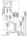
- a preferred embodiment of a CATV system includes a headend terminal 10, a single-mode optical fiber 11, a multimode optical fiber 12, a distribution terminal 13, a plurality of coaxial cables 14 and a plurality of subscriber terminals 15. It is to be understood that the system may further include additional distribution terminals, with a plurality of additional subscriber terminals being coupled to each of the additional distribution terminals by coaxial cables in the manner shown in the Drawing, and with each distribution terminal being coupled to the headend terminal 10 by a separate single-mode optical fiber.
- the headend terminal 10 includes a plurality of FM modulators and line drivers 16, a plurality of digital switches 18, a plurality of upconverters 20, a signal combining unit 22, a laser diode 24 for each distribution terminal 13, a PIN diode 26 for each distribution terminal 13, a switch control unit 28, and, optionally, a telephone system interface unit 30.
- Each distribution terminal 13 includes a PIN FET 40, an amplifier 42, a power splitter 44, a light emitting diode (LED) 46, a channel control interface unit 48, and, optionally, a telephone system interface unit 50.
- Each subscriber terminal 14 includes a power splitter 60, one or more subscriber equipment sets 62, and one or more telephones 64.
- Each subscriber equipment set 62 includes a tuner 66, an FM demodulator 68, a remote control unit (RCU) 70, and infrared (IR) receiver 72, and a modulator 74.
- RCU remote control unit
- IR infrared
- a plurality of video signals 17 from various video sources are frequency modulated onto frequency modulated (FM) carriers by the FM modulators and line drivers 16.
- the switches 18 select twelve of the video signals 17 and provide them as frequency-division-multiplexed video signals to the signal combining unit 22 via the upconvertors 20.
- An FM signal carrying twelve multiplexed video signals is then provided to the laser diode 24, which converts the combined multiplexed signals into an optical multiplexed signal for transmission over the single-mode optical fiber 11.
- the single-mode optical fiber 11 is connected to the laser diode 24 for transmitting an optical signal containing twelve multiplexed video signals for a plurality of subscriber terminals 15.
- the PIN FET 40 is connected to the single-mode optical fiber 11 for receiving the optical multiplexed signal transmitted over the single-mode optical fiber 11 and for converting the received optical signal into an electrical multiplexed signal.
- the electrical signal from the PIN FET 40 is amplified by the amplifier 42 and provided to the power splitter 44.
- the power splitter 44 further conditions the amplified multiplexed electrical signal for transmission to the subscriber terminals 15 over the respective coaxial cables 14.
- Each subscriber terminal 15 contains one or more sets of subscriber equipment 62.
- the power splitter 60 in each subscriber terminal 15 provides the signal received over the respective coaxial cable 14 to the different subscriber equipment sets 62.
- the received video signals are passed through the tuner 66, which is tuned to select one of the frequency-division-multiplexed video signals for viewing, and then through the FM demodulator 68 to provide the selected video signal 69.
- the remote control unit (RCU) 70 is operated.
- the RCU provides a coded infrared (IR) signal which is detected by the IR receiver 72, which in turn converts the received IR signal into an electrical signal.
- the modulator 74 modulates the service request signal for transmission back over the coaxial cable 14 to the distribution terminal 13.
- service request signals received from the subscriber terminals 15 are provided to the channel control interface unit 48, which provides the service request signals to the LED 46.
- the LED 46 converts the service request signals from the channel control interface unit 48 into optical service request signals.
- the multimode optical fiber 12 is connected to the LED 46 for transmitting the optical service request signals to the headend terminal 10, where they are received by the PIN diode 26 and converted into electrical service request signals.
- the switch control unit 28 processes the service request signal converted by the PIN diode 26 and provides switching signals on line 29 for controlling the switches 18 in accordance with such service request signals.
- CATV system sometimes also provide telephone services.
- the CATV system described herein optionally includes equipment for providing television services together with the CATV services.
- the telephone system interface unit 30 receives and sends telephone signals 31 from and to telephone lines (not shown).
- the interface unit 30 conditions received telephone signals for combination by the signal combining unit 22 with a group of twelve multiplexed video signals.
- the telephone signals are likewise converted to optical signals and transmitted over a single-mode optical fiber 11 to the distribution terminal 13, where after reconversion to electrical signals by the PIN FET 40, the telephone signals are transferred by the power splitter 44 to the telephone system interface unit 50.
- Telephone signals are communicated between the interface unit 50 and the telephones 64 in the subscriber terminals 15 via twisted pairs 51.
- Telephone signals from the subscriber terminals 15 are provided by the interface unit 50 to the LED 46, which converts such telephone signals into optical telephone signals for transmission over the multimode optical fiber 12 to the PIN diode 26 in the headend terminal 10.
- the PIN diode 26 converts the optical telephone signals into electrical telephone signals and provides the same to the telephone interface unit 30 which sends such telephone signals 31 over the telephone lines.
Landscapes
- Engineering & Computer Science (AREA)
- Signal Processing (AREA)
- Multimedia (AREA)
- Two-Way Televisions, Distribution Of Moving Picture Or The Like (AREA)
- Optical Communication System (AREA)
- Electric Cable Installation (AREA)
Applications Claiming Priority (2)
| Application Number | Priority Date | Filing Date | Title |
|---|---|---|---|
| US13181287A | 1987-12-11 | 1987-12-11 | |
| US131812 | 1993-10-05 |
Publications (2)
| Publication Number | Publication Date |
|---|---|
| EP0320181A2 true EP0320181A2 (fr) | 1989-06-14 |
| EP0320181A3 EP0320181A3 (fr) | 1990-12-05 |
Family
ID=22451134
Family Applications (1)
| Application Number | Title | Priority Date | Filing Date |
|---|---|---|---|
| EP19880311444 Withdrawn EP0320181A3 (fr) | 1987-12-11 | 1988-12-02 | Système de télévision par câble avec liaison à fibre optique utilisée en commun |
Country Status (7)
| Country | Link |
|---|---|
| EP (1) | EP0320181A3 (fr) |
| JP (1) | JPH022796A (fr) |
| KR (1) | KR890011441A (fr) |
| AU (1) | AU2668088A (fr) |
| DK (1) | DK687588A (fr) |
| IL (1) | IL88476A0 (fr) |
| NO (1) | NO885496L (fr) |
Cited By (2)
| Publication number | Priority date | Publication date | Assignee | Title |
|---|---|---|---|---|
| EP0419137A3 (en) * | 1989-09-19 | 1992-04-15 | General Instrument Corporation | Dynamically responsive catv system with shared fiber optic link |
| WO2000051270A1 (fr) * | 1999-02-22 | 2000-08-31 | Scientific-Atlanta, Inc. | Emetteur optique numerique a module numerique amovible |
Families Citing this family (2)
| Publication number | Priority date | Publication date | Assignee | Title |
|---|---|---|---|---|
| JPS6124913U (ja) * | 1984-07-19 | 1986-02-14 | 小原金属工業株式会社 | ロボツト溶接用ケ−ブル |
| JPH0286384A (ja) * | 1988-09-22 | 1990-03-27 | Pioneer Electron Corp | 動画像情報サービスシステム及び該システム用ヘッドエンド装置 |
Family Cites Families (3)
| Publication number | Priority date | Publication date | Assignee | Title |
|---|---|---|---|---|
| US4506387A (en) * | 1983-05-25 | 1985-03-19 | Walter Howard F | Programming-on-demand cable system and method |
| JPS60130285A (ja) * | 1983-12-16 | 1985-07-11 | Pioneer Electronic Corp | Catvにおける端末システム |
| DE3403206A1 (de) * | 1984-01-31 | 1985-08-01 | Standard Elektrik Lorenz Ag, 7000 Stuttgart | Lichtwellenleiter-verteilnetz fuer fernseh- und tonprogramme |
-
1988
- 1988-11-24 IL IL88476A patent/IL88476A0/xx unknown
- 1988-12-02 EP EP19880311444 patent/EP0320181A3/fr not_active Withdrawn
- 1988-12-07 KR KR1019880016250A patent/KR890011441A/ko not_active Withdrawn
- 1988-12-08 AU AU26680/88A patent/AU2668088A/en not_active Abandoned
- 1988-12-09 DK DK687588A patent/DK687588A/da not_active Application Discontinuation
- 1988-12-09 NO NO88885496A patent/NO885496L/no unknown
- 1988-12-09 JP JP63311780A patent/JPH022796A/ja active Pending
Cited By (2)
| Publication number | Priority date | Publication date | Assignee | Title |
|---|---|---|---|---|
| EP0419137A3 (en) * | 1989-09-19 | 1992-04-15 | General Instrument Corporation | Dynamically responsive catv system with shared fiber optic link |
| WO2000051270A1 (fr) * | 1999-02-22 | 2000-08-31 | Scientific-Atlanta, Inc. | Emetteur optique numerique a module numerique amovible |
Also Published As
| Publication number | Publication date |
|---|---|
| EP0320181A3 (fr) | 1990-12-05 |
| JPH022796A (ja) | 1990-01-08 |
| KR890011441A (ko) | 1989-08-14 |
| NO885496D0 (no) | 1988-12-09 |
| DK687588A (da) | 1989-06-12 |
| AU2668088A (en) | 1989-06-15 |
| NO885496L (no) | 1989-06-12 |
| IL88476A0 (en) | 1989-06-30 |
| DK687588D0 (da) | 1988-12-09 |
Similar Documents
| Publication | Publication Date | Title |
|---|---|---|
| US5136411A (en) | Dynamically responsive CATV system with shared fiber optic link | |
| US4891694A (en) | Fiber optic cable television distribution system | |
| US5202780A (en) | Optical communication system for the subscriber area | |
| AU707951B2 (en) | Optical transmission system | |
| US4709418A (en) | Wideband cable network | |
| JP3133597B2 (ja) | 光伝送有線放送システム | |
| US4686667A (en) | Broadband integrated subscriber loop system | |
| US6538781B1 (en) | Multimedia distribution system using fiber optic lines | |
| US7127170B2 (en) | Optical frequency division multiplexing network | |
| AU671913B2 (en) | Cable television distribution | |
| JPS5925440A (ja) | テレビジヨン信号用分配ネツトワ−ク | |
| CA1160771A (fr) | Systeme de transmission numerique integre au service | |
| EP0690651A2 (fr) | Réseau à commutateur optique à division spatiale et terminal | |
| US6281996B1 (en) | Optical network termination unit of a hybrid fiber/coax access network | |
| EP0320181A2 (fr) | Système de télévision par câble avec liaison à fibre optique utilisée en commun | |
| EP1235434B1 (fr) | Reseau à deux voix pour la distribution de signaux à des locaux utilisant des fibres optiques | |
| CA1241993A (fr) | Systeme de transmission a boucle fermee | |
| KR960010489B1 (ko) | 소형의 분배 센터들로 이루어지는 디지틀 씨.에이.티.브이 시스템 | |
| JPS6212222A (ja) | 波長多重光伝送装置 | |
| US20020124265A1 (en) | Equipment for distributing an optical signal | |
| KR100697865B1 (ko) | 통신 및 방송 신호 통합 광전송 시스템 | |
| JP2002084535A (ja) | 光加入者線終端装置 | |
| JPH0823309A (ja) | 双方向光catvシステムおよび双方向通信方法 | |
| KR20040047037A (ko) | Catv 시스템의 하향채널을 이용한 가입자망 관리 장치 |
Legal Events
| Date | Code | Title | Description |
|---|---|---|---|
| PUAI | Public reference made under article 153(3) epc to a published international application that has entered the european phase |
Free format text: ORIGINAL CODE: 0009012 |
|
| AK | Designated contracting states |
Kind code of ref document: A2 Designated state(s): AT BE CH DE ES FR GB GR IT LI NL SE |
|
| PUAL | Search report despatched |
Free format text: ORIGINAL CODE: 0009013 |
|
| AK | Designated contracting states |
Kind code of ref document: A3 Designated state(s): AT BE CH DE ES FR GB GR IT LI NL SE |
|
| STAA | Information on the status of an ep patent application or granted ep patent |
Free format text: STATUS: THE APPLICATION IS DEEMED TO BE WITHDRAWN |
|
| 18D | Application deemed to be withdrawn |
Effective date: 19910606 |
|
| P01 | Opt-out of the competence of the unified patent court (upc) registered |
Effective date: 20230522 |