EP0320190A2 - Lehmbrecher - Google Patents
Lehmbrecher Download PDFInfo
- Publication number
- EP0320190A2 EP0320190A2 EP88311503A EP88311503A EP0320190A2 EP 0320190 A2 EP0320190 A2 EP 0320190A2 EP 88311503 A EP88311503 A EP 88311503A EP 88311503 A EP88311503 A EP 88311503A EP 0320190 A2 EP0320190 A2 EP 0320190A2
- Authority
- EP
- European Patent Office
- Prior art keywords
- rotors
- machine according
- rotor
- crushing
- grid
- Prior art date
- Legal status (The legal status is an assumption and is not a legal conclusion. Google has not performed a legal analysis and makes no representation as to the accuracy of the status listed.)
- Ceased
Links
- 239000004927 clay Substances 0.000 title claims description 12
- 229910052500 inorganic mineral Inorganic materials 0.000 claims abstract description 9
- 239000011707 mineral Substances 0.000 claims abstract description 9
- 238000004513 sizing Methods 0.000 claims abstract description 6
- 239000000463 material Substances 0.000 claims abstract description 3
- 239000000126 substance Substances 0.000 claims description 7
- 238000013459 approach Methods 0.000 claims description 4
- 230000002093 peripheral effect Effects 0.000 claims description 2
- 238000000034 method Methods 0.000 abstract description 5
- 239000002245 particle Substances 0.000 description 4
- 238000012423 maintenance Methods 0.000 description 3
- 230000008030 elimination Effects 0.000 description 1
- 238000003379 elimination reaction Methods 0.000 description 1
- 239000012634 fragment Substances 0.000 description 1
- 238000004519 manufacturing process Methods 0.000 description 1
- 238000003825 pressing Methods 0.000 description 1
- 230000000284 resting effect Effects 0.000 description 1
Images

Classifications
-
- B—PERFORMING OPERATIONS; TRANSPORTING
- B28—WORKING CEMENT, CLAY, OR STONE
- B28C—PREPARING CLAY; PRODUCING MIXTURES CONTAINING CLAY OR CEMENTITIOUS MATERIAL, e.g. PLASTER
- B28C1/00—Apparatus or methods for obtaining or processing clay
- B28C1/10—Apparatus or methods for obtaining or processing clay for processing clay-containing substances in non-fluid condition ; Plants
- B28C1/14—Apparatus or methods for obtaining or processing clay for processing clay-containing substances in non-fluid condition ; Plants specially adapted for homogenising, comminuting or conditioning clay in non-fluid condition or for separating undesired admixtures therefrom
- B28C1/18—Apparatus or methods for obtaining or processing clay for processing clay-containing substances in non-fluid condition ; Plants specially adapted for homogenising, comminuting or conditioning clay in non-fluid condition or for separating undesired admixtures therefrom for comminuting clay lumps
- B28C1/187—Apparatus or methods for obtaining or processing clay for processing clay-containing substances in non-fluid condition ; Plants specially adapted for homogenising, comminuting or conditioning clay in non-fluid condition or for separating undesired admixtures therefrom for comminuting clay lumps using co-operating rotating elements, e.g. cutters
-
- B—PERFORMING OPERATIONS; TRANSPORTING
- B02—CRUSHING, PULVERISING, OR DISINTEGRATING; PREPARATORY TREATMENT OF GRAIN FOR MILLING
- B02C—CRUSHING, PULVERISING, OR DISINTEGRATING IN GENERAL; MILLING GRAIN
- B02C4/00—Crushing or disintegrating by roller mills
- B02C4/02—Crushing or disintegrating by roller mills with two or more rollers
-
- B—PERFORMING OPERATIONS; TRANSPORTING
- B02—CRUSHING, PULVERISING, OR DISINTEGRATING; PREPARATORY TREATMENT OF GRAIN FOR MILLING
- B02C—CRUSHING, PULVERISING, OR DISINTEGRATING IN GENERAL; MILLING GRAIN
- B02C4/00—Crushing or disintegrating by roller mills
- B02C4/28—Details
Definitions
- the invention relates to machines for the crushing of mineral substances and in particular of various types of clay.
- Clay whether in the form of marl, which is substantially wet, or of shale which is relatively dry, is generally quarried or otherwise extracted in lumps of very varied size, and hither to a crushing machine has been employed to break the largest lumps down to a manageable size, and a further machine, such as a wet pan mill, has been required to reduce the particle size down to something of the order of 9 mm so as to prepare it for subsequent process such as brick-making.
- a machine for the crushing and sizing of mineral substances such as clay comprising a pair of parallel rotors defining between them a crushing gap, and perforated grids means spaced from at least one of the said rotors so as to define a sizing gap therebetween, and means for driving the rotors to crush lumps of mineral introduced therebetween and to press the thus-crushed material through the perforations of said grid.
- each of the rotors is of such multi-lobal section transverse to the axis and is fixed to the axis of the rotor in such an angular position that the closest distance between the surface of mutually aligned portions remains constant as the rotors rotate.
- the rotors are tri-lobal in section.
- the surface of each of the the rotors comprises two or more length portions, the length portions of one rotor being aligned with the length portions of the other so that the surfaces defines by mutually aligned portions exert a crushing action on the lumps of mineral substance.
- the machine primarily consists of two rotors, 2 and 4 mounted for rotation about horizontal axis 8 within a housing 6.
- the housing 6 is provided with access doors 34 and an opening 10 above and between the rotors for the introduction of clay lumps to be treated.
- pillars 12 spaced apart lengthwise of the rotors.
- the pillars support a horizontal axis 14 upon which are pivoted two similarly spaced pairs of arcuate plates 16, one pair being under each of the rotors. Between the plates of each pair extends a grid 18 which is slotted lengthwise, that is to say perpendicularly to the axes 8.
- one of the plates 16 is shown connected at its end remote from axis 14 to the ram of a vertically mounted pneumatic cylinder 20.
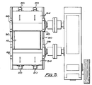
- the other of the plates 16 associated with rotor 2, not shown in Fig. 1, is also connected to a pneumatic cylinder 20 shown in Fig. 3.
- the grid 18 is seen to be close to the under-side of the rotor 2 and as will be explained later the juxtaposition of the grid and the turning rotor results in a pressing of the clay substance through the slots of the grid.
- a pin (not shown) has been removed which connected the eye 22 of the shackle 26 of the ram of the cylinder 20 to the hole 24 in the end of one of the plates 16, so that the plate has swung downwardly about the pivot 14 for access to the grid 18 for maintenance purposes.
- each end of the rotors 2, 4 are wear plates 28 and, between the individual rotors are further wear plates 30.
- an upwardly convex plate 32 is arranged to direct clay particles that have passed downwardly between the rotors onto one or other of the grids 18.
- the transverse section of the rotors has a generally trilobal shape, and is made of three similarly shaped segments 40, and six segments 42, similar to one another but different from the segments 40.
- the segments 42 are arranged in pairs, one of which is reversed relative to the other, between two segments 40.
- the peripheral surface of each of the segments is provided with axial grooves 44.
- rotor 4 The shape of rotor 4 is shown only in outline, but it will be observed that, not only is it of the same tri-lobal shape as rotor 2, but the parts of the circumference of largest diameter occupy the same angular position as in rotor 2.
- the rotors are arranged to rotate, however, in opposite directions, the rotor 2 anticlockwise as shown in the figure, and the rotor 4 clockwise.
- the periphery of rotor 2 nearest to rotor 4 is almost at the centre line between the axes 8, the radius being a maximum at that point, whilst the radius of rotor 4 is a minimum at the point of nearest approach to rotor 2, and is remote from the centre line by a distance which experience shows corresponds to the maximum particle size that can conveniently be pressed through the grids 18.
- any clay lumps introduced between them which are of size greater than the constant spacing between the rotors become crushed, the fragments falling onto the plate 32 and thence being directed to the grids 18 for further treatment.
- the grid could be arranged to be forced downwardly about the axis 14 under the control of the cylinder 20 which would then subsequently restore the grid to its original position, though the prime function of the cylinders is to lower the grids 18 for maintenance.
- the above description applies, of course, to both rotors.
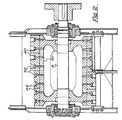
- each is formed in two lengthwise portion as will be seen from Fig. 2 which shows a section of one of the rotors, it being understood that the other is similar.
- the rotor is formed of a hollow shell 50 locked to the shaft 8 and carrying, externally, the segments 40 and 42, secured thereto by bolts 52.
- the surface of the rotor is divided lengthwise into two halves, one half being of maximum radius where the other half is of minimum radius.
- each half of each rotor is made of two segments 40 (or, as it were 42) arranged lengthwise. It will be understood that each half-length of each rotor is exactly like the other half-length but displaced by 60 degrees about the axis. Moreover the relationship between the respective rotors described above applies equally to the respective half-lengths thereof.
Landscapes
- Engineering & Computer Science (AREA)
- Food Science & Technology (AREA)
- Chemical & Material Sciences (AREA)
- Dispersion Chemistry (AREA)
- Crushing And Pulverization Processes (AREA)
Applications Claiming Priority (2)
| Application Number | Priority Date | Filing Date | Title |
|---|---|---|---|
| GB8728512 | 1987-12-05 | ||
| GB878728512A GB8728512D0 (en) | 1987-12-05 | 1987-12-05 | Clay crushing machine |
Publications (2)
| Publication Number | Publication Date |
|---|---|
| EP0320190A2 true EP0320190A2 (de) | 1989-06-14 |
| EP0320190A3 EP0320190A3 (de) | 1990-01-24 |
Family
ID=10628077
Family Applications (1)
| Application Number | Title | Priority Date | Filing Date |
|---|---|---|---|
| EP88311503A Ceased EP0320190A3 (de) | 1987-12-05 | 1988-12-05 | Lehmbrecher |
Country Status (3)
| Country | Link |
|---|---|
| US (1) | US4971260A (de) |
| EP (1) | EP0320190A3 (de) |
| GB (1) | GB8728512D0 (de) |
Cited By (2)
| Publication number | Priority date | Publication date | Assignee | Title |
|---|---|---|---|---|
| EP0402545B1 (de) * | 1989-06-16 | 1993-09-15 | Kabushiki Kaisha Iseki Kaihatsu Koki | Zerkleinerungsmaschine |
| CN108687952A (zh) * | 2018-05-22 | 2018-10-23 | 中国矿业大学 | 一种水泥破壳装置及混凝土生产系统 |
Families Citing this family (6)
| Publication number | Priority date | Publication date | Assignee | Title |
|---|---|---|---|---|
| US6203297B1 (en) | 1999-09-29 | 2001-03-20 | Dresser Equipment Group, Inc. | Fluid flow device with improved cooling system and method for cooling a vacuum pump |
| US7131606B2 (en) | 2000-10-30 | 2006-11-07 | Badger Bite Co. | Comminution blade |
| US7500630B2 (en) * | 2000-10-30 | 2009-03-10 | Badger Shredding Products, Inc. | Reversible blade for a comminution machine |
| AUPR912601A0 (en) * | 2001-11-27 | 2001-12-20 | Oldenburg Australasia Pty Ltd | A dual product sizing machine |
| CN112439486A (zh) * | 2019-08-29 | 2021-03-05 | 徐州市贾汪区金牛彩砖有限公司 | 一种用于砖块加工的原料筛选设备 |
| CN113058687A (zh) * | 2021-04-28 | 2021-07-02 | 江苏鹏飞集团股份有限公司 | 辊面再利用的辊压装置 |
Family Cites Families (4)
| Publication number | Priority date | Publication date | Assignee | Title |
|---|---|---|---|---|
| US271588A (en) * | 1883-02-06 | Clay reducer and disintegrator | ||
| CH37006A (de) * | 1906-08-01 | 1907-03-31 | Franz Gysler | Walzwerk für Tonindustrie |
| US3722805A (en) * | 1971-08-06 | 1973-03-27 | American Pulverizer | Grate for reduction mill |
| DE2346159C2 (de) * | 1973-09-13 | 1985-03-07 | Karl Händle & Söhne Maschinenfabrik u. Eisengießerei, GmbH & Co KG, 7130 Mühlacker | Knetraspler für Ton oder tonähnliche Massen |
-
1987
- 1987-12-05 GB GB878728512A patent/GB8728512D0/en active Pending
-
1988
- 1988-12-05 EP EP88311503A patent/EP0320190A3/de not_active Ceased
-
1990
- 1990-01-09 US US07/463,145 patent/US4971260A/en not_active Expired - Fee Related
Cited By (2)
| Publication number | Priority date | Publication date | Assignee | Title |
|---|---|---|---|---|
| EP0402545B1 (de) * | 1989-06-16 | 1993-09-15 | Kabushiki Kaisha Iseki Kaihatsu Koki | Zerkleinerungsmaschine |
| CN108687952A (zh) * | 2018-05-22 | 2018-10-23 | 中国矿业大学 | 一种水泥破壳装置及混凝土生产系统 |
Also Published As
| Publication number | Publication date |
|---|---|
| US4971260A (en) | 1990-11-20 |
| EP0320190A3 (de) | 1990-01-24 |
| GB8728512D0 (en) | 1988-01-13 |
Similar Documents
| Publication | Publication Date | Title |
|---|---|---|
| US4243182A (en) | Liner assembly for ball mills | |
| Romanovich et al. | Determination of rational parameters for process of grinding materials pre-crushed by pressure in ball mill | |
| US5078327A (en) | Device for the processing of materials | |
| US4971260A (en) | Clay crushing machine | |
| US2261257A (en) | Machine for treating plastic masses and fibrous materials | |
| US4951887A (en) | Screw mill for comminuting and compressing material for grinding | |
| US5247879A (en) | Nut cracking machine | |
| WO2012125834A2 (en) | Conjugate anvil hammer mill | |
| CN101142024B (zh) | 用于锥形偏心驱动破碎机中的破碎的方法 | |
| CN212441555U (zh) | 一种固料简易粉碎装置 | |
| US2654294A (en) | Pulp shredding and treating machine | |
| HU207001B (en) | Chipping apparatus for chipping crushable and/or shreddable materials | |
| US4073032A (en) | Nut cracking machine | |
| CN1053563A (zh) | 筒辊磨机 | |
| US5362001A (en) | Apparatus for pulverizing rubber scrap | |
| EP2319624B1 (de) | Verfahren zum feinen zerstossen von klumpigem material | |
| US5406865A (en) | Method for producing one-piece cutter body members for comminuting apparatus | |
| US4017356A (en) | Apparatus and method for manufacturing wood pulp by grinding wood block material | |
| CN208824580U (zh) | 一种熔融石英生产用破碎装置 | |
| DE3837766C2 (de) | ||
| RU186478U1 (ru) | Вибровалковый измельчитель-активатор | |
| CN2124065U (zh) | 组合式双腔回转超细碎机 | |
| WO1994015713A1 (en) | A jaw crusher, particularly a stone crusher | |
| JPH10296106A (ja) | 破砕機 | |
| US1923013A (en) | Apparatus for the preparation of semicolloids and uniform colloids |
Legal Events
| Date | Code | Title | Description |
|---|---|---|---|
| PUAI | Public reference made under article 153(3) epc to a published international application that has entered the european phase |
Free format text: ORIGINAL CODE: 0009012 |
|
| AK | Designated contracting states |
Kind code of ref document: A2 Designated state(s): DE ES FR GB IT |
|
| PUAL | Search report despatched |
Free format text: ORIGINAL CODE: 0009013 |
|
| AK | Designated contracting states |
Kind code of ref document: A3 Designated state(s): DE ES FR GB IT |
|
| 17P | Request for examination filed |
Effective date: 19900314 |
|
| 17Q | First examination report despatched |
Effective date: 19901105 |
|
| STAA | Information on the status of an ep patent application or granted ep patent |
Free format text: STATUS: THE APPLICATION HAS BEEN REFUSED |
|
| 18R | Application refused |
Effective date: 19930722 |