EP0320212A2 - Identifikationszeichner - Google Patents
Identifikationszeichner Download PDFInfo
- Publication number
- EP0320212A2 EP0320212A2 EP88311547A EP88311547A EP0320212A2 EP 0320212 A2 EP0320212 A2 EP 0320212A2 EP 88311547 A EP88311547 A EP 88311547A EP 88311547 A EP88311547 A EP 88311547A EP 0320212 A2 EP0320212 A2 EP 0320212A2
- Authority
- EP
- European Patent Office
- Prior art keywords
- identification
- marker
- grip
- top surface
- golf club
- Prior art date
- Legal status (The legal status is an assumption and is not a legal conclusion. Google has not performed a legal analysis and makes no representation as to the accuracy of the status listed.)
- Granted
Links
Images


Classifications
-
- A—HUMAN NECESSITIES
- A63—SPORTS; GAMES; AMUSEMENTS
- A63B—APPARATUS FOR PHYSICAL TRAINING, GYMNASTICS, SWIMMING, CLIMBING, OR FENCING; BALL GAMES; TRAINING EQUIPMENT
- A63B57/00—Golfing accessories
- A63B57/30—Markers
- A63B57/353—Golf ball position markers
-
- A—HUMAN NECESSITIES
- A63—SPORTS; GAMES; AMUSEMENTS
- A63B—APPARATUS FOR PHYSICAL TRAINING, GYMNASTICS, SWIMMING, CLIMBING, OR FENCING; BALL GAMES; TRAINING EQUIPMENT
- A63B53/00—Golf clubs
- A63B53/007—Putters
-
- A—HUMAN NECESSITIES
- A63—SPORTS; GAMES; AMUSEMENTS
- A63B—APPARATUS FOR PHYSICAL TRAINING, GYMNASTICS, SWIMMING, CLIMBING, OR FENCING; BALL GAMES; TRAINING EQUIPMENT
- A63B53/00—Golf clubs
- A63B53/14—Handles
-
- A—HUMAN NECESSITIES
- A63—SPORTS; GAMES; AMUSEMENTS
- A63B—APPARATUS FOR PHYSICAL TRAINING, GYMNASTICS, SWIMMING, CLIMBING, OR FENCING; BALL GAMES; TRAINING EQUIPMENT
- A63B57/00—Golfing accessories
- A63B57/20—Holders, e.g. of tees or of balls
- A63B57/207—Golf ball position marker holders
-
- A—HUMAN NECESSITIES
- A63—SPORTS; GAMES; AMUSEMENTS
- A63B—APPARATUS FOR PHYSICAL TRAINING, GYMNASTICS, SWIMMING, CLIMBING, OR FENCING; BALL GAMES; TRAINING EQUIPMENT
- A63B60/00—Details or accessories of golf clubs, bats, rackets or the like
- A63B60/06—Handles
- A63B60/16—Caps; Ferrules
-
- F—MECHANICAL ENGINEERING; LIGHTING; HEATING; WEAPONS; BLASTING
- F16—ENGINEERING ELEMENTS AND UNITS; GENERAL MEASURES FOR PRODUCING AND MAINTAINING EFFECTIVE FUNCTIONING OF MACHINES OR INSTALLATIONS; THERMAL INSULATION IN GENERAL
- F16B—DEVICES FOR FASTENING OR SECURING CONSTRUCTIONAL ELEMENTS OR MACHINE PARTS TOGETHER, e.g. NAILS, BOLTS, CIRCLIPS, CLAMPS, CLIPS OR WEDGES; JOINTS OR JOINTING
- F16B19/00—Bolts without screw-thread; Pins, including deformable elements; Rivets
- F16B19/002—Resiliently deformable pins
- F16B19/004—Resiliently deformable pins made in one piece
-
- G—PHYSICS
- G09—EDUCATION; CRYPTOGRAPHY; DISPLAY; ADVERTISING; SEALS
- G09F—DISPLAYING; ADVERTISING; SIGNS; LABELS OR NAME-PLATES; SEALS
- G09F3/00—Labels, tag tickets, or similar identification or indication means; Seals; Postage or like stamps
-
- F—MECHANICAL ENGINEERING; LIGHTING; HEATING; WEAPONS; BLASTING
- F16—ENGINEERING ELEMENTS AND UNITS; GENERAL MEASURES FOR PRODUCING AND MAINTAINING EFFECTIVE FUNCTIONING OF MACHINES OR INSTALLATIONS; THERMAL INSULATION IN GENERAL
- F16B—DEVICES FOR FASTENING OR SECURING CONSTRUCTIONAL ELEMENTS OR MACHINE PARTS TOGETHER, e.g. NAILS, BOLTS, CIRCLIPS, CLAMPS, CLIPS OR WEDGES; JOINTS OR JOINTING
- F16B2200/00—Constructional details of connections not covered for in other groups of this subclass
- F16B2200/95—Constructional details of connections not covered for in other groups of this subclass with markings, colours, indicators or the like
Definitions
- This invention relates to markers for identifying personal possessions and more particularly to devices for marking each golf club in a set of clubs with the telephone number and other information about the owner of the clubs, including with an identification marker for the putter a removable disc that may be utilized as a ball position indicator on the putting green.
- Patents 3,684,294 and 4,195,837 disclose golf apparatus that feature information displayed on the end of a golf club grip under a plastic protective cover. If the plastic protective cover is loosened from the grip, the information displayed will either be destroyed or lost.
- Other devices for holding spot markers on the ends of golf clubs are disclosed in U.S. Patents 2,700,547 and 2,261,959.
- a set of matching golf club identification markers for every golf club in the golf bag of a golfer including the putter that includes a quanitary structure having a circular disclike body.
- a cylindrical anchor member projects downwardly from the disc-like body.
- the anchor member has an enlarged conical head formed thereon with the apex of the conical head pointing away from the body bottom surface.
- the base of the conical head forms a shoulder extending perpendicularly outwardly from the cylindrical anchor member.
- the conical head has a short cylindrical surface immediately adjacent the shoulder.
- the anchor member has a diameter such that the anchor member fits snugly within the hold in the end of a golf club grip so that the enlarged conical head distorts the hole when the conical head is inserted through the hole and thereafter the shoulder formed by the conical head prevents removal of the anchor member from the grip.
- a flange is formed on the disc-like body member and depends downwardly about the periphery of the body bottom surface in spaced annular relation to the anchor member. The flange snugly contacts the end of the grip when the conical head of the anchor is inserted through the hole in the grip and retained in the grip.
- An upstanding protective collar is formed on the disc-like body top surface near the outer periphery of the body top surface.
- the protective collar is raised above the body for at least one-half the total circumference of the collar.
- Identification indicia are engraved on the top surface of the body within the area bounded by the protective collar whereby the identification indicia becomes a permanent part of the golf club grip when the marker is affixed to the grip.
- Another embodiment of the present invention includes a two piece golf putter identification marker and ball position indicator having a circular disc-like body with a top surface and a bottom surface.
- An anchor member is formed on the bottom of the body and adapted to permanently connect the marker and ball position indicator to the end of the putter grip.
- An upstanding annular protective collar is formed on the body top surface near the outer periphery of the body top surface and defines a protected portion of the body top surface within the confines of the protective collar.
- the protective collar is discontinuous in at least two diametrically opposed positions on the collar. The collar is raised above the body top surface for at least one-half the total circumference of the collar.
- Identification indicia are engraved directly on the body top surface protected portion whereby the identification indicia becomes a permanent part of the putter grip when the marker and ball position indicator is connected to the end of the putter grip.
- a removable disc-like ball position indicator for indicating the position of a golf ball removed from the putting green has a top surface and a bottom surface with a diameter smaller than the diameter of the protective collar whereby the ball position indicator fits within the protective collar in juxtaposition to said body top surface protected portion.
- An indentation is formed within the ball position indicator bottom surface to receive the head of a snap fastener-like member.
- the head of a snap fastener-like member is formed on the top surface of the circular disclike body within the body top surface protected portion.
- the ball position indicator is removably secured to the body when the ball position indicator indentation is mated with the head on the body.
- the ball position indicator, the indentation, the head and the protective collar are all so dimensioned that when the ball position indicator is positioned on the body, the protective collar extends above the disc-like ball position indicator bottom surface and around the edge of the ball position indicator.
- a matched set of golf club identification markers of the present invention can be attached to the ends of the golf club grips of every club in the golfer's bag.
- the marker for the putter has a removable golf ball position indicator.
- a golf club identification marker 10 removably affixed to a golf club grip 12.
- the grip 12 is positioned over the golf club shaft 14 which is formed as a hollow metal of composite tube.
- the marker 10 has a disc-like body 16 with a cylindrical anchor member 18 formed on the bottom surface thereof.
- the anchor member 18 has a conical head 20 formed on the end of the cylindrical anchor member 18.
- an annular shoulder 22 extends radially from the anchor member 18. Adjacent to shoulder 22, the conical head 20 has a short cylindrical surface 24 which facilitates mounting of the identification marker 10 on the golf club grip 12 as will be described later in greater detail.
- the golf club grip 12 has a vent hole 26 located in the top of the grip to permit the grip to be assembled onto the club and to facilitate drying of the adhesive which holds the grip 12 onto the shaft 14.
- the disc-like body 16 of identification marker 10 has an annular depending flange 28.
- the flange 28 abuts the top of the golf club grip 12 when the marker 10 is affixed to the grip 12.
- an upstanding annular protective collar 30 is formed about the periphery of the body 16.
- identification indicia 32 are engraved on the top of the marker 10 within the area protected by the protective collar 30.
- the identification indicia will include at least the telephone number of the owner of the club, as well as whatever other information is desired to be engraved upon the marker 10, such as the initials of the owner's name.
- the marker 10 is preferably formed of a single piece of anodized aluminum since the light weight of the aluminum will not affect the swing characteristics of the golf club in any way.
- the identification indicia 32 is engraved upon the anodized aluminum, the basic aluminum color shows through the colored anodized coating.
- the conical head 20 is forced through the vent hole 26 in grip 12.
- the cylindrical anchor member 18 has a diameter such that anchor member 18 fits in tight frictional engagement with the vent hole 26 so that the marker 10 remains in place as shown in Figure 4.
- adhesive (not shown) may be placed between the flange 28 and the grip 12 to more securely retain the marker 10 in place. While the shoulder 22 formed on the conical head 20 prevents the conical head from passing back through the vent hole 26 when the club is inverted and stored in the golf bag, the head 20 can be forceably removed without tearing the material of the grip around the vent hole 66. With this arrangement the markers 10 can be moved from one club to another.
- a marker 82 is provided with the same features as the marker 10 shown in Figures 1-6 with the exception of a conical head 84 having greater dimensions in comparison with those of the head 20 of marker 10 shown in Figure 2.
- an annular shoulder 86 has an enlarged diameter which, while permitting the head 84 to be inserted in the hole 26 of the golf club grip 12, does not permit ready removal of the head 84 from the hole 26.
- the head 84 is of a size which prevents ready removal from the vent hole 26. Only by cutting or splitting the grip around the hole 26 to permit expansion of the material around the hole 26 can the head 84 be removed.
- the marker 82 shown in Figures 7 and 8 serves as a security device to deter theft of the golf club.
- the marker 82 can be removed from the golf club grip but to do so requires virtual destruction of the grip. This would necessitate replacement of the grip and present a substantial inconvenience which would serve to discourage theft of the golf club.
- an identification marker and ball position indicator 50 has been provided for the putter.
- the marker and ball position indicator 50 is designed to be affixed to the putter grip 52.
- the marker and indicator 50 has a disclike body 56.
- a cylindrical anchor member 58 is formed on the bottom of the body 56 and an enlarged conical head 60 is formed on the end of the anchor member 58.
- the shoulder 62 on the conical head 60 extends radially outwardly from anchor member 58.
- a short cylindrical surface 64 is provided adjacent to the shoulder 62.
- the vent hole 66 in the putter grip 52 receives the anchor member 58 in close frictional engagement after the conical head 60 is forced through the vent hold 52.
- a flange 68 (shown in Figure 5) similar to flange 28 is formed about the lower periphery of body 56.
- the flange 68 contacts the putter grip 52 when the marker and ball position indicator 50 is installed on the putter grip.
- An annular protective collar 70 is formed on the top surface of body 56 but is discontinuous at diametrically opposed portions of the protective collar.
- Identification indicia 72 consisting of at least the telephone number of the owner of the putter is engraved within the area protected by the protective collar 70.
- a snap fastener-like head 74 is formed on the top surface of body 56 to accommodate the removable disclike ball position indicator 76.
- Ball position indicator 76 has a recess 78 formed in the bottom surface thereof to mate with the snap fastener-like head 74 to thereby removably retain the ball position indicator 76 on the body 56.
- additional identification indicia 80 such as the initials of the golfer's name, may be placed on the top of the ball position indicator 76.
- the protective collar 70 extends above the ball position indicator 76 and protects it from being knocked off the body 56.
- the discontinuity in the protective collar 70 permits the golfer to reach the edge of indicator 76 to thereby remove it from the body 56 when it is to be placed upon the putting green.
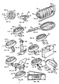
- FIGs 9-24 there is illustrated the identification marker of the present invention used in a variety of applications for identifying individual items in comparison with the means for identifying the ownership of golf clubs as above discussed with reference to Figures 1-8.
- the various embodiments of the identification markers shown in Figures 9-24 have elements identified by like numerals for the identification marker 10 shown in Figures 1-4, where like parts shown in Figures 1-4 are identified by like numerals in Figures 9-24.
- an identification marker 88 having the disc-body 16 with the cyclindrical anchor member 18 which includes in this embodiment the conical head 20 formed on the end of the anchor member 18.
- the conical head 20 has an annular shoulder 22.
- the identification marker 88 includes the protective collar 30 around the periphery of the body 16 with identification indicia 32, such as name and telephone number, engraved on the top of the marker 88 within the area protected by the collar 30.
- identification indicia includes at least a telephone number of the owner of the item to which the marker 88 is attached.
- the identification marker is inserted within the the hole (not shown) provided in the end of a grip 90 attached to the handlebars 92 of a bicycle or motorcycle. In this manner the owner of the bicycle is identified by the name and telephone number appearing on the identification marker 88.
- identification marker 94 shown in Figure 13 is attached to the handle portion 96 of a tennis racket 98.
- the marker 94 shown in Figure 13 includes an anchor member 100 having a tapered end portion 102 that terminates in a point 104. With the point 104 marker 94 may be engaged into the material forming the tennis racket handle 96 as shown in Figure 14. Thus, the marker 94 serves to identify the owner of the tennis racket 98.
- FIG. 15 A similar approach to identifying an item of personal possession is shown in Figures 15 and 16 where identification marker 106 is secured to end 108 of hammer 110.
- the marker 106 includes an anchor member 112 having threads 114 thereon. In this manner the marker 106 can be threadedly engaged to the hammer handle 108.
- the marker 106 includes a annular protective collar 116 which is discontinuous at diametrically opposed portions in a manner similar to that shown for the marker in Figure 5. The discontinuity in the collar 116 facilitates the necessary threading of the anchor member 112 into the end of the hammer handle 108.
- the identification marker 118 shown in Figure 17 is provided with a "tie clasp" type anchor member 120 having a closure member 122 releasably engageable with the tapered pin end portion 124.
- a "tie clasp" type anchor member 120 having a closure member 122 releasably engageable with the tapered pin end portion 124.
- the pin as shown in Figure 18 is inserted through the flap 126 of a briefcase 128.
- the pin is securely held in place by repositioning of the closure member 122 on the pin 124 in a conventional manner.
- the identification marker 118 is securely attached to the briefcase 128.
- identification marker 130 having a corkscrew shaped anchor member 132 to facilitate connection of the marker 130 to the back 134 of a chair 136.
- identification marker 138 includes a bifurcated pin anchor member 140 having portions 142 and 144 that when in close adjacency are passed through an opening, such as an opening 146 in a camera case 148 shown in Figure 22. After the anchor member portions 142 and 144 are extended through the opening 146 they are spread apart to securely connect the identification marker 138 to the camera case 148.
- the shaft-like anchor member is deleted and the connection of the marker 150 to an object, such as a portable radio 152, is accomplished by adhesively securing the disc-like body portion 16 to the portable radio. Removal of the marker 150 from the radio requires breaking the adhesive bond. This is not easily accomplished and requires prying the marker from the case of the radio, leaving an undesireable mark on the radio case. This has a deterring effect on theft of the item.
- FIGS 9-24 illustrate a wide variety of means by which the identification marker can be secured to a personal item
- the present invention is not limited to the specific anchor means discussed above.
- Numerous alternatives for anchor means can be utilized to not only releasably secure the identification marker to an object but also to permanently secure the marker to an object in such a manner that damage to the personal item would be required to successfully remove the marker. In this manner the identification marker serves as a means to deter theft of the personal item.
Landscapes
- Health & Medical Sciences (AREA)
- General Health & Medical Sciences (AREA)
- Physical Education & Sports Medicine (AREA)
- Engineering & Computer Science (AREA)
- General Engineering & Computer Science (AREA)
- Physics & Mathematics (AREA)
- General Physics & Mathematics (AREA)
- Theoretical Computer Science (AREA)
- Mechanical Engineering (AREA)
- Golf Clubs (AREA)
- Adornments (AREA)
- Exchange Systems With Centralized Control (AREA)
- Materials For Medical Uses (AREA)
- Length Measuring Devices With Unspecified Measuring Means (AREA)
- Length Measuring Devices By Optical Means (AREA)
- Machine Tool Sensing Apparatuses (AREA)
- Dental Preparations (AREA)
- Gloves (AREA)
- Pyrane Compounds (AREA)
- Transition And Organic Metals Composition Catalysts For Addition Polymerization (AREA)
Priority Applications (1)
| Application Number | Priority Date | Filing Date | Title |
|---|---|---|---|
| AT88311547T ATE85896T1 (de) | 1987-12-07 | 1988-12-06 | Identifikationszeichner. |
Applications Claiming Priority (2)
| Application Number | Priority Date | Filing Date | Title |
|---|---|---|---|
| US07/129,718 US4822052A (en) | 1987-12-07 | 1987-12-07 | Golf club grip attachment for identification and ball position marking |
| US129718 | 1987-12-07 |
Publications (3)
| Publication Number | Publication Date |
|---|---|
| EP0320212A2 true EP0320212A2 (de) | 1989-06-14 |
| EP0320212A3 EP0320212A3 (en) | 1989-12-06 |
| EP0320212B1 EP0320212B1 (de) | 1993-02-24 |
Family
ID=22441264
Family Applications (1)
| Application Number | Title | Priority Date | Filing Date |
|---|---|---|---|
| EP88311547A Expired - Lifetime EP0320212B1 (de) | 1987-12-07 | 1988-12-06 | Identifikationszeichner |
Country Status (11)
| Country | Link |
|---|---|
| US (1) | US4822052A (de) |
| EP (1) | EP0320212B1 (de) |
| JP (1) | JP2825512B2 (de) |
| AT (1) | ATE85896T1 (de) |
| AU (1) | AU620057B2 (de) |
| BR (1) | BR8806441A (de) |
| CA (1) | CA1325106C (de) |
| DE (1) | DE3878664T2 (de) |
| ES (1) | ES2039042T3 (de) |
| IE (1) | IE63390B1 (de) |
| NZ (1) | NZ227244A (de) |
Cited By (5)
| Publication number | Priority date | Publication date | Assignee | Title |
|---|---|---|---|---|
| FR2668283A1 (fr) * | 1990-10-23 | 1992-04-24 | Bertrand Dominique | Plaque de reperage. |
| FR2679479A1 (fr) * | 1991-07-12 | 1993-01-29 | Mariethoz Jean Claude | Dispositif d'identification pour une piece d'outillage. |
| FR2766118A1 (fr) * | 1997-07-15 | 1999-01-22 | Leuvrey Edwige K L | Perfectionnements aux dispositifs de marquage a coeur des bois |
| EP1842428A1 (de) * | 2006-04-04 | 2007-10-10 | Seidic S.A. | Elektronischer und/oder visueller Kennzeichner zum Gewährleisten der Rückverfolgbarkeit in der Lebensmittelindustrie |
| EP2756419A4 (de) * | 2011-09-14 | 2015-07-01 | Skyhawke Technologies Llc | Gehäuse für telemetrie-, sensor-, verarbeitungs- und andere elektronische komponenten und fixierung eines solchen gehäuses an einem golfschläger |
Families Citing this family (50)
| Publication number | Priority date | Publication date | Assignee | Title |
|---|---|---|---|---|
| US4957293A (en) * | 1988-06-13 | 1990-09-18 | Byrd Danny L | Golf ball marker and holder apparatus for marker |
| US5106122A (en) * | 1991-03-21 | 1992-04-21 | Perelman Brad S | Combined calendar and catalog |
| US5282616A (en) * | 1993-01-13 | 1994-02-01 | Stacavich Notaro Marylou I | Golf ball marker |
| USD350178S (en) | 1993-06-25 | 1994-08-30 | Kristovich Edmin A | Golf ball marker |
| US5476258A (en) * | 1995-02-21 | 1995-12-19 | Frisone; Daniel | Golf ball position marker with slope indicator |
| USD375340S (en) | 1995-12-13 | 1996-11-05 | Strystar International, L.L.C. | Golf club grip |
| US5733208A (en) * | 1996-01-04 | 1998-03-31 | Fazekas; Craig A. | Multi-purpose golf tool and method |
| US5569103A (en) * | 1996-03-12 | 1996-10-29 | Sihn; Sang C. | Golf ball marker |
| US5759111A (en) * | 1996-12-13 | 1998-06-02 | Clark; William A. | Single tine divot repair tool |
| USD409705S (en) * | 1997-03-06 | 1999-05-11 | Fazekas Craig A | Multipurpose golf tool |
| US5853336A (en) * | 1997-03-27 | 1998-12-29 | Hufgard; John W. | Golfing aid |
| US5795249A (en) * | 1997-04-23 | 1998-08-18 | 4U2C, Inc. | Holder for golf ball marker |
| US6159107A (en) * | 1998-01-27 | 2000-12-12 | Billy D. Walton | Method and apparatus for golf club shaft support |
| USD406297S (en) * | 1998-01-28 | 1999-03-02 | Craig Fazekas | Golf tool |
| US6042484A (en) * | 1998-02-05 | 2000-03-28 | Streit; Kenneth F. | Golf club identification device |
| US6048274A (en) * | 1998-07-24 | 2000-04-11 | Lesage; James Grant Christopher | Apparatus for performing golf-related tasks |
| USD419631S (en) * | 1998-11-09 | 2000-01-25 | Craig Fazekas | Multipurpose golf tool |
| JP3826313B2 (ja) * | 2000-12-27 | 2006-09-27 | 幸士 岡本 | グリップエンド底部加重用錘及びグリップエンド底部加重構造 |
| US6758762B2 (en) | 2001-12-05 | 2004-07-06 | Carl Casey Markwood | Golf club grip in combination with ball marker and divot repairer |
| RU2214935C1 (ru) * | 2002-02-19 | 2003-10-27 | Ведерников Владимир Николаевич | Идентификатор шинного колеса и комплект таких идентификаторов |
| US6607076B1 (en) * | 2002-04-15 | 2003-08-19 | Benny E. Smith | Golf bag with club separator |
| JP2004097612A (ja) * | 2002-09-11 | 2004-04-02 | Toshitaka Namiki | スイングコントロールウエイト |
| US20050037873A1 (en) * | 2003-01-17 | 2005-02-17 | Ken Kennedy | Golf divot tool bearing a ball marker |
| CA2416579A1 (en) * | 2003-01-17 | 2004-07-17 | Ken Kennedy | Golf divot tool bearing a magnetic ball marker |
| US20040159028A1 (en) * | 2003-02-13 | 2004-08-19 | Jose Luis Muguerza | Information engraved on metalic tags adhered to the external surfaces of shoes |
| US20040254025A1 (en) * | 2003-06-13 | 2004-12-16 | Arnold Frumin | Advertising and item identification apparatus and method |
| US6966851B1 (en) * | 2004-02-18 | 2005-11-22 | Karen Ann England | Hat with ball marker |
| KR200357285Y1 (ko) * | 2004-04-19 | 2004-07-27 | 이필희 | 먼지 솔 |
| US20070072693A1 (en) * | 2005-09-23 | 2007-03-29 | John Kallberg | Golf club graphics |
| US7371955B2 (en) * | 2006-02-22 | 2008-05-13 | Pearl Musical Instrument Co. | Drum tuning key |
| US7828670B1 (en) | 2007-03-13 | 2010-11-09 | Jack Schroader | Putter grip ball marker retention system |
| US20100203979A1 (en) * | 2009-02-06 | 2010-08-12 | Par 72 LLC | Device for securing a golf ball marker to a golf club |
| US8581727B1 (en) | 2009-11-10 | 2013-11-12 | Jesse Daniel Koenig | Misplaced golf club alert system |
| JP4507266B1 (ja) * | 2009-11-20 | 2010-07-21 | 央 軽部 | ウェイト付グリップ構造体及びゴルフクラブ |
| USD632351S1 (en) * | 2010-01-29 | 2011-02-08 | John Scott | Golf ball marker and level |
| US20120024919A1 (en) * | 2010-07-30 | 2012-02-02 | Stephen Gilbert | Position Marker Holder |
| US9248353B1 (en) | 2010-11-10 | 2016-02-02 | Jesse Daniel Koenig | Golf club tracking system |
| US8888606B2 (en) * | 2011-05-26 | 2014-11-18 | Heavy Putter | Golf grip |
| US20130203517A1 (en) * | 2012-02-03 | 2013-08-08 | Cobra Golf Incorporated | Golf club grip with housing |
| US8517850B1 (en) | 2012-12-11 | 2013-08-27 | Cobra Golf Incorporated | Golf club grip with device housing |
| USD685870S1 (en) * | 2012-03-27 | 2013-07-09 | Perception Digital Limited | Exercise analyzer |
| US8905858B2 (en) * | 2012-08-06 | 2014-12-09 | Dunlop Sports Co., Ltd. | Club head with insert including securing member on outer surface |
| US9345939B2 (en) * | 2014-02-15 | 2016-05-24 | Jesse Fratkin | Golf club cover |
| US9676094B1 (en) | 2016-02-09 | 2017-06-13 | Eaton Corporation | Flexible implement grip |
| US10315083B1 (en) * | 2017-11-08 | 2019-06-11 | Cobra Golf Incorporated | Golf club grip |
| USD849166S1 (en) | 2017-12-07 | 2019-05-21 | Ssg International, Llc | Golf putter grip |
| US10099101B1 (en) | 2017-12-07 | 2018-10-16 | Ssg International, Llc | Golf club grip with sensor housing |
| EP4242423B1 (de) * | 2018-08-23 | 2025-04-23 | Sandvik Mining and Construction Australia (Production/Supply) Pty Ltd | Felsanker mit informationsanzeigeregion |
| USD929522S1 (en) * | 2019-10-31 | 2021-08-31 | Acushnet Company | Weight for a golf club grip |
| US20230044669A1 (en) * | 2021-08-03 | 2023-02-09 | Tyler Katchmar | Magnetic Golf Tee and Grip |
Family Cites Families (15)
| Publication number | Priority date | Publication date | Assignee | Title |
|---|---|---|---|---|
| US1840003A (en) * | 1931-06-16 | 1932-01-05 | Rolf T Warden | Identification umbrella handle |
| US1830936A (en) * | 1931-07-02 | 1931-11-10 | Faith Stephen | Initial or monogram cap for golf club shafts |
| US1974682A (en) * | 1934-05-05 | 1934-09-25 | Lancaster Pipe Mount Co | Identifying marker |
| US2083872A (en) * | 1936-11-04 | 1937-06-15 | Milton H Siegel | Umbrella handle or the like and identification means therefor |
| US2261959A (en) * | 1940-01-11 | 1941-11-11 | John W Buttikofer | Golf club and attachment therefor |
| US2700547A (en) * | 1952-07-02 | 1955-01-25 | Tricon Inc | Spot marker holder for golf clubs |
| US2979335A (en) * | 1960-07-25 | 1961-04-11 | Mark W Pruitt | Combination golf club and magnetically held marker |
| GB1043683A (en) * | 1963-08-27 | 1966-09-21 | Thomas Arthur Ltd | Holder for a golf marker |
| US3684294A (en) * | 1970-06-03 | 1972-08-15 | Robert S Champion | Golf club including stance diagram |
| US3749408A (en) * | 1971-09-13 | 1973-07-31 | S Mills | Golf putter |
| US3779551A (en) * | 1971-12-10 | 1973-12-18 | Aluminum Co Of America | Indicator element for ball bat |
| US3977674A (en) * | 1974-12-11 | 1976-08-31 | Zeller Henry O | Holder for a golf ball marking plate |
| US4168067A (en) * | 1977-11-21 | 1979-09-18 | Max Wiczer | Post for pinball game apparatus |
| US4195837A (en) * | 1978-08-11 | 1980-04-01 | Tacki-Mac Grips, Inc. | Golf club grip |
| US4380337A (en) * | 1981-11-20 | 1983-04-19 | Dimatteo Rocco J | Golf ball position marking device |
-
1987
- 1987-12-07 US US07/129,718 patent/US4822052A/en not_active Expired - Lifetime
-
1988
- 1988-12-06 EP EP88311547A patent/EP0320212B1/de not_active Expired - Lifetime
- 1988-12-06 AT AT88311547T patent/ATE85896T1/de not_active IP Right Cessation
- 1988-12-06 DE DE8888311547T patent/DE3878664T2/de not_active Expired - Fee Related
- 1988-12-06 ES ES198888311547T patent/ES2039042T3/es not_active Expired - Lifetime
- 1988-12-07 BR BR888806441A patent/BR8806441A/pt unknown
- 1988-12-07 JP JP63307960A patent/JP2825512B2/ja not_active Expired - Fee Related
- 1988-12-07 IE IE364988A patent/IE63390B1/en not_active IP Right Cessation
- 1988-12-07 CA CA000585240A patent/CA1325106C/en not_active Expired - Fee Related
- 1988-12-07 AU AU26632/88A patent/AU620057B2/en not_active Ceased
- 1988-12-07 NZ NZ227244A patent/NZ227244A/xx unknown
Cited By (5)
| Publication number | Priority date | Publication date | Assignee | Title |
|---|---|---|---|---|
| FR2668283A1 (fr) * | 1990-10-23 | 1992-04-24 | Bertrand Dominique | Plaque de reperage. |
| FR2679479A1 (fr) * | 1991-07-12 | 1993-01-29 | Mariethoz Jean Claude | Dispositif d'identification pour une piece d'outillage. |
| FR2766118A1 (fr) * | 1997-07-15 | 1999-01-22 | Leuvrey Edwige K L | Perfectionnements aux dispositifs de marquage a coeur des bois |
| EP1842428A1 (de) * | 2006-04-04 | 2007-10-10 | Seidic S.A. | Elektronischer und/oder visueller Kennzeichner zum Gewährleisten der Rückverfolgbarkeit in der Lebensmittelindustrie |
| EP2756419A4 (de) * | 2011-09-14 | 2015-07-01 | Skyhawke Technologies Llc | Gehäuse für telemetrie-, sensor-, verarbeitungs- und andere elektronische komponenten und fixierung eines solchen gehäuses an einem golfschläger |
Also Published As
| Publication number | Publication date |
|---|---|
| NZ227244A (en) | 1991-09-25 |
| CA1325106C (en) | 1993-12-14 |
| JPH01280786A (ja) | 1989-11-10 |
| EP0320212A3 (en) | 1989-12-06 |
| AU2663288A (en) | 1989-06-08 |
| AU620057B2 (en) | 1992-02-13 |
| IE63390B1 (en) | 1995-04-19 |
| DE3878664T2 (de) | 1993-06-09 |
| EP0320212B1 (de) | 1993-02-24 |
| ES2039042T3 (es) | 1993-08-16 |
| DE3878664D1 (de) | 1993-04-01 |
| JP2825512B2 (ja) | 1998-11-18 |
| ATE85896T1 (de) | 1993-03-15 |
| BR8806441A (pt) | 1989-08-22 |
| US4822052A (en) | 1989-04-18 |
Similar Documents
| Publication | Publication Date | Title |
|---|---|---|
| EP0320212B1 (de) | Identifikationszeichner | |
| US5282616A (en) | Golf ball marker | |
| US4380337A (en) | Golf ball position marking device | |
| US5372362A (en) | Golf accessory device | |
| US4858925A (en) | Golf club combined with ball position marker | |
| US3136547A (en) | Ball position marker | |
| US5082231A (en) | Post holder and marker therefor | |
| US5417426A (en) | Putt mark putter | |
| US5898946A (en) | Golf hat and ball marker assembly | |
| US6422955B1 (en) | Magnetic golf ball marker and holder | |
| US4838416A (en) | Golf club holster | |
| US6457184B1 (en) | Hat with golf ball marking device | |
| US5025843A (en) | Golf club head cover keeper | |
| US6379271B1 (en) | Golf accessory | |
| WO2013177033A1 (en) | Magnetically attached golf tee | |
| US5351949A (en) | Putter-mounted holder for golf ball position marker | |
| US6200226B1 (en) | Golf putter | |
| US5795249A (en) | Holder for golf ball marker | |
| US20170239539A1 (en) | Golf divot repair and ball marker device with putter cover retention | |
| US6729536B2 (en) | Combination golf ball marker and stroke indicator device | |
| US6564391B2 (en) | Headgear with ball marker | |
| US6599205B1 (en) | Combination ball marker and turf repair golf tool promotional device | |
| US7559858B2 (en) | Apparatus and method for indicating a golf ball's position on the field of play | |
| US20070117657A1 (en) | Golf accessory | |
| JP2000107337A (ja) | ゴルフクラブ用表示具 |
Legal Events
| Date | Code | Title | Description |
|---|---|---|---|
| PUAI | Public reference made under article 153(3) epc to a published international application that has entered the european phase |
Free format text: ORIGINAL CODE: 0009012 |
|
| AK | Designated contracting states |
Kind code of ref document: A2 Designated state(s): AT BE CH DE ES FR GB IT LI LU NL SE |
|
| PUAL | Search report despatched |
Free format text: ORIGINAL CODE: 0009013 |
|
| AK | Designated contracting states |
Kind code of ref document: A3 Designated state(s): AT BE CH DE ES FR GB IT LI LU NL SE |
|
| 17P | Request for examination filed |
Effective date: 19900517 |
|
| 17Q | First examination report despatched |
Effective date: 19910207 |
|
| GRAA | (expected) grant |
Free format text: ORIGINAL CODE: 0009210 |
|
| AK | Designated contracting states |
Kind code of ref document: B1 Designated state(s): AT BE CH DE ES FR GB IT LI LU NL SE |
|
| PG25 | Lapsed in a contracting state [announced via postgrant information from national office to epo] |
Ref country code: IT Free format text: LAPSE BECAUSE OF FAILURE TO SUBMIT A TRANSLATION OF THE DESCRIPTION OR TO PAY THE FEE WITHIN THE PRE;WARNING: LAPSES OF ITALIAN PATENTS WITH EFFECTIVE DATE BEFORE 2007 MAY HAVE OCCURRED AT ANY TIME BEFORE 2007. THE CORRECT EFFECTIVE DATE MAY BE DIFFERENT FROM THE ONE RECORDED.SCRIBED TIME-LIMIT Effective date: 19930224 Ref country code: AT Effective date: 19930224 Ref country code: CH Effective date: 19930224 Ref country code: FR Effective date: 19930224 Ref country code: LI Effective date: 19930224 Ref country code: NL Effective date: 19930224 Ref country code: BE Effective date: 19930224 |
|
| REF | Corresponds to: |
Ref document number: 85896 Country of ref document: AT Date of ref document: 19930315 Kind code of ref document: T |
|
| REF | Corresponds to: |
Ref document number: 3878664 Country of ref document: DE Date of ref document: 19930401 |
|
| REG | Reference to a national code |
Ref country code: CH Ref legal event code: PL |
|
| EN | Fr: translation not filed | ||
| NLV1 | Nl: lapsed or annulled due to failure to fulfill the requirements of art. 29p and 29m of the patents act | ||
| REG | Reference to a national code |
Ref country code: ES Ref legal event code: FG2A Ref document number: 2039042 Country of ref document: ES Kind code of ref document: T3 |
|
| PLBE | No opposition filed within time limit |
Free format text: ORIGINAL CODE: 0009261 |
|
| STAA | Information on the status of an ep patent application or granted ep patent |
Free format text: STATUS: NO OPPOSITION FILED WITHIN TIME LIMIT |
|
| PG25 | Lapsed in a contracting state [announced via postgrant information from national office to epo] |
Ref country code: LU Free format text: LAPSE BECAUSE OF NON-PAYMENT OF DUE FEES Effective date: 19931231 |
|
| 26N | No opposition filed | ||
| EAL | Se: european patent in force in sweden |
Ref document number: 88311547.9 |
|
| REG | Reference to a national code |
Ref country code: GB Ref legal event code: IF02 |
|
| PGFP | Annual fee paid to national office [announced via postgrant information from national office to epo] |
Ref country code: GB Payment date: 20041206 Year of fee payment: 17 |
|
| PGFP | Annual fee paid to national office [announced via postgrant information from national office to epo] |
Ref country code: ES Payment date: 20041209 Year of fee payment: 17 |
|
| PGFP | Annual fee paid to national office [announced via postgrant information from national office to epo] |
Ref country code: DE Payment date: 20041216 Year of fee payment: 17 |
|
| PGFP | Annual fee paid to national office [announced via postgrant information from national office to epo] |
Ref country code: SE Payment date: 20041217 Year of fee payment: 17 |
|
| PG25 | Lapsed in a contracting state [announced via postgrant information from national office to epo] |
Ref country code: GB Free format text: LAPSE BECAUSE OF NON-PAYMENT OF DUE FEES Effective date: 20051206 |
|
| PG25 | Lapsed in a contracting state [announced via postgrant information from national office to epo] |
Ref country code: SE Free format text: LAPSE BECAUSE OF NON-PAYMENT OF DUE FEES Effective date: 20051207 Ref country code: ES Free format text: LAPSE BECAUSE OF NON-PAYMENT OF DUE FEES Effective date: 20051207 |
|
| PG25 | Lapsed in a contracting state [announced via postgrant information from national office to epo] |
Ref country code: DE Free format text: LAPSE BECAUSE OF NON-PAYMENT OF DUE FEES Effective date: 20060701 |
|
| EUG | Se: european patent has lapsed | ||
| GBPC | Gb: european patent ceased through non-payment of renewal fee |
Effective date: 20051206 |
|
| REG | Reference to a national code |
Ref country code: ES Ref legal event code: FD2A Effective date: 20051207 |