EP0320252B1 - Machines électriques tournantes - Google Patents
Machines électriques tournantes Download PDFInfo
- Publication number
- EP0320252B1 EP0320252B1 EP88311615A EP88311615A EP0320252B1 EP 0320252 B1 EP0320252 B1 EP 0320252B1 EP 88311615 A EP88311615 A EP 88311615A EP 88311615 A EP88311615 A EP 88311615A EP 0320252 B1 EP0320252 B1 EP 0320252B1
- Authority
- EP
- European Patent Office
- Prior art keywords
- core
- machine according
- stator
- laminations
- support structure
- Prior art date
- Legal status (The legal status is an assumption and is not a legal conclusion. Google has not performed a legal analysis and makes no representation as to the accuracy of the status listed.)
- Expired - Lifetime
Links
- 238000004804 winding Methods 0.000 claims description 33
- 238000003475 lamination Methods 0.000 claims description 32
- 235000015895 biscuits Nutrition 0.000 claims description 9
- 230000006835 compression Effects 0.000 claims description 3
- 238000007906 compression Methods 0.000 claims description 3
- 239000004020 conductor Substances 0.000 claims description 2
- 230000000452 restraining effect Effects 0.000 claims 1
- 238000010276 construction Methods 0.000 description 5
- 239000002783 friction material Substances 0.000 description 5
- 238000004873 anchoring Methods 0.000 description 3
- 239000002826 coolant Substances 0.000 description 3
- 238000013016 damping Methods 0.000 description 2
- 239000012530 fluid Substances 0.000 description 2
- 239000000463 material Substances 0.000 description 2
- RYGMFSIKBFXOCR-UHFFFAOYSA-N Copper Chemical compound [Cu] RYGMFSIKBFXOCR-UHFFFAOYSA-N 0.000 description 1
- 229910000831 Steel Inorganic materials 0.000 description 1
- 230000015572 biosynthetic process Effects 0.000 description 1
- 229910052802 copper Inorganic materials 0.000 description 1
- 239000010949 copper Substances 0.000 description 1
- 238000006073 displacement reaction Methods 0.000 description 1
- 230000000694 effects Effects 0.000 description 1
- 230000005284 excitation Effects 0.000 description 1
- 238000003780 insertion Methods 0.000 description 1
- 230000037431 insertion Effects 0.000 description 1
- 238000009434 installation Methods 0.000 description 1
- 238000004519 manufacturing process Methods 0.000 description 1
- 239000000203 mixture Substances 0.000 description 1
- 230000002093 peripheral effect Effects 0.000 description 1
- -1 polytetrafluoroethylene Polymers 0.000 description 1
- 229920001343 polytetrafluoroethylene Polymers 0.000 description 1
- 239000004810 polytetrafluoroethylene Substances 0.000 description 1
- 230000000284 resting effect Effects 0.000 description 1
- 239000010959 steel Substances 0.000 description 1
- 238000003466 welding Methods 0.000 description 1
Images

Classifications
-
- H—ELECTRICITY
- H02—GENERATION; CONVERSION OR DISTRIBUTION OF ELECTRIC POWER
- H02K—DYNAMO-ELECTRIC MACHINES
- H02K1/00—Details of the magnetic circuit
- H02K1/06—Details of the magnetic circuit characterised by the shape, form or construction
- H02K1/12—Stationary parts of the magnetic circuit
- H02K1/18—Means for mounting or fastening magnetic stationary parts on to, or to, the stator structures
- H02K1/185—Means for mounting or fastening magnetic stationary parts on to, or to, the stator structures to outer stators
-
- H—ELECTRICITY
- H02—GENERATION; CONVERSION OR DISTRIBUTION OF ELECTRIC POWER
- H02K—DYNAMO-ELECTRIC MACHINES
- H02K15/00—Processes or apparatus specially adapted for manufacturing, assembling, maintaining or repairing of dynamo-electric machines
- H02K15/02—Processes or apparatus specially adapted for manufacturing, assembling, maintaining or repairing of dynamo-electric machines of stator or rotor bodies
- H02K15/028—Fastening stator or rotor bodies to casings, supports, shafts or hubs
-
- H—ELECTRICITY
- H02—GENERATION; CONVERSION OR DISTRIBUTION OF ELECTRIC POWER
- H02K—DYNAMO-ELECTRIC MACHINES
- H02K3/00—Details of windings
- H02K3/46—Fastening of windings on the stator or rotor structure
- H02K3/50—Fastening of winding heads, equalising connectors, or connections thereto
- H02K3/505—Fastening of winding heads, equalising connectors, or connections thereto for large machine windings, e.g. bar windings
-
- Y—GENERAL TAGGING OF NEW TECHNOLOGICAL DEVELOPMENTS; GENERAL TAGGING OF CROSS-SECTIONAL TECHNOLOGIES SPANNING OVER SEVERAL SECTIONS OF THE IPC; TECHNICAL SUBJECTS COVERED BY FORMER USPC CROSS-REFERENCE ART COLLECTIONS [XRACs] AND DIGESTS
- Y10—TECHNICAL SUBJECTS COVERED BY FORMER USPC
- Y10T—TECHNICAL SUBJECTS COVERED BY FORMER US CLASSIFICATION
- Y10T29/00—Metal working
- Y10T29/49—Method of mechanical manufacture
- Y10T29/49002—Electrical device making
- Y10T29/49009—Dynamoelectric machine
Definitions
- This invention relates to large rotary electrical machines, eg. with ratings of 1MW and upwards, having a generally horizontal axis of rotation.
- rotary electrical machines for example generators of turbine-generator sets
- a stator construction comprising a generally annular outer casing which carries the stator core and the stator winding either directly or through an inner annular core frame (see "The Mechanical Design of Large Turbogenerators, B.A Marlow, Proc. Instn. Mech. Engrs., Vol. 200 (1986) No. 135).
- outer casing or the core frame has struts extending radially inwards that provide support and location for the core laminations.
- Heavy end plates sometimes secured together by through bolts, hold the laminations together under a relatively high compressive force in order to limit axial thermal expansion and vibration.
- the outer casing or the core frame is first constructed and is fitted with one end plate. It is then stood with its axis vertical and the end plate lowermost so that the laminations, usually in segmental form, can be dropped individually into the frame and fitted into place. The other end plate can then be added and the core laminations clamped, after which the core frame is returned to a horizontal position for the remaining assembly operations, including fitting the windings.
- the construction of the core frame and fitting the core laminations into it which typically can take 16-20 weeks for a 500MW generator, adds significantly to the costs of manufacture as well as requiring significant capital investment for plant capable of handling the core frame during the various operations.
- a rotary electrical machine comprising an open topped support structure containing a stator having an annular core comprising laminations held under compression between end plates and mounted on supports within said structure, a rotor extending through the core and mounted for rotation about a horizontal axis, the interior of said structure being accessible from above wherein the open top of said support structure is provided for the assembly of the core, said supports of the structure extending along the length of the core laminations to engage with downwardly directed faces of the core laminations on opposite sides of a vertical plane through said axis, whereby the stator core can be assembled on the support structure by lowering the laminations and/or biscuits thereof onto said supports with the structure horizontal.
- the assembly space can be arranged to be accessible both from the sides and from above, simplifying the task of bringing the laminations into position.
- the stator supports are conveniently disposed below the axis of rotation to cooperate with downwardly directed faces of the stator core that are part of a regular polygonal or circular cross-section of the core.
- the support structure of the present invention allows the core to be mounted in a manner that avoids this problem, by arranging that the core is axially engaged with the support structure at a location along its length and is otherwise free to move axially relative thereto, whereby relative thermal movement between the core and the structure can occur relatively freely.
- FIG. 1 illustrates a generator 10 having a support structure 12, an annular stator core 14 supported on the structure, a rotor 16 extending through the core and mounted on bearings (not shown) for rotation about a end winding supports on the ends of the tension elements and the second group of clamping elements securing the core laminations between and spaced from said end winding supports, said second group applying said axial clamping pressure to the core laminations, and spring means being provided on the tension elements to permit relative axial movement between said first and second groups of clamping elements at least at one end of the stator.
- This arrangement for permitting thermal movements between the windings and the core in the axial direction can also be employed in otherwise conventional rotary electrical machines, ie. independently of whether there is provision for relative thermal movement between the core and its support structure.
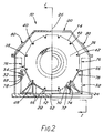
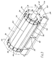
- FIG. 1 illustrates a generator 10 having a support structure 12, an annular stator core 14 supported on the structure, a rotor 16 extending through the core and mounted on bearings (not shown) for rotation about a horizontal axis 18, and a fluid-tight housing 20 encasing the stator and rotor.
- the support structure 12 comprises a base member 22 upon which there are fixed upstands in the form of two support beams 24, one located on each side of the central axial plane 26 of the generator and running parallel to the rotary axis to extend along the full length of the core 14.
- the core has a regular polygonal cross-section and rests through two downwardly directed faces of that cross-section on top webs 28 of the beams 24 and is separated from them by low-friction material 30, such as polytetrafluoroethylene.
- Two axially spaced core support cradles 32 are also mounted on the base member 22.
- the cradles 32 each have a profile facing the core 14 which is shaped to conform generally to the opposed peripheral region of the core 14, but preferably there is normally a small clearance between them and the core.
- the core 14 comprises two end plates 34,36 between which are clamped a plurality of biscuits 38 (not shown individually) of pre-assembled core laminations.
- the clamping pressure is applied by tie bolts 40 extending axially through recesses 42 in the periphery of the laminated body of the core and apertures in the end plates, nuts 44 being threaded on the bolts at both ends of the core.
- Springs 46 are mounted between the nuts and one end plate 36 to accommodate differential thermal movement between the bolts and the laminated core axially of the core. Restraint of this relative movement is minimised by ensuring that there are adequate radial clearances for the bolts and by using low friction material where required on sliding surfaces.
- the tie bolts 40 extend beyond both ends of the stator core, their terminal portions being employed to mount frusto-conical end winding supports 54,56 which are secured at a spacing from the end plates 34,36 by further nuts 44 on the ends of the bolts 40.
- the stator windings 58 held in slots in the core, extend from the ends of the core and their end windings are secured on the supports 54,56 by clamps 60.
- the materials of the windings 58 and of the bolts 40 can be so chosen that it is not necessary to design for relative thermal movement between them.
- windings of copper have a coefficient of expansion of 17x10 ⁇ 6 /°C, with which can be employed bolts of austenitic steel which has a coefficient of 18x10 ⁇ 6/°C.
- Both end plates 34,36 of the core have lower extensions 34a,36a respectively, that are a free sliding fit between the beams 24.
- the sides of the extensions are preferably vertical or taper downwardly so that the end plates can be lowered into place.
- One end plate 34 of the core is axially fixed on the support structure 12.
- the end plate has an integral key formation 62 which engages a slot 64 in the base member 22.
- the end plate is firmly anchored to the beams 24, for example by bolted brackets (not shown) or welding.
- the remainder of the core is free to expand and contract axially on the beams 24 under the influence of thermal effects.
- the low-friction material 30 is preferably fixed to the core face so that it slides with the core, thereby preventing damage to the edges of the laminations. Such movement relative to the tie bolts is possible because of the provision of the springs 46. Relative axial movement is also possible between the stator windings and the core, the windings being located by the end winding supports substantially independently of axial movements of the core itself. It is preferably at the end winding support 54, adjacent the fixed end plate 34, that the stator end windings extend to connectors (not shown) for connection to external conductors (not shown) in known manner. With these measures, although biscuits are used to build up the core, with a consequent high thermal expansion rate of the main body of the core, the axial forces imposed on the windings remain minimal.
- the mass of the stator core may be sufficient to allow it to rest stably on the supporting slides, uninfluenced by torques arising from the electromagnetic forces imposed during operation. Similarly lifting of the free end of the core, remote from the end plate is resisted by the core mass.
- the polygonal cross-section of the core and the conforming profile of the support structure facing it, in particular the cradles 32, can of course resist any tendency of the core to turn on its axis. Local resistance against rotation and lifting can be offered by the extensions 34a,36a of the end plates.
- keying means which give a positive restraint along the length of the core against such displacements.
- axial keys 66 which extend between keyways 68 in the cradles 32 and the adjoining recesses 42 in the biscuits, these recesses extending into the end plates 34,36.
- the axially displaceable end plate 36 has a pair of wedge-shaped keyways 72 which engage dovetail key blocks 74 secured to the facing side surfaces of the beams 24 so that the end plate 36 serves to guide the axial movements of the core.
- the outer peripheries of the end winding supports 54,56 can also engage the beams 24 slidably, and possibly be supported by the beams. This, and also the mounting of the end winding supports at a spacing from the stator core helps to isolate the windings 58 from axial movements of the core 14 and assisting in the control of vibration.
- the support 54 can additionally or alternatively be in contact with the end plate 34.
- the stator can be assembled on the support structure 12 by lowering the end plates 34,36 and the core biscuits 38 into position on the horizontal support beams 24, this being facilitated by the fact that there is open access on both sides of the structure 12 as well as from above, and the assembled elements of the core are clamped together by the tie bolts 40. It is also possible to assemble individual annular laminations on the support structure to build up the core, although that would take longer.
- the stator winding end rings 54,56 can then be secured on the ends of the through bolts, the windings 58 inserted in their slots in the assembled core, and the ends of the windings secured to the end rings and electrically coupled to the core windings.
- coolant circulation means may be put in place before or after the building of the core, as convenient.
- the core laminations will of course have further aligned slots, holes etc., in the conventional manner, for such purposes as the flow of coolant fluid.
- Coolers for the circulating coolant fluid can be located in any convenient place, for example, within the housing alongside the core and between the cradles, and between the central cradle 32 and the end plate 34 as shown in ghost outline at 76 in Fig. 2.
- insertions (not shown) of rubber or other suitable damping material can be put at appropriate locations, eg. between the core and the low friction material 30 and also between the fixed end plate 34 and the main body of the stator core.
- anti-vibration devices known per se, can be connected between the core and the base member 22. It may be preferred, in order to isolate the housing and rotor bearings as far as possible from the stator vibrations, to mount the housing 20 and the rotor bearings directly onto the foundations (not shown) on which the base member 22 will rest.
- the housing 20 is mounted on the base member 22 together with the rotor bearings (not shown) that lie beyond the ends of the stator. Consequently, it is possible to move the generator as a self-contained unit.
- the cradles 32 have attachment points 78 for a lift harness, the points 78 being accessible via housing apertures normally closed by plates 80. It will be appreciated that the generator, when suspended from these points, derives considerable stiffness from the assembled core; this illustrates a further unique feature of the construction in that the core functions as a significant structural member.
- the illustrated construction can be modified in many ways within the scope of the invention.
- the tie bolts 40 are shown running in open slots in the periphery of the main body of the core, but they can be arranged on a pitch circle greater than the outside diameter of the core 14, the end rings 34,36 and the end winding supports 54,46 being furnished with apertured radial lugs to receive the bolts.
- the bolts can also be located on pitch circles of different diameters.
- the anchoring of the core 14 relative to the support structure 12 need not be at an end of the core. By anchoring the core elsewhere, eg. in the middle of its length, both ends can be left free to move axially.
- the anchoring of the core can be achieved in a number of ways.
- a key can engage respective keyways formed in the base member 22 and the outer periphery of the core laminations intermediate the length of the core, a third cradle 32 being provided to support the end of the core.
- a key can be formed integrally with the third cradle 32 adjacent that end of the core, the key engaging a keyway in the outer periphery of the core laminations.
- the support beams 24 are shown in Fig. 3 extending beyond the core, to support, for example, the generator exciter and the rotor bearings. However, it is also possible to dispense with the beams 24.
- the core is mounted on bearing blocks resting on slideways carried by the cradles 32, the slideways being lubricated or faced with low-friction material.
- the cradles 32 are fixed relative to the core and are themselves slidable in slideways.
- the core is mounted on relatively thin supports which can flex in the axial direction. Also, more closely analogous to the illustrated example, the core can be mounted on rollers to permit its axial expansion.
- the external cross-section shape of the core is not limited to the dodecahedron shown and may, for example, be circular.
Landscapes
- Engineering & Computer Science (AREA)
- Power Engineering (AREA)
- Manufacturing & Machinery (AREA)
- Iron Core Of Rotating Electric Machines (AREA)
- Insulation, Fastening Of Motor, Generator Windings (AREA)
- Motor Or Generator Frames (AREA)
Claims (14)
- Machine électrique tournante comprenant une structure de support présentant un dessus ouvert (12) contenant un stator possédant un noyau annulaire (14) comprenant des laminés maintenus sous compression entre des plaques d'extrémité (34,36) et montés sur des supports (24) à l'intérieur de ladite structure, à rotor (16) s'étendant à travers le noyau et monté à rotation autour d'un axe horizontal, l'intérieur de ladite structure étant accessible depuis le dessus, caractérisée en ce que le dessus ouvert de ladite structure de support (12) est prévu pour l'assemblage du noyau, lesdits supports (24) de la structure s'étendant suivant la longueur des laminés de noyau pour venir en prise avec des faces dirigées vers le bas des laminés de noyau sur des côtés opposés d'un plan vertical à travers ledit axe, par quoi le noyau de stator peut être assemblé sur la structure en abaissant les laminés et/ou biscuits de celle-ci sur lesdits supports, la structure étant en position horizontale.
- Machine selon la revendication 1, dans laquelle les plaques d'extrémité (34,36) sont pourvues d'éléments (34a, 36a, 72) qui coopèrent avec la structure de support pour résister à un couple et/ou des forces de soulèvement sur le noyau du stator.
- Machine selon la revendication 1 ou la revendication 2, dans laquelle le noyau (14) vient axialement en prise avec la structure de support (12) à une localisation suivant sa longueur et est sinon déplaçable axialement relativement à celle-ci, par quoi des mouvements thermiques relatifs peuvent se produire librement entre le noyau et la structure de support dans la direction axiale.
- Machine selon la revendication 3, dans laquelle ledit engagement axial est réalisé par la plaque d'extrémité (34) à une extrémité du noyau, au moyen d'une saillie à clavette (62) sur l'autre plaque d'extrémité venant en prise avec la structure de support.
- Machine selon la revendication 3 ou la revendication 4, dans laquelle au moins une clavette s'étendant axialement et une connexion de logement de clavette (66, 68; 72, 74) est prévue entre la structure de support (12) et le noyau de stator (14) pour une limitation de rotation et/ou de torsion du noyau sur ladite structure, ladite clavette et connexion de logement de clavette étant en prise coulissante pour permettre un mouvement axial relatif entre le noyau et ladite structure.
- Machine selon l'une des revendications précédentes, dans laquelle les enroulements du stator (58) sont montés dans le noyau (14) par des moyens permettant des mouvements thermiques relatifs entre les enroulements et le noyau dans la direction axiale.
- Machine selon l'une des revendications 3 à 5 conjointement avec la revendication 6, dans laquelle l'engagement axial est prévu à ou adjacent à une extrémité du noyau duquel les enroulements du noyau (58) s'étendent pour la connexion à des conducteurs électriques extérieurs.
- Machine selon l'une des revendications précédentes, dans laquelle la structure de support comprend des poutres respectives (24) sur des côtés opposés d'un plan vertical à travers l'axe rotatif agissant comme support de poids pour le noyau de stator (14) sur au moins une partie essentielle de la longueur du noyau, le noyau étant supporté de façon coulissante axialement sur lesdites poutres.
- Machine selon l'une des revendications précédentes, dans laquelle le noyau (14) a un profil non-circulaire en section transversale en prise avec des éléments (66) de la structure de support sur des côtés opposés du plan vertical à travers l'axe rotatif pour limiter les déviations de rotation et/ou de torsion du noyau autour d'un centre axial.
- Machine selon l'une des revendications précédentes, dans laquelle des éléments de tension (40) s'étendent axialement à travers le noyau (14) pour maintenir les laminés comprimés entre les plaques d'extrémité, et des moyens de ressort (46) sont prévus pour lesdits éléments de tension pour permettre des mouvements thermiques relatifs entre le noyau et les éléments de tension axialement par rapport à la machine.
- Machine selon la revendication 10, dans laquelle les éléments de tension (40) s'étendent au-delà des plaques d'extrémité de noyau (34, 36) pour constituer des montages pour des supports d'enroulement (54, 56) espacés des plaques d'extrémité.
- Machine selon la revendication 11, dans laquelle les supports d'enroulement (54, 56) se présentent sous la forme d'éléments sensiblement tronconiques concentnques avec le noyau, leurs extrémités de plus petit diamètre faisant saillie vers mais étant espacés des plaques d'extrémité de noyau (34, 36).
- Machine selon l'une des revendications 10 à 12, dans laquelle des fentes (42) s'ouvrant sur la périphérie extérieure du noyau réalisent des localisations pour des éléments de tension (40), par quoi lesdits éléments peuvent être insérés de l'extérieur transversalement à l'axe de rotation.
- Machine selon l'une des revendications 1 à 9, dans laquelle le noyau (14) supporte des enroulements de stator (58) qui s'étendent axialement depuis les deux extrémités du noyau où ils sont retenus par des supports des extrémités d'enroulement (54, 56) qui sont montés sur les éléments de tension (40) s'étendant sur la longueur du stator, lesdits éléments (40) supportant des premier et deuxième groupes d'éléments de serrage (44), le premier groupe d'éléments de serrage fixant les supports des extrémités d'enroulement sur les extrémités des éléments de tension, et le deuxième groupe d'éléments de serrage fixant les laminés de noyau entre et espacés desdits supports des extrémités d'enroulement, ledit deuxième groupe appliquant ladite pression de serrage axiale aux laminés de noyau, et les moyens de ressort (46) sont prévus sur les éléments de tension pour permettre un mouvement axial relatif entre lesdits premier et deuxième groupes d'éléments de serrage au moins à une extrémité du stator.
Priority Applications (1)
| Application Number | Priority Date | Filing Date | Title |
|---|---|---|---|
| AT88311615T ATE100979T1 (de) | 1987-12-11 | 1988-12-08 | Rotierende elektrische maschinen. |
Applications Claiming Priority (4)
| Application Number | Priority Date | Filing Date | Title |
|---|---|---|---|
| GB878729045A GB8729045D0 (en) | 1987-12-11 | 1987-12-11 | Rotary electrical machines |
| GB888820485A GB8820485D0 (en) | 1987-12-11 | 1988-08-30 | Frameless stator core |
| GB8820485 | 1988-08-30 | ||
| GB8729045 | 1988-08-30 |
Publications (3)
| Publication Number | Publication Date |
|---|---|
| EP0320252A2 EP0320252A2 (fr) | 1989-06-14 |
| EP0320252A3 EP0320252A3 (en) | 1990-12-05 |
| EP0320252B1 true EP0320252B1 (fr) | 1994-01-26 |
Family
ID=26293193
Family Applications (1)
| Application Number | Title | Priority Date | Filing Date |
|---|---|---|---|
| EP88311615A Expired - Lifetime EP0320252B1 (fr) | 1987-12-11 | 1988-12-08 | Machines électriques tournantes |
Country Status (5)
| Country | Link |
|---|---|
| US (1) | US4894573A (fr) |
| EP (1) | EP0320252B1 (fr) |
| JP (1) | JP2739111B2 (fr) |
| DE (1) | DE3887481T2 (fr) |
| ES (1) | ES2051866T3 (fr) |
Families Citing this family (27)
| Publication number | Priority date | Publication date | Assignee | Title |
|---|---|---|---|---|
| US5185547A (en) * | 1992-01-31 | 1993-02-09 | Westinghouse Electric Corp. | Dynamo-electric machine stator core construction |
| US5300846A (en) * | 1992-10-08 | 1994-04-05 | Otis Elevator Company | Lamination support for a linear motor |
| US5744885A (en) * | 1994-12-16 | 1998-04-28 | General Electric Co. | Modular generator frame construction |
| DE19517524A1 (de) * | 1995-05-12 | 1996-11-14 | Abb Management Ag | Horizontalachsige elektrische Maschine |
| US5783892A (en) * | 1995-06-26 | 1998-07-21 | Kabushiki Kaisha Toshiba | Stator for dynamoelectric machines |
| JP2000504196A (ja) * | 1996-01-22 | 2000-04-04 | イリノイ トゥール ワークス インコーポレイティド | 磁極軸モータ |
| GB2311170B (en) * | 1996-03-13 | 2000-07-12 | Switched Reluctance Drives Ltd | Winding retention on an electrical machine |
| DE19743610A1 (de) * | 1997-10-02 | 1999-04-08 | Abb Patent Gmbh | Elektrische Großmaschine |
| DE19757451A1 (de) * | 1997-12-23 | 1999-06-24 | Asea Brown Boveri | Stator-Blechkörper für eine elektrische Maschine |
| US6104116A (en) * | 1999-04-16 | 2000-08-15 | Siemens Westinghouse Power Corporation | Generator stator keybar compliant clamp and current shunt |
| DE19940630A1 (de) * | 1999-08-27 | 2001-03-01 | Asea Brown Boveri | Horizontalachsige elektrische Maschine |
| US6628027B2 (en) * | 2000-12-18 | 2003-09-30 | Siemens Westinghouse Power Corporation | Power generation system including an apparatus for attaching a generator stator core to frame support and associated methods |
| US7395594B2 (en) * | 2004-04-26 | 2008-07-08 | Siemens Power Generation, Inc. | Apparatus and method for the installation of a stator core into a power generator |
| CN103069696B (zh) * | 2010-07-01 | 2016-09-21 | 艾里逊变速箱公司 | 用于冷却混合动力电机的方法 |
| US9729017B2 (en) | 2010-10-29 | 2017-08-08 | General Electric Company | Dynamoelectric machine support system having bolted springbar |
| CN102364835A (zh) * | 2011-07-01 | 2012-02-29 | 哈尔滨电机厂有限责任公司 | 汽轮发电机定子铁芯现场卧式拉伸压紧工艺 |
| MX341570B (es) * | 2012-01-30 | 2016-08-25 | Regal Beloit America Inc | Motor y sistema de reducción de vibración para un motor. |
| EP2642646B1 (fr) * | 2012-03-20 | 2018-12-12 | General Electric Technology GmbH | Procédé de fabrication d'un stator |
| DE102012219120A1 (de) * | 2012-10-19 | 2014-04-24 | Robert Bosch Gmbh | Dünnwandiges Gehäuse mit Kühlfluid lenkenden Kraftübertragungselementen |
| US9257873B2 (en) * | 2013-02-15 | 2016-02-09 | Siemens Energy, Inc. | Method and apparatus for generator stator core separation |
| US9450466B2 (en) | 2013-07-02 | 2016-09-20 | General Electric Company | Stator core support system |
| US9509182B2 (en) * | 2013-11-25 | 2016-11-29 | General Electric Company | Turbo-generator stator core suspension |
| JP6681822B2 (ja) * | 2016-12-14 | 2020-04-15 | 本田技研工業株式会社 | 回転電機のステータ |
| EP3493369A1 (fr) * | 2017-11-29 | 2019-06-05 | Siemens Aktiengesellschaft | Dispositif de maintien d'un stator dans un boîtier au moyen d'éléments de ressort |
| CN108335875B (zh) * | 2018-02-26 | 2024-07-26 | 安徽英大科特磁电科技有限公司 | 一种空心电抗器 |
| JP7094384B2 (ja) * | 2018-03-27 | 2022-07-01 | シーメンス エナジー インコーポレイテッド | 発電機ステータ端部巻線コイル支持アセンブリ |
| CN110707854A (zh) * | 2019-09-03 | 2020-01-17 | 西安中车永电捷力风能有限公司 | 一种用于风力发电机的机座 |
Family Cites Families (14)
| Publication number | Priority date | Publication date | Assignee | Title |
|---|---|---|---|---|
| GB956080A (en) * | 1962-04-30 | 1964-04-22 | Ass Elect Ind | Improvements relating to vertical shaft dynamo-electric machines |
| DE1807391A1 (de) * | 1968-11-07 | 1970-05-27 | Licentia Gmbh | Elektromaschinenstaender |
| US3916233A (en) * | 1971-11-18 | 1975-10-28 | Licentia Gmbh | Electrical machine |
| DE2158211C3 (de) * | 1971-11-18 | 1979-02-15 | Licentia Patent-Verwaltungs-Gmbh, 6000 Frankfurt | Rotierende elektrische Maschine |
| JPS50304A (fr) * | 1973-05-09 | 1975-01-06 | ||
| JPS51130801A (en) * | 1975-05-12 | 1976-11-13 | Hitachi Ltd | Gap winding system rotary elctric machine |
| GB1518242A (en) * | 1976-02-23 | 1978-07-19 | Prigorovsky I | Electrical machine stator |
| US4290291A (en) * | 1977-09-21 | 1981-09-22 | General Electric Company | Apparatus for making dynamoelectric machine stators |
| US4227109A (en) * | 1978-11-30 | 1980-10-07 | Westinghouse Electric Corp. | System for providing uniform axial expansion of a stator core |
| DE2936020A1 (de) * | 1979-09-06 | 1981-04-02 | Robert Bosch Gmbh, 7000 Stuttgart | Elektrische maschine |
| US4587722A (en) * | 1983-04-25 | 1986-05-13 | General Electric Company | Method of making a dynamoelectric machine stator supporting structure |
| DE3407482A1 (de) * | 1984-02-27 | 1985-08-29 | Siemens AG, 1000 Berlin und 8000 München | Elektrische maschine |
| US4501985A (en) * | 1984-05-01 | 1985-02-26 | Westinghouse Electric Corp. | Dynamoelectric machine with end turn support assembly having fasteners with locking devices |
| US4652782A (en) * | 1986-03-31 | 1987-03-24 | Sundstrand Corporation | Flanged stator assembly for dynamoelectric machine |
-
1988
- 1988-12-08 ES ES88311615T patent/ES2051866T3/es not_active Expired - Lifetime
- 1988-12-08 US US07/281,831 patent/US4894573A/en not_active Expired - Lifetime
- 1988-12-08 DE DE3887481T patent/DE3887481T2/de not_active Expired - Fee Related
- 1988-12-08 EP EP88311615A patent/EP0320252B1/fr not_active Expired - Lifetime
- 1988-12-12 JP JP63312136A patent/JP2739111B2/ja not_active Expired - Fee Related
Non-Patent Citations (1)
| Title |
|---|
| SOVIET INVENTIONS ILLUSTRATED, Derwent Publications Ltd., section electrical week 8516, Abstract no. 85-097482, X11 29.05.85 & SU-A-1115166 * |
Also Published As
| Publication number | Publication date |
|---|---|
| EP0320252A2 (fr) | 1989-06-14 |
| DE3887481T2 (de) | 1994-06-23 |
| JPH01295637A (ja) | 1989-11-29 |
| EP0320252A3 (en) | 1990-12-05 |
| US4894573A (en) | 1990-01-16 |
| ES2051866T3 (es) | 1994-07-01 |
| DE3887481D1 (de) | 1994-03-10 |
| JP2739111B2 (ja) | 1998-04-08 |
Similar Documents
| Publication | Publication Date | Title |
|---|---|---|
| EP0320252B1 (fr) | Machines électriques tournantes | |
| US4425523A (en) | Core spring support system for a dynamoelectric machine | |
| US3988622A (en) | Dynamo-electric machine with prestressed laminated stator component | |
| EP1163714B1 (fr) | Suspension a ressort pour generateur electrique | |
| EP0367490B1 (fr) | Système de support de noyau d'un générateur et dispositif pour son empilage | |
| US4488079A (en) | Dynamoelectric machine with stator coil end turn support system | |
| EP2269284B1 (fr) | Procédé d'entretien d'un générateur d'énergie électrique | |
| US4254352A (en) | Parallel ring and ring extension support system for dynamoelectric machines | |
| US4058024A (en) | Multiple ring inertial energy storage wheel with improved inter-ring connector | |
| US5373211A (en) | Turbine generator stator end floating winding support | |
| US3348085A (en) | Spring tightened generator end turn support construction | |
| US5767602A (en) | Fluted stator frame for electric generators | |
| US4341968A (en) | Support means for high-temperature generator stators | |
| KR910007211A (ko) | 다이나모 엘렉트리컬 기계내에 고정자 권선부의 권선 단부를 고정하기 위한 장치 | |
| US4327303A (en) | Rotor assembly for a dynamoelectric machine | |
| US4587722A (en) | Method of making a dynamoelectric machine stator supporting structure | |
| US4112785A (en) | Ring assembly for inertial energy storage rotor | |
| US2456612A (en) | Dynamoelectric machine | |
| US3975655A (en) | Coil end support for the stator winding of electric machines such as turbo generators or the like | |
| US4230960A (en) | Flexible mounting for an end-supported stator core | |
| KR102693150B1 (ko) | 전기 기계 | |
| US6198193B1 (en) | Supporting configuration for the stator of an electric machine, in particular of a turbogenerator | |
| EP1849228B1 (fr) | Soutien de stator | |
| JPS60128839A (ja) | 突極形回転子 | |
| USRE22161E (en) | Dynamoelectric machine |
Legal Events
| Date | Code | Title | Description |
|---|---|---|---|
| PUAI | Public reference made under article 153(3) epc to a published international application that has entered the european phase |
Free format text: ORIGINAL CODE: 0009012 |
|
| AK | Designated contracting states |
Kind code of ref document: A2 Designated state(s): AT BE CH DE ES FR GB IT LI NL SE |
|
| PUAL | Search report despatched |
Free format text: ORIGINAL CODE: 0009013 |
|
| AK | Designated contracting states |
Kind code of ref document: A3 Designated state(s): AT BE CH DE ES FR GB IT LI NL SE |
|
| 17P | Request for examination filed |
Effective date: 19910506 |
|
| 17Q | First examination report despatched |
Effective date: 19920917 |
|
| GRAA | (expected) grant |
Free format text: ORIGINAL CODE: 0009210 |
|
| AK | Designated contracting states |
Kind code of ref document: B1 Designated state(s): AT BE CH DE ES FR GB IT LI NL SE |
|
| REF | Corresponds to: |
Ref document number: 100979 Country of ref document: AT Date of ref document: 19940215 Kind code of ref document: T |
|
| REF | Corresponds to: |
Ref document number: 3887481 Country of ref document: DE Date of ref document: 19940310 |
|
| ITF | It: translation for a ep patent filed | ||
| ET | Fr: translation filed | ||
| REG | Reference to a national code |
Ref country code: ES Ref legal event code: FG2A Ref document number: 2051866 Country of ref document: ES Kind code of ref document: T3 |
|
| PLBE | No opposition filed within time limit |
Free format text: ORIGINAL CODE: 0009261 |
|
| STAA | Information on the status of an ep patent application or granted ep patent |
Free format text: STATUS: NO OPPOSITION FILED WITHIN TIME LIMIT |
|
| 26N | No opposition filed | ||
| EAL | Se: european patent in force in sweden |
Ref document number: 88311615.4 |
|
| REG | Reference to a national code |
Ref country code: GB Ref legal event code: IF02 |
|
| PGFP | Annual fee paid to national office [announced via postgrant information from national office to epo] |
Ref country code: SE Payment date: 20021204 Year of fee payment: 15 |
|
| PGFP | Annual fee paid to national office [announced via postgrant information from national office to epo] |
Ref country code: AT Payment date: 20021211 Year of fee payment: 15 |
|
| PGFP | Annual fee paid to national office [announced via postgrant information from national office to epo] |
Ref country code: CH Payment date: 20021217 Year of fee payment: 15 |
|
| PGFP | Annual fee paid to national office [announced via postgrant information from national office to epo] |
Ref country code: NL Payment date: 20021227 Year of fee payment: 15 |
|
| PGFP | Annual fee paid to national office [announced via postgrant information from national office to epo] |
Ref country code: ES Payment date: 20030121 Year of fee payment: 15 |
|
| PGFP | Annual fee paid to national office [announced via postgrant information from national office to epo] |
Ref country code: BE Payment date: 20030218 Year of fee payment: 15 |
|
| PG25 | Lapsed in a contracting state [announced via postgrant information from national office to epo] |
Ref country code: AT Free format text: LAPSE BECAUSE OF NON-PAYMENT OF DUE FEES Effective date: 20031208 |
|
| PG25 | Lapsed in a contracting state [announced via postgrant information from national office to epo] |
Ref country code: SE Free format text: LAPSE BECAUSE OF NON-PAYMENT OF DUE FEES Effective date: 20031209 Ref country code: ES Free format text: LAPSE BECAUSE OF NON-PAYMENT OF DUE FEES Effective date: 20031209 |
|
| PG25 | Lapsed in a contracting state [announced via postgrant information from national office to epo] |
Ref country code: BE Free format text: LAPSE BECAUSE OF NON-PAYMENT OF DUE FEES Effective date: 20031231 Ref country code: CH Free format text: LAPSE BECAUSE OF NON-PAYMENT OF DUE FEES Effective date: 20031231 Ref country code: LI Free format text: LAPSE BECAUSE OF NON-PAYMENT OF DUE FEES Effective date: 20031231 |
|
| BERE | Be: lapsed |
Owner name: *NORTHERN ENGINEERING INDUSTRIES P.L.C. Effective date: 20031231 |
|
| PG25 | Lapsed in a contracting state [announced via postgrant information from national office to epo] |
Ref country code: NL Free format text: LAPSE BECAUSE OF NON-PAYMENT OF DUE FEES Effective date: 20040701 |
|
| EUG | Se: european patent has lapsed | ||
| REG | Reference to a national code |
Ref country code: CH Ref legal event code: PL |
|
| NLV4 | Nl: lapsed or anulled due to non-payment of the annual fee |
Effective date: 20040701 |
|
| REG | Reference to a national code |
Ref country code: ES Ref legal event code: FD2A Effective date: 20031209 |
|
| PGFP | Annual fee paid to national office [announced via postgrant information from national office to epo] |
Ref country code: DE Payment date: 20051201 Year of fee payment: 18 |
|
| PGFP | Annual fee paid to national office [announced via postgrant information from national office to epo] |
Ref country code: GB Payment date: 20051207 Year of fee payment: 18 |
|
| PGFP | Annual fee paid to national office [announced via postgrant information from national office to epo] |
Ref country code: FR Payment date: 20051208 Year of fee payment: 18 |
|
| PGFP | Annual fee paid to national office [announced via postgrant information from national office to epo] |
Ref country code: IT Payment date: 20061231 Year of fee payment: 19 |
|
| PG25 | Lapsed in a contracting state [announced via postgrant information from national office to epo] |
Ref country code: DE Free format text: LAPSE BECAUSE OF NON-PAYMENT OF DUE FEES Effective date: 20070703 |
|
| GBPC | Gb: european patent ceased through non-payment of renewal fee |
Effective date: 20061208 |
|
| REG | Reference to a national code |
Ref country code: FR Ref legal event code: ST Effective date: 20070831 |
|
| PG25 | Lapsed in a contracting state [announced via postgrant information from national office to epo] |
Ref country code: GB Free format text: LAPSE BECAUSE OF NON-PAYMENT OF DUE FEES Effective date: 20061208 |
|
| PG25 | Lapsed in a contracting state [announced via postgrant information from national office to epo] |
Ref country code: FR Free format text: LAPSE BECAUSE OF NON-PAYMENT OF DUE FEES Effective date: 20070102 |
|
| PG25 | Lapsed in a contracting state [announced via postgrant information from national office to epo] |
Ref country code: IT Free format text: LAPSE BECAUSE OF NON-PAYMENT OF DUE FEES Effective date: 20071208 |