EP0320355B1 - Sockel für Leistungsschutz mit Steckern - Google Patents
Sockel für Leistungsschutz mit Steckern Download PDFInfo
- Publication number
- EP0320355B1 EP0320355B1 EP19880403068 EP88403068A EP0320355B1 EP 0320355 B1 EP0320355 B1 EP 0320355B1 EP 19880403068 EP19880403068 EP 19880403068 EP 88403068 A EP88403068 A EP 88403068A EP 0320355 B1 EP0320355 B1 EP 0320355B1
- Authority
- EP
- European Patent Office
- Prior art keywords
- bore
- socket
- baseplate
- base
- base part
- Prior art date
- Legal status (The legal status is an assumption and is not a legal conclusion. Google has not performed a legal analysis and makes no representation as to the accuracy of the status listed.)
- Expired - Lifetime
Links
- 239000004020 conductor Substances 0.000 claims description 11
- 238000004804 winding Methods 0.000 claims description 4
- 230000005489 elastic deformation Effects 0.000 claims description 2
- RYGMFSIKBFXOCR-UHFFFAOYSA-N Copper Chemical compound [Cu] RYGMFSIKBFXOCR-UHFFFAOYSA-N 0.000 description 1
- 229910000831 Steel Inorganic materials 0.000 description 1
- 230000032683 aging Effects 0.000 description 1
- 239000002131 composite material Substances 0.000 description 1
- 150000001875 compounds Chemical class 0.000 description 1
- 229910052802 copper Inorganic materials 0.000 description 1
- 239000010949 copper Substances 0.000 description 1
- 238000002788 crimping Methods 0.000 description 1
- 230000001419 dependent effect Effects 0.000 description 1
- 230000006866 deterioration Effects 0.000 description 1
- 230000002542 deteriorative effect Effects 0.000 description 1
- 230000007613 environmental effect Effects 0.000 description 1
- PCHJSUWPFVWCPO-UHFFFAOYSA-N gold Chemical compound [Au] PCHJSUWPFVWCPO-UHFFFAOYSA-N 0.000 description 1
- 229910052737 gold Inorganic materials 0.000 description 1
- 239000010931 gold Substances 0.000 description 1
- 239000011810 insulating material Substances 0.000 description 1
- 238000012423 maintenance Methods 0.000 description 1
- 210000000056 organ Anatomy 0.000 description 1
- 238000013021 overheating Methods 0.000 description 1
- 239000007787 solid Substances 0.000 description 1
- 239000010959 steel Substances 0.000 description 1
- XLYOFNOQVPJJNP-UHFFFAOYSA-N water Substances O XLYOFNOQVPJJNP-UHFFFAOYSA-N 0.000 description 1
Images

Classifications
-
- H—ELECTRICITY
- H01—ELECTRIC ELEMENTS
- H01H—ELECTRIC SWITCHES; RELAYS; SELECTORS; EMERGENCY PROTECTIVE DEVICES
- H01H50/00—Details of electromagnetic relays
- H01H50/14—Terminal arrangements
-
- H—ELECTRICITY
- H02—GENERATION; CONVERSION OR DISTRIBUTION OF ELECTRIC POWER
- H02B—BOARDS, SUBSTATIONS OR SWITCHING ARRANGEMENTS FOR THE SUPPLY OR DISTRIBUTION OF ELECTRIC POWER
- H02B1/00—Frameworks, boards, panels, desks, casings; Details of substations or switching arrangements
- H02B1/015—Boards, panels, desks; Parts thereof or accessories therefor
- H02B1/04—Mounting thereon of switches or of other devices in general, the switch or device having, or being without, casing
- H02B1/056—Mounting on plugboards
-
- G—PHYSICS
- G01—MEASURING; TESTING
- G01R—MEASURING ELECTRIC VARIABLES; MEASURING MAGNETIC VARIABLES
- G01R1/00—Details of instruments or arrangements of the types included in groups G01R5/00 - G01R13/00 and G01R31/00
- G01R1/02—General constructional details
- G01R1/04—Housings; Supporting members; Arrangements of terminals
Definitions
- the invention relates to pin power contactors and, more particularly in these contactors, the female part which constitutes the base on which the male part is plugged in and fixed.
- Power contactors are used in many fields to make electrical connections between two elements which are, on the one hand, several sources of electrical power and, on the other hand, a circuit for distributing electrical power to different organs .
- the characteristics of these contactors, which are in fact power relays, depend of course on the electrical power which they must be able to transmit without deteriorating as well as on environmental conditions.
- the electrical powers are transmitted at a relatively low voltage and this therefore results in very large current intensities which generally heat the electrical conductors but more particularly the contacts of the contactor, especially when the electrical connection between said contacts is not perfect.
- This poor electrical connection at the contact level can result from various factors such as the lack of homogeneity of the facing surfaces, the deterioration of the electrical contact between the facing surfaces due to changes in the environment: humidity, vibrations and aging. mechanical components due to frequent local vibrations and overheating.
- the power contactors are generally heavy and relatively bulky so that it is difficult to mount them by pin and socket connections without encountering mechanical resistance difficulties, in particular in the event of vibrations.
- An object of the present invention is therefore to produce a base for a power contactor with pins, said base constituting the female part of the connector, which makes it possible to obtain and maintain excellent electrical contact with the pins of the male part carried by the contactor even if it is subjected to continuous vibration.
- this contactor base constitutes the input and output terminals of the electrical power to be distributed to the various on-board electrical devices and it is important to detect faults and faults which may affect said devices, faults and faults which occur. Often result in overcurrents and overvoltages on the power conductors.
- Another object of the present invention is to provide a base for a pin power contactor which comprises means for measuring overcurrents.
- the invention relates to a pin power contactor socket as defined in claim 1.
- the base comprises a base which is provided with means, such as feet, on which the contactor is fixed in a removable manner.
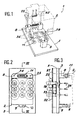
- FIG. 1 shows a power contactor 1 which comprises a box or male part 2 and its support base 3.
- This box 2 contains a relay (not shown) which makes it possible to switch the electrical energy received in three-phase form over the three terminals on the left or on the three terminals on the right (input terminals) to the three central terminals which constitute the output terminals, to an electrical distribution device of which the base or female part is part 3.
- the electrical energy can come from various sources of power which are two main generators which operate only when the engines of the aircraft are running, a runway generator for starting the engines and a on-board auxiliary generator which operates only in the absence of the runway generator.
- the input-output terminals of the housing or male part 2 are constituted by pins 36 which are housed in sockets 14 of the base or female part 3. These pins 36 are integral with the housing and will not be described more precisely because they are not part of the invention.
- the housing 2 has externally and laterally fixing lugs 38, 39 and 40 which cooperate with feet 8 and 9 secured to the base 3 by means of tapped holes in the feet 8 and 9 and of screws passing through the fixing lugs. Only the screw 6 associated with the foot 9 has been shown ( Figure 3).
- the base 3 comprises a base 5 of insulating material which is pierced with nine holes such as that referenced 12, holes which serve as housing for the female sockets 14.
- the base 3 has, on the housing side 2, two feet 8 and 9 for supporting and holding this box which are fixed to the base. To this end, these feet are pierced with tapped holes 34 and 35 for the foot 8 and 10 for the foot 9 into which are screwed screws associated with the housing 2.
- the foot 8 has the shape of a U whose lateral branches are attached to the base.
- the transverse branch is designed to receive a multi-pin connector in a socket 11 for low currents.
- the base 3 can be fixed in a removable manner on the shell of the electrical distribution apparatus by appropriate means (not shown), which facilitates the initial assembly.
- each female contact includes the following elements. First a hole 12 drilled in the base 5 and two bores 25 and 26 of diameter greater than that of the hole 12 arranged on the side of the male contact. In this hole and the bore 25 is disposed a bushing 14 comprising a hollow upper part 16 and a hollow bottom part 17 separated by a solid part forming a collar 15. The bottom of each hollow part is pierced with a hole 27 or 28 which serves to evacuate water and dirt which can accumulate in the bottom.
- the lower part 17 is a cylinder of revolution and is used to establish electrical contact with a flexible stranded conductor 18, for example by crimping.
- the upper part 16, also a cylinder of revolution, is designed to cooperate with a male pin 36.
- the external wall of the sleeve 14 is provided with a circular groove 29 to accommodate a ring elastic or clip 19. This ring 19 serves to retain in place the sleeve 14 in the hole 12 while allowing it a certain limited vertical movement downwards.
- the collar 15 plays a similar role in limiting the upward movement of the sleeve 14.
- the thickness of the wall of the upper part 16 is greater than that of the lower part 17.
- the upper part 16 is capped with an elastic seal 20 which fits into the first bore 26, this seal having a circular central opening 30, the center of which is on the axis of revolution of the sleeve.
- the upper face of the seal 20 is chamfered around its periphery.
- the underside of the seal is flush with the rounded upper periphery of the sleeve 14.
- the thickness of the elastic annular seal 20 is greater than the depth of the first bore 26 so that the seal 20 by elastic deformation comes to press the sleeve 14 and the immobilize in its working position by locking the ring 19 against the shoulder of the second bore 25 when the male part with pins or case 2 is kept pressed against the base 5 of the female part or base 3.
- the lower part 17 is extended downwards by the multi-strand cable 18 which passes through a hole 31 in a plate 21 which serves to support toroidal windings such as those referenced 22, 32 and 33 ( Figures 4 and 3).
- Each toroidal coil surrounds a conductor and is used to measure the intensity of current flowing through it.
- the toroidal windings 22 and 32, associated with the end conductors are arranged on one side of the plate 21, that remote from the base 3 while the winding 33, associated with the central conductor, is disposed between the plate 21 and the base 5.
- the plate 21 is held in place relative to the base 3 by any suitable means.
- This plate 21 may for example be a plate for supporting printed circuits and is therefore relatively rigid.
- the socket 14 is made of copper and the internal wall of the upper part 16 is covered with a thin layer of gold to improve the contact between the male part 36 and the socket 14.
- the base 3 is made of composite materials which are known by the names of RITON and DELMAT.
- the clip 19 is preferably made of steel and the elastic seal 20 is made of an elastomeric compound.
- the male contacts 36 of the contactor 2 fit into the corresponding sockets 14, the sockets being pushed down until the clip 19 rests on the shoulder of the bore 25.
- the underside of the housing 2 comes to rest on the elastic seals 20, the periphery of the central opening moves towards the bushing and comes to block it in the low position or working position while leaving a certain clearance due to the elasticity of the attached.
- the housing 2 is held in position by screws which are associated with it and which are screwed into the tapped holes 10, 34 and 35 carried by the feet 8 and 9.
- threaded holes 10, 34 and 35 and the corresponding screws can be replaced by any other equivalent means which ensures a removable fixing.
Landscapes
- Engineering & Computer Science (AREA)
- Power Engineering (AREA)
- Physics & Mathematics (AREA)
- Electromagnetism (AREA)
- Connector Housings Or Holding Contact Members (AREA)
Claims (7)
- Mit Buchsen (14) versehener Sockel (3) eines Leistungsschaltglieds (1) in Verbindung mit einem mit Stiften (36) versehenen Stiftteil (2), wobei der Buchsenteil in Höhe jeder Buchse (14) und den Stiften zugewandt eine erste Bohrung (26) aufweist, die koaxial zu dem Loch (12) verläuft, in dem die Buchse (14) sitzt, dadurch gekennzeichnet, daß die erste Bohrung (26) einen elastischen Dichtungsring (20) enthält, dessen Dicke größer als die Tiefe der ersten Bohrung (26) ist und die durch ihre elastische Verformung die Buchse (14) in ihre Arbeitsstellung drücken und dort halten kann, wenn der Stiftteil (2) und der Buchsenteil des Schaltglieds (1) zusammengesteckt werden.
- Sockel (3) nach Anspruch 1, dadurch gekennzeichnet, daß er eine flache Basis (5) enthält, die eine Vielzahl von Buchsenlöchern (12) besitzt, die auf der Seite der Stifte in je einer zweiten Bohrung (25) und in der ersten Bohrung (26) endet, wobei die zweite Bohrung (25) einen geringeren Durchmesser als die erste Bohrung (26) besitzt und wobei eine Buchse (14) in jedes Loch (12) eingesetzt ist, die an ihren beiden Enden je einen hohlen zylindrischen Bereich besitzt, nämlich einen Bereich (16), um den entsprechenden Stift (36) aufzunehmen, und den anderen Bereich (17), um den Anschluß an einen Leiter (18) durchzuführen, wobei die Buchse auf der Seite des Leiters einen Außenkragen (15), der als Anschlag gegen die Basis (5) dient, und auf der Seite der Stifte eine äußere ringförmige Rinne (29) enthält, um eine elastischen Ring oder Clip (19) aufzunehmen, der als Halteorgan in Anschlag gegen die Schulter der zweiten Bohrung (25) dient.
- Sockel (3) nach Anspruch 2, dadurch gekennzeichnet, daß der elastische Dichtungsring (20) eine Dicke hat, die so gewählt ist, daß der elastische Ring (19) an der Schulter der zweiten Bohrung (25) anliegt, wenn der Stiftteil (2) gegen die Basis (5) drückt.
- Sockel (3) nach einem beliebigen der Ansprüche 2 oder 3, dadurch gekennzeichnet, daß die Basis (5) Befestigungsmittel (8, 9, 10, 34, 35) für den Stiftteil (2) besitzt.
- Sockel (3) nach Anspruch 4, dadurch gekennzeichnet, daß die Befestigungsmittel von Füßen (8, 9) gebildet werden, die auf der Basis (5) sitzen und auf denen sich der Stiftteil (2) abstützt.
- Sockel (3) nach einem beliebigen der Ansprüche 2 bis 5, dadurch gekennzeichnet, daß die Leiter (18) mit ihrer Buchse (14) durch ringförmige Wicklungen (22, 32, 33) hindurch montiert sind, die zur Messung der in den Leitern (18) fließenden Ströme dienen.
- Sockel (3) nach Anspruch 2, dadurch gekennzeichnet, daß die hohlen Bereiche (16, 17) der Buchsen (14) in Höhe ihres Grundes Ableitungslöcher (27, 28) besitzen.
Applications Claiming Priority (2)
| Application Number | Priority Date | Filing Date | Title |
|---|---|---|---|
| FR8717290 | 1987-12-11 | ||
| FR8717290A FR2624648B1 (fr) | 1987-12-11 | 1987-12-11 | Socle de contacteur de puissance a broches |
Publications (2)
| Publication Number | Publication Date |
|---|---|
| EP0320355A1 EP0320355A1 (de) | 1989-06-14 |
| EP0320355B1 true EP0320355B1 (de) | 1993-03-24 |
Family
ID=9357772
Family Applications (1)
| Application Number | Title | Priority Date | Filing Date |
|---|---|---|---|
| EP19880403068 Expired - Lifetime EP0320355B1 (de) | 1987-12-11 | 1988-12-05 | Sockel für Leistungsschutz mit Steckern |
Country Status (3)
| Country | Link |
|---|---|
| EP (1) | EP0320355B1 (de) |
| DE (1) | DE3879640T2 (de) |
| FR (1) | FR2624648B1 (de) |
Cited By (1)
| Publication number | Priority date | Publication date | Assignee | Title |
|---|---|---|---|---|
| BE1032074B1 (de) * | 2023-10-20 | 2025-05-19 | Phoenix Contact Gmbh & Co | Elektrisches Einbaugerät zur automatisierten Montage auf einer Montageplatte, System mit Montageplatte und wenigstens einem elektrischen Einbaugerät, und Verfahren zur automatisierten Montage eines solchen Systems |
Families Citing this family (3)
| Publication number | Priority date | Publication date | Assignee | Title |
|---|---|---|---|---|
| ITMI981310A1 (it) * | 1998-06-09 | 1999-12-09 | Bticino Spa | Struttura con zoccolo di base e zoccolo aggiuntivo per collegare un dispositivo elettrico rimovibile accessoriato |
| US8987948B2 (en) * | 2010-02-02 | 2015-03-24 | Hamilton Sundstrand Corporation | Bus bar assembly |
| CN102790432A (zh) * | 2011-05-20 | 2012-11-21 | 人民电器集团上海有限公司 | 运用磁电耦合交变弱磁传感器技术的输变电装置 |
Family Cites Families (3)
| Publication number | Priority date | Publication date | Assignee | Title |
|---|---|---|---|---|
| BE563966A (de) * | 1957-03-12 | |||
| US3328648A (en) * | 1966-04-29 | 1967-06-27 | Ite Circuit Breaker Ltd | Combination plug-in block with current transformers |
| DE3524408A1 (de) * | 1985-07-09 | 1987-01-22 | Deere & Co | Platte zur aufnahme von elektrikbauteilen |
-
1987
- 1987-12-11 FR FR8717290A patent/FR2624648B1/fr not_active Expired - Fee Related
-
1988
- 1988-12-05 DE DE19883879640 patent/DE3879640T2/de not_active Expired - Fee Related
- 1988-12-05 EP EP19880403068 patent/EP0320355B1/de not_active Expired - Lifetime
Cited By (1)
| Publication number | Priority date | Publication date | Assignee | Title |
|---|---|---|---|---|
| BE1032074B1 (de) * | 2023-10-20 | 2025-05-19 | Phoenix Contact Gmbh & Co | Elektrisches Einbaugerät zur automatisierten Montage auf einer Montageplatte, System mit Montageplatte und wenigstens einem elektrischen Einbaugerät, und Verfahren zur automatisierten Montage eines solchen Systems |
Also Published As
| Publication number | Publication date |
|---|---|
| DE3879640D1 (de) | 1993-04-29 |
| FR2624648A1 (fr) | 1989-06-16 |
| FR2624648B1 (fr) | 1990-03-30 |
| DE3879640T2 (de) | 1993-07-01 |
| EP0320355A1 (de) | 1989-06-14 |
Similar Documents
| Publication | Publication Date | Title |
|---|---|---|
| FR2952762A1 (fr) | Ensemble de montage de contacteur avec caracteristiques thermiques ameliorees | |
| FR2700416A1 (fr) | Dispositif à semiconducteurs comportant un élément semiconducteur sur un élément de montage. | |
| EP0005087A1 (de) | Verbindungszubehörsystem für Stromschiene mit asymmetrischem Profil | |
| EP0320355B1 (de) | Sockel für Leistungsschutz mit Steckern | |
| FR2982712A1 (fr) | Plaque de distribution d'energie electrique comprenant une barre de distribution protegee. | |
| FR2589636A1 (fr) | Bloc connecteur amovible a utiliser dans un assemblage de connecteurs | |
| FR2742918A1 (fr) | Dispositif de raccordement d'un conducteur exterieur tel un cable a une plage de contact d'un appareil electrique | |
| FR2557380A1 (fr) | Element connecteur electrique | |
| EP2745661B1 (de) | Elektrische verbindungsvorrichtung, anordnung mit einer solchen vorrichtung und elektronikplatine sowie verfahren zum elektrischen anschluss einer elektronikplatine | |
| EP0633588B1 (de) | Zusatzanschlussgerät | |
| EP0231696A1 (de) | Regler, insbesondere für Turbomaschine mit elektrohydraulischer Kopplungseinrichtung für schnelle Montage | |
| FR2681732A1 (fr) | Systeme de connexion electrique pour cable plat. | |
| EP0320356B1 (de) | Leistungsreihenklemme, die Steckerstifte trägt | |
| FR2706684A1 (fr) | Bornier de raccordement électrique de câbles d'alimentation en énergie électrique. | |
| FR2608850A1 (fr) | Boitier de raccordement pour cables electriques | |
| FR2595167A1 (fr) | Dispositif de mise en parallele de composants electroniques de puissance | |
| FR2805409A1 (fr) | Dispositif de distribution de puissance comportant des barres appliquees sur une platine | |
| EP0829927B1 (de) | Vorrichtung zur Verbindung einer Stromschiene mit einem elektrischen Leiter | |
| EP0676915B1 (de) | Erdungsanordnung für Automatisierungsgerät | |
| FR2816764A1 (fr) | Dispositif de raccordement pour deux cables electriques | |
| FR3157695A1 (fr) | Dispositif de connexion électrique | |
| WO2017032814A1 (fr) | Élément de commutation pour plaque de distribution d'énergie électrique et boîtier de distribution d'énergie électrique doté d'un tel élément de commutation | |
| EP0886339A1 (de) | Tragschiene für elektrische oder elektronische Geräte und Gehäuse mit einer solchen Tragschiene | |
| FR2695258A1 (fr) | Borne de connexion pour appareillage électrique. | |
| FR2556892A1 (fr) | Bloc de bretelle anti-vibratoire a manchon sertissable pour cable de ligne electrique |
Legal Events
| Date | Code | Title | Description |
|---|---|---|---|
| PUAI | Public reference made under article 153(3) epc to a published international application that has entered the european phase |
Free format text: ORIGINAL CODE: 0009012 |
|
| AK | Designated contracting states |
Kind code of ref document: A1 Designated state(s): DE FR GB IT NL |
|
| 17P | Request for examination filed |
Effective date: 19890623 |
|
| 17Q | First examination report despatched |
Effective date: 19910904 |
|
| GRAA | (expected) grant |
Free format text: ORIGINAL CODE: 0009210 |
|
| AK | Designated contracting states |
Kind code of ref document: B1 Designated state(s): DE FR GB IT NL |
|
| ITF | It: translation for a ep patent filed | ||
| REF | Corresponds to: |
Ref document number: 3879640 Country of ref document: DE Date of ref document: 19930429 |
|
| GBT | Gb: translation of ep patent filed (gb section 77(6)(a)/1977) |
Effective date: 19930512 |
|
| PLBE | No opposition filed within time limit |
Free format text: ORIGINAL CODE: 0009261 |
|
| STAA | Information on the status of an ep patent application or granted ep patent |
Free format text: STATUS: NO OPPOSITION FILED WITHIN TIME LIMIT |
|
| 26N | No opposition filed | ||
| PGFP | Annual fee paid to national office [announced via postgrant information from national office to epo] |
Ref country code: GB Payment date: 19941121 Year of fee payment: 7 Ref country code: DE Payment date: 19941121 Year of fee payment: 7 |
|
| PGFP | Annual fee paid to national office [announced via postgrant information from national office to epo] |
Ref country code: FR Payment date: 19941220 Year of fee payment: 7 |
|
| PGFP | Annual fee paid to national office [announced via postgrant information from national office to epo] |
Ref country code: NL Payment date: 19941231 Year of fee payment: 7 |
|
| PG25 | Lapsed in a contracting state [announced via postgrant information from national office to epo] |
Ref country code: GB Effective date: 19951205 |
|
| PG25 | Lapsed in a contracting state [announced via postgrant information from national office to epo] |
Ref country code: NL Effective date: 19960701 |
|
| GBPC | Gb: european patent ceased through non-payment of renewal fee |
Effective date: 19951205 |
|
| PG25 | Lapsed in a contracting state [announced via postgrant information from national office to epo] |
Ref country code: FR Effective date: 19960830 |
|
| NLV4 | Nl: lapsed or anulled due to non-payment of the annual fee |
Effective date: 19960701 |
|
| PG25 | Lapsed in a contracting state [announced via postgrant information from national office to epo] |
Ref country code: DE Effective date: 19960903 |
|
| REG | Reference to a national code |
Ref country code: FR Ref legal event code: ST |
|
| PG25 | Lapsed in a contracting state [announced via postgrant information from national office to epo] |
Ref country code: IT Free format text: LAPSE BECAUSE OF NON-PAYMENT OF DUE FEES;WARNING: LAPSES OF ITALIAN PATENTS WITH EFFECTIVE DATE BEFORE 2007 MAY HAVE OCCURRED AT ANY TIME BEFORE 2007. THE CORRECT EFFECTIVE DATE MAY BE DIFFERENT FROM THE ONE RECORDED. Effective date: 20051205 |