EP0320392A1 - Vorrichtung zur gleichzeitigen Thermoformung von mindestens einer Reihe von Behältern aus thermoplastischem Kunststoff mit einer dekorativen Banderole - Google Patents
Vorrichtung zur gleichzeitigen Thermoformung von mindestens einer Reihe von Behältern aus thermoplastischem Kunststoff mit einer dekorativen Banderole Download PDFInfo
- Publication number
- EP0320392A1 EP0320392A1 EP88403125A EP88403125A EP0320392A1 EP 0320392 A1 EP0320392 A1 EP 0320392A1 EP 88403125 A EP88403125 A EP 88403125A EP 88403125 A EP88403125 A EP 88403125A EP 0320392 A1 EP0320392 A1 EP 0320392A1
- Authority
- EP
- European Patent Office
- Prior art keywords
- carriage
- partial
- partial carriage
- guide
- installation according
- Prior art date
- Legal status (The legal status is an assumption and is not a legal conclusion. Google has not performed a legal analysis and makes no representation as to the accuracy of the status listed.)
- Granted
Links
- 239000012815 thermoplastic material Substances 0.000 title claims description 3
- 230000015572 biosynthetic process Effects 0.000 title 1
- 238000009434 installation Methods 0.000 claims abstract description 40
- 238000000465 moulding Methods 0.000 claims abstract description 38
- 238000007493 shaping process Methods 0.000 claims abstract description 15
- 238000003856 thermoforming Methods 0.000 claims description 46
- 238000004804 winding Methods 0.000 claims description 34
- 229920001169 thermoplastic Polymers 0.000 claims description 15
- 239000004416 thermosoftening plastic Substances 0.000 claims description 15
- 238000012546 transfer Methods 0.000 claims description 9
- 238000011144 upstream manufacturing Methods 0.000 claims description 9
- 230000005540 biological transmission Effects 0.000 claims description 5
- 210000000078 claw Anatomy 0.000 claims description 4
- 230000000149 penetrating effect Effects 0.000 claims description 3
- 238000005096 rolling process Methods 0.000 claims description 3
- 238000001514 detection method Methods 0.000 claims description 2
- 238000006073 displacement reaction Methods 0.000 claims description 2
- 238000013519 translation Methods 0.000 claims description 2
- 230000010355 oscillation Effects 0.000 description 5
- 238000013461 design Methods 0.000 description 3
- 240000008042 Zea mays Species 0.000 description 2
- 238000013459 approach Methods 0.000 description 2
- 238000012795 verification Methods 0.000 description 2
- 206010016322 Feeling abnormal Diseases 0.000 description 1
- 230000001174 ascending effect Effects 0.000 description 1
- 230000008878 coupling Effects 0.000 description 1
- 238000010168 coupling process Methods 0.000 description 1
- 238000005859 coupling reaction Methods 0.000 description 1
- 238000005034 decoration Methods 0.000 description 1
- 230000006866 deterioration Effects 0.000 description 1
- 210000000056 organ Anatomy 0.000 description 1
- 230000002093 peripheral effect Effects 0.000 description 1
- 230000000284 resting effect Effects 0.000 description 1
- 230000000717 retained effect Effects 0.000 description 1
- 238000007789 sealing Methods 0.000 description 1
- 238000000926 separation method Methods 0.000 description 1
- 239000007787 solid Substances 0.000 description 1
Images


Classifications
-
- B—PERFORMING OPERATIONS; TRANSPORTING
- B29—WORKING OF PLASTICS; WORKING OF SUBSTANCES IN A PLASTIC STATE IN GENERAL
- B29C—SHAPING OR JOINING OF PLASTICS; SHAPING OF MATERIAL IN A PLASTIC STATE, NOT OTHERWISE PROVIDED FOR; AFTER-TREATMENT OF THE SHAPED PRODUCTS, e.g. REPAIRING
- B29C51/00—Shaping by thermoforming, i.e. shaping sheets or sheet like preforms after heating, e.g. shaping sheets in matched moulds or by deep-drawing; Apparatus therefor
- B29C51/16—Lining or labelling
- B29C51/165—Lining or labelling combined with the feeding or the shaping of the lining or the labels
- B29C51/167—Lining or labelling combined with the feeding or the shaping of the lining or the labels of a continuous strip
Definitions
- thermoforming installation is, for example, known from French patent 2,454,892.
- the support carriage in this case comprises a horizontal plate which, in the working position, is located under the thermoplastic strip and can perform reciprocating movements perpendicular to the vertical plane determined by the vertical axes of the forming chambers. a transverse row of said chambers, to introduce into each of the pre-winding chambers one end of a banner which will then, by air suction, be retained against the rod of the shaping member and entirely introduced into said chamber by a rotation of said rod.
- the support carriage can be extracted from its working position towards the reel of mother tape installed at a fixed station, by rolling on raised rails.
- horizontal whose level corresponds to that of the position of the pre-winding chambers and which extend in directions parallel to the transverse vertical plane comprising the axes of the chambers of a row of pre-winding or forming chambers. Due to the width of the horizontal plate of the support carriage and the existence of these hanging rails, access to the pairs of introduction rollers and to the transverse cutting knives remains problematic and the difficulty of access to the chambers form of the molding block and the pre-winding chambers of the support block remains unchanged.
- the known installation does not make it possible to verify, outside the service position, and at an easily accessible location, the operation of all of the elements contributing to the longitudinal and transverse cutting of a banner and to the introduction of the latter in a forming chamber of the molding block.
- the object of the present invention is to eliminate these drawbacks and to propose a thermoforming installation in which the various elements ensuring the transverse cutting of the banners, their preforming and the introduction thereof into the forming chambers are not only easily accessible. but can also be brought into working order outside their normal working position in the thermoforming installation.
- the molding block rests on the press plate via the support block of the prerolling and streamer transfer unit and is fixed in a normally non-removable manner on the upper end of said support block;
- the movable carriage of the unit for the introduction and transverse cutting of the banners comprises two partial carriages arranged one behind the other in the direction of a row of pre-winding chambers and the first partial carriage of which rests in position of service, entirely on at least one lower horizontal slide of the support block and is fixed thereon in a removable manner, has a vertical wall which is provided with access slots in the prerolling chambers and delimits a lateral part of these ci and comprises, upstream of each slot, one of the pairs of introduction rollers and, downstream of said slot, a transverse cutting knife which cooperates with an edge of said slot, acting as a counter blade, and a means for controlling the transverse cutting knives, and of which the second partial carriage, on the one hand, is guided on rails provided on the ground on which the
- the first partial carriage has a very small width and when it has left its service position, is very easily accessible since the second partial carriage is always spaced from its front face and, in the spaced-out position called verification, only supports one of its ends, the other end of which then rests on the support block of the prerolling and streamer transfer unit.
- This new design also enables the assembly of the first partial carriage and the support block with the molding block to be taken out of their service position by making one of the ends of the first partial carriage normally fixed on the support block bear. the support and locking stop of the second partial carriage, and the other end by the press plate.
- thermoforming the containers from a thermoplastic strip and successively comprising a station for preheating the thermoplastic strip, a station for thermoforming containers, a station for filling the containers with a product, a station for sealing the containers and a station for cutting filled and sealed containers, are of a design widely known in the state of the art (see for example French patent 2,034,915) so that it is not necessary to describe them in more detail .
- the object of the present invention relates more particularly to the thermoforming means and the decoration of the thermoplastic containers using decorative banners.
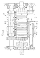
- FIG 1 there is shown schematically a press plate 1 provided in the thermoforming station in below the path (arrow F1) of the thermoplastic strip, not shown, this press plate being sequentially driven by upward movements in a high position known as thermoforming and downward movement in a low position known as demoulding, being guided vertically by four column 2 .
- a molding block 3 which preferably comprises two rows 4, 5 of forming chambers 6, rows extending transversely with respect to the longitudinal extension of the thermoforming installation, c ' that is to say perpendicular to the direction F1 of stepwise movement of the thermoplastic strip.
- Each forming chamber 6 of the molding block has a vertical wall, an upper opening and a lower opening, the latter being capable of being closed by the head 7 of a shaping member 8 which below this head 7 has a rod tubular 9 guided on a solid vertical rod 10 whose upper end is at the bottom opening or bottom of the forming chamber 6 and whose lower end is secured to a support block 11 of the prerolling 12 of the banners 13.
- the molding block 3 rests on the upper end of the support block 11 and is fixed therein in a normally non-removable manner while the support block 11 at its lower end is mounted removably on the press plate 1 which has at this location a transverse recess 14 open upwards and at the lateral ends.
- the support block 11 of the pre-winding and transfer unit 12 for the streamers 13 comprises below the molding block 3 as many pre-winding chambers 15 as the molding block 3 has forming chambers 6.
- Each of the pre-winding chambers 15 is aligned coaxially with one of the forming chambers 6 so that the vertical wall of each prerolling chamber 15 delimits a homothetic periphery to that of the forming chamber 6, but slightly less than the periphery of the latter, so as to constitute by its upper edge, an annular retaining shoulder which at the same time delimits the bottom opening of the forming chamber 6 and which prevents the streamer 13 from returning to the prerolling chamber 15.
- the tubular rod 9 of the shaping member 8 has in its central part which, when its head 7 closes the bottom of a forming chamber 6, is located at the lower end of the prerolling chamber 15 and below the vertical access slot 16 in this chamber 15, several driving tabs 17 projecting radially from said tubular rod 9 and intended to act as transfer member and to push the banner 13 located in the prerolling chamber 15 in the forming 6.
- the upward and downward movements of the driving cleats 17 are controlled using a cross member 18 whose ends are moved vertically using control means 19, part of which is provided below the support block 11 and housed in the transverse recess 14 of the press plate 1.
- the support block 11 is removably mounted on the press plate 1 and can be fixed on the latter by means of a locking jack 20, the cylinder of which is integral with the plate 1 and the rod of which is engages in a notch in the support block.
- This support block 11 can move horizontally and parallel to the vertical plane comprising the axes of a row of forming chambers 4 or 5 by resting on horizontal guides 21, 22 of the press plate 1.
- the device for cutting, preforming and transferring the banners 13 also comprises a unit for the introduction and transverse cutting of the banners 13 from individual strips 24.
- This introduction unit 23 has a plurality of transverse cutting knives 25 capable of cooperating with a counter blade 26 for transversely cutting the rear end of a banner 13 introduced into the chamber corresponding pre-winding 15 through a vertical access slot 16; a plurality of pairs of introduction rollers 27a, 27b with axes parallel to the vertical access or introduction slots 16 and arranged upstream just in front of a corresponding slot 16 and capable of each sequentially driving an individual strip 24 pinched between its two rollers 27a, 27b, with a pitch equal to the length of a banner 13; toothed wheels 28a, 28b each secured to one of the introduction rollers 27a, 27b and meshing with one another and with a toothed wheel of the neighboring pair of rollers 27a, 27b; control means 29, 30 for sequentially driving the knives 25 and the toothed wheels 28a, 28b; and a first
- This first partial support carriage 31 comprises a vertical support wall 32 disposed against the support block 11 so as to constitute, by one of its vertical faces, part of the vertical wall of the prewinding chambers 15.
- the support block 11 comprises two parallel rows of pre-winding chambers 15
- the vertical support wall 32 of the first partial carriage 31 has in cross horizontal section the shape of a U which, by its wings, covers the transverse vertical faces of the support block 11 between the upper face of the press plate 1 and the upper end of said support block 11.
- the vertical wall 32 is formed by the bottom of a U-shaped section 33, the lateral wings 34 extend horizontally away from the support block 11.
- This U-shaped section 33 also rests by its lower wing on the upper wing of another U-shaped section 35 which also part of the first partial carriage 31 which by its lower wing, in the service position, rests entirely on lower horizontal slides 36, 37 of the lower part of the support block 11.
- This first partial carriage 31 can be made integral with the support block by means of a jack locking 38 whose cylinder is for example fixed on the support block 11 and whose rod engages in a notch of the first partial carriage 31.
- the horizontal slides 36, 37 are also parallel to the vertical plane comprising the axes of the chambers forming 6 and pre-winding 15.
- the pairs of vertical rollers 27a, 27b are supported by the horizontal upper wing 34 of the U-shaped section 33 and are located at the same level as the prerolling chambers 15 and the knives 25 located the other side of the vertical support wall 32 and actuated by means of a stud 39 and a rod 40 controlled by the rod 41 of a jack 42 mounted on the first partial carriage 31.
- a second partial support carriage 43 is arranged laterally with respect to the molding block 3 and to the direction of advance F1 of the thermoplastic strip and in alignment with the first partial carriage 31.
- the second partial carriage 43 comprises on the side of the thermoforming installation, that is to say opposite the press plate 1 and of the first partial carriage 31, a support and locking stop 44 capable of being coupled to the corresponding lateral end 45 of the first partial carriage 31.
- This stop 44 comprises a locking cylinder 46 whose cylinder is for example fixed on the second partial carriage 43 and whose rod engages in a notch in the lateral end 45 of the first partial carriage 31.
- the second partial support carriage 43 is guided on horizontal rails 47 provided on the ground 48 on which the thermoforming installation rests and extending parallel to the guide rails 36, 37 of the first partial carriage 31 and in the vertical plane comprising the vertical axes of the forming chambers 6 of the same row of chambers 4 or 5.
- a motor or other rotary control means 49 On this second partial carriage 43 is provided a motor or other rotary control means 49, the output of which is connected via a cardan link 50 and telescopic shafts 51 at the entry of the transmission mechanism 52 provided on the first partial carriage 31 and cooperating via the toothed wheels 28a, 28b with the pairs of introduction rollers 27a, 27b.
- the second partial carriage 43 further comprises a drive motor 53 which moves it relative to the thermoforming installation.
- the output of this motor 53 attacks, by means of a screw 54, a control wheel 55 which is free in rotation but integral in translation with the second partial carriage 43.
- This screw wheel 55 cooperates with a horizontal threaded rod 56, one end of which is fixed to a lateral flange 57 of the frame of the thermoforming installation and which extends parallel to the rails 47 of the second partial carriage 43.
- the support block 11 has on its lower part penetrating into the transverse recess 14 of the press plate 1 the control means 19 for the cross member 18 ensuring the rise and fall of the 'shaping member 8 with respect to the molding block 3.
- control means 19 comprise, per row of shaping members 8, two vertical guide tubes 58 integral with the lower lateral ends of the support block 11, two vertical rods 59 each sliding in one of the guide tubes 58, connected at their upper end to the horizontal control cross member 18 and having, at their lower part, a rack 59a which cooperates with a toothed sector 60 articulated, on the one hand, on an axis 61 integral with the support block 11 and, on the other hand, on the rod of a jack 62 whose cylinder is also articulated on said block 11.
- a connecting rod 63 connects the two toothed sectors 60 to avoid use a second control cylinder.
- the second partial carriage 43 is advantageously designed so as to be able to receive several reels of mother strip 64 (four in the example shown) each mounted on a transport carriage 65 with free wheels and capable of rolling and being oriented on the floor 66 of the second partial carriage 43 while being guided by a guide 67 extending parallel to the direction of movement F1 of the thermoplastic strip and perpendicular to the direction of movement of the partial carriages 31 and 43.
- the reel of mother strip 64 is arranged on the second partial carriage 43 so that its axis is parallel to the guide rails 47 of said second carriage 43 and the axes of the coils 64 are aligned by pair of coils 64.
- the second partial carriage 43 advantageously comprises, above the location of the reels of mother strip 64, a frame 68 supporting the cutting unit 69 of at least one mother strip 70 and preferably of two mother strip 70 , 71 in individual strips 24 as well as the adjustable position guide roller 72 for each of the individual strips 24 and the rollers 73 or return bars 74, 75 for the latter.
- the second partial carriage 43 therefore comprises, as a longitudinal cutting unit 69, a counter-blade cylinder 76 and a cylinder with annular blades 77 whose blades 78 cooperate with the counter blades 79 of the cylinder 76.
- a guide device 80 is provided. for the mother strip 70, 71 and for the individual strips 24 leaving the longitudinal cutting unit 69, this guide device 80 having to return the individual strips 24 alternately to one side and to the other (to the left and towards the right in Figures 9 and 10).
- the cylinders with counter-blades 76 and blades 77 are arranged on the second partial carriage 43 so that their axes are parallel to the guide rails 47 of said second carriage 43.
- a guide cylinder 81 Upstream of the counterblade cylinder 76 is provided a guide cylinder 81 which forms part of the device 80 and defines with the periphery of the counterblade cylinder 76 a passage slot 82.
- a horizontal guide plate 83 is arranged upstream of the guide cylinder 81 and approaches tangentially to the upper generator thereof.
- Another guide plate 84 is disposed in an inclined manner above the guide cylinder and approaches its lower end by the passage slot 82.
- the cylinder 76 comprises a pair of annular grooves 85, 86 in which engage, on the one hand, in front and downstream of the contact zone of the blades 78 and against -blades 79 and in each pair of odd grooves, separation claws 87 extended outwards (left) by a guide plate 88 and on the other hand, at the upper part of the counter-blade cylinder 76, in each pair pair of grooves, release claws 89 extended outward (right) by a guide plate 90.
- the mother strip 70, 71 and the individual strips are guided towards the cylinders 76, 77 of the longitudinal cutting unit 69 and then to either side of this unit 69 using several endless belts 91 (of circular cross section) which pass around the guide cylinder 81 and several deflection rollers 92, 93, 94 , 95, 96 and between the counter-blade 76 and blade 77 cylinders as well as th Between the counterblade cylinder 76 and the guide cylinder 81.
- each endless belt 91 is offset laterally as they pass between the counterblade cylinders 76 and blades 77 and that these belts 91 are guided at least partially in annular grooves 97 provided either on the guide cylinder 81 or on the cylinders 76 and 77.
- This follower device 98 comprises the guide roller with adjustable position 72 which at the same time plays the role of a tension roller fixed on the end of a double lever 99 the other end of which carries a counterweight 100 and, in his fall passes in front a photoelectric cell or other detection element 101 making it possible to ascertain a failure in advancement of the individual strip 24 or the breakage thereof.
- the follower device 98 further comprises an oscillating platform 102 which is articulated at its outer edge on a horizontal axis 103 carried by the second partial carriage 43 and parallel to the guide rails 47 thereof and to the slides 21, 22 and 36, 37.
- This pivot axis 103 coincides, moreover, with the horizontal axis of the deflection bar 75 which, in FIG. 10, has been shown slightly above the horizontal pivot axis 103.
- the oscillating platform 102 Near its inner edge (relative to the vertical plane passing through the axes of the forming chambers of a row of chambers 4 or 5), the oscillating platform 102 has as many deflection rollers 73 as there are individual strips 24 per row of chambers 4 or 5, but for the clarity of the drawing, a single deflection roller 73 has been shown, the axis of this roller 73 being perpendicular to the oscillating platform 102 whose inner edge 102a is located in the extension of a row of chambers 4 or 5 and positio n horizontal of the platform 102 approximately halfway up between the high position and the low position of the pairs of introduction rollers 27a, 27b, corresponding respectively to the high thermoforming position and to the low demolding position of the block molding 3.
- the inner edge 102 of the oscillating platform 102 is connected by a linkage link 104 to a vertical lateral face. 3a of the molding block 3 or to another element according to the upward and downward movements of the latter.
- This linkage link 104 comprises an oscillation shaft 105 parallel to the pivot axis 103 of the platform 102 and carried in bearings not shown of the second partial carriage 43.
- On this oscillation shaft 105 are reasonably fixed several arms 106 , 107, 108, 109 which are the same length and parallel to each other and, at their free end, are each articulated at the upper end of a connecting rod 110, 111, 112, 113 whose lower end carries a hinge pin 114, 115, 116, 117, parallel to the pivot axis 103 and the oscillation shaft 105 and aligned with each other.
- the connecting rod 110 cooperating with the first arm 106 located near the vertical lateral face 3a of the molding block 3 is connected by its lower articulation axis 114 to said lateral face 3a so that during the upward and downward movements of the block molding 3, the oscillation shaft 105 will execute an oscillation movement and transmit this movement to the other three arms 107, 108, 109 which are rigidly attached thereto.
- the other articulation axes 115, 116, 117 each carried by the lower end of a connecting rod 111, 112, 113 respectively engage in the oblong hole 118 of one of the three coupling fingers 119, 120, 121 which are fixed on the inner edge 102a in the extension of the oscillating platform 102 and respectively on the ends and the middle part of said platform 102.
- the up and down movements of the molding block 3 are transformed into similar movements rise and fall of the inner marginal part of the platform 102 which then oscillates around its pivot axis 103 while allowing the individual strip section 24 located downstream of the last deflection roller 73 to follow the ascending races almost exactly and descending from the pair of corresponding introduction rollers 27a, 27b.
Landscapes
- Engineering & Computer Science (AREA)
- Mechanical Engineering (AREA)
- Blow-Moulding Or Thermoforming Of Plastics Or The Like (AREA)
Applications Claiming Priority (2)
| Application Number | Priority Date | Filing Date | Title |
|---|---|---|---|
| FR8717355 | 1987-12-11 | ||
| FR8717355A FR2624429B1 (fr) | 1987-12-11 | 1987-12-11 | Installation de thermoformage simultane d'au moins une rangee de recipients en matiere thermoplastique munis chacun d'une banderole decorative |
Publications (2)
| Publication Number | Publication Date |
|---|---|
| EP0320392A1 true EP0320392A1 (de) | 1989-06-14 |
| EP0320392B1 EP0320392B1 (de) | 1991-10-16 |
Family
ID=9357802
Family Applications (1)
| Application Number | Title | Priority Date | Filing Date |
|---|---|---|---|
| EP88403125A Expired - Lifetime EP0320392B1 (de) | 1987-12-11 | 1988-12-09 | Vorrichtung zur gleichzeitigen Thermoformung von mindestens einer Reihe von Behältern aus thermoplastischem Kunststoff mit einer dekorativen Banderole |
Country Status (6)
| Country | Link |
|---|---|
| US (1) | US4840555A (de) |
| EP (1) | EP0320392B1 (de) |
| JP (1) | JPH01286818A (de) |
| DE (1) | DE3865646D1 (de) |
| ES (1) | ES2027406T3 (de) |
| FR (1) | FR2624429B1 (de) |
Cited By (1)
| Publication number | Priority date | Publication date | Assignee | Title |
|---|---|---|---|---|
| GB2322093A (en) * | 1997-02-12 | 1998-08-19 | Erca | Manufacture of receptacles incorporating a banderole of ornamentation |
Families Citing this family (1)
| Publication number | Priority date | Publication date | Assignee | Title |
|---|---|---|---|---|
| ES2391515B1 (es) * | 2011-02-11 | 2013-08-20 | Mecánica Y Tecnología Alimentaria, S.L. | Envase termoformado reciclable y envasadora para su fabricación. |
Citations (6)
| Publication number | Priority date | Publication date | Assignee | Title |
|---|---|---|---|---|
| FR2034915A1 (de) * | 1969-03-13 | 1970-12-18 | Intercan Sa | |
| FR2340191A1 (fr) * | 1976-02-04 | 1977-09-02 | Gatrun Anstalt | Dispositif de fabrication et de depot de banderoles |
| FR2425926A1 (fr) * | 1978-05-17 | 1979-12-14 | Tecca Sarl | Installation de thermoformage |
| FR2454892A1 (fr) * | 1979-04-28 | 1980-11-21 | Plastimecanique Sa | Machine d'emboutissage pour fabriquer des recipients dans une fouille thermoplastique |
| FR2595976A1 (fr) * | 1986-03-20 | 1987-09-25 | Paris Coop Laitiere Centrale | Dispositif de banderolage externe pour machines a thermoformer les recipients |
| FR2599668A1 (fr) * | 1986-06-09 | 1987-12-11 | Erca Holding | Dispositif de preformage et de transfert d'une banderole decorative dans une installation de thermoformage de recipients |
Family Cites Families (4)
| Publication number | Priority date | Publication date | Assignee | Title |
|---|---|---|---|---|
| US4009981A (en) * | 1975-11-10 | 1977-03-01 | Rosen Stanley R | Universal mold tooling system for thermoforming molds |
| US4674972A (en) * | 1984-03-30 | 1987-06-23 | Wagner Curtis D | Apparatus for thermoforming plastic articles |
| US4666394A (en) * | 1985-02-07 | 1987-05-19 | Mitsubishi Jukogyo Kabushiki Kaisha | Apparatus for thermally fixing the formed thermoplastic products |
| FR2602174B1 (fr) * | 1986-07-31 | 1988-11-18 | Erca Holding | Procede et dispositif de reglage de l'echauffement d'une bande thermoplastique utilisee dans un poste de thermoformage |
-
1987
- 1987-12-11 FR FR8717355A patent/FR2624429B1/fr not_active Expired - Lifetime
-
1988
- 1988-12-09 ES ES198888403125T patent/ES2027406T3/es not_active Expired - Lifetime
- 1988-12-09 US US07/281,789 patent/US4840555A/en not_active Expired - Fee Related
- 1988-12-09 DE DE8888403125T patent/DE3865646D1/de not_active Expired - Fee Related
- 1988-12-09 EP EP88403125A patent/EP0320392B1/de not_active Expired - Lifetime
- 1988-12-12 JP JP63312127A patent/JPH01286818A/ja active Pending
Patent Citations (6)
| Publication number | Priority date | Publication date | Assignee | Title |
|---|---|---|---|---|
| FR2034915A1 (de) * | 1969-03-13 | 1970-12-18 | Intercan Sa | |
| FR2340191A1 (fr) * | 1976-02-04 | 1977-09-02 | Gatrun Anstalt | Dispositif de fabrication et de depot de banderoles |
| FR2425926A1 (fr) * | 1978-05-17 | 1979-12-14 | Tecca Sarl | Installation de thermoformage |
| FR2454892A1 (fr) * | 1979-04-28 | 1980-11-21 | Plastimecanique Sa | Machine d'emboutissage pour fabriquer des recipients dans une fouille thermoplastique |
| FR2595976A1 (fr) * | 1986-03-20 | 1987-09-25 | Paris Coop Laitiere Centrale | Dispositif de banderolage externe pour machines a thermoformer les recipients |
| FR2599668A1 (fr) * | 1986-06-09 | 1987-12-11 | Erca Holding | Dispositif de preformage et de transfert d'une banderole decorative dans une installation de thermoformage de recipients |
Cited By (3)
| Publication number | Priority date | Publication date | Assignee | Title |
|---|---|---|---|---|
| GB2322093A (en) * | 1997-02-12 | 1998-08-19 | Erca | Manufacture of receptacles incorporating a banderole of ornamentation |
| GB2322093B (en) * | 1997-02-12 | 2001-11-07 | Erca | Thermoforming process and apparatus for receptacles |
| ES2170593A1 (es) * | 1997-02-12 | 2002-08-01 | Erca Formseal | Procedimiento e instalacion de formacion termica y de aplicacion de banderolas |
Also Published As
| Publication number | Publication date |
|---|---|
| EP0320392B1 (de) | 1991-10-16 |
| US4840555A (en) | 1989-06-20 |
| FR2624429A1 (fr) | 1989-06-16 |
| DE3865646D1 (de) | 1991-11-21 |
| JPH01286818A (ja) | 1989-11-17 |
| FR2624429B1 (fr) | 1990-05-25 |
| ES2027406T3 (es) | 1992-06-01 |
Similar Documents
| Publication | Publication Date | Title |
|---|---|---|
| EP1413530B1 (de) | Maschine zum Bewegen von Behältern vor Prüfungsvorrichtungen | |
| EP0248700B1 (de) | Verpackungsmaschine für "amerikanische" Schachteln | |
| FR2490602A1 (fr) | Systeme convoyeur rassemblant | |
| CH633761A5 (fr) | Dispositif pour empiler des objets plats, notamment des decoupes de boites pliantes. | |
| FR2569163A1 (fr) | Appareil pour l'empilage d'emballages en particulier dans les installations d'emballage au moyen d'un ruban de materiau thermoretractable | |
| EP2490965B1 (de) | Vorrichtung zur herstellung von produktchargen zu ihrer abfüllung in behältnisse | |
| CH362644A (fr) | Machine à voies multiples pour empaqueter des articles par enveloppement | |
| FR2765191A1 (fr) | Procede et machine de collage automatique d'un film plastique thermoretractable sur le fond d'une caisse ouverte | |
| EP0249550B1 (de) | Vorrichtung zum Vorformen und Übertragen einer Banderole in einer Maschine zum Warmverformen von Behältern | |
| CH547731A (fr) | Machine d'emballage. | |
| EP0320392B1 (de) | Vorrichtung zur gleichzeitigen Thermoformung von mindestens einer Reihe von Behältern aus thermoplastischem Kunststoff mit einer dekorativen Banderole | |
| EP0253737B1 (de) | Verfahren und Vorrichtung zur Herstellung eines Etiketts und dessen Anbringung auf einem warmgeformten Behälter | |
| EP0337039A1 (de) | Maschine zur Handhabung von flachen Gegenständen insbesondere Tüten oder Tütchen, bei der Ausgabe aus einer Herstellungsmaschine | |
| EP0411982A1 (de) | Verfahren und Maschine zum schraubenförmigen Anlegen eines Filmbandes auf den vertikalen Seiten einer Palettenladung | |
| FR2511341A1 (fr) | Machine a fermer les rabats de caisses d'emballage | |
| FR2540462A1 (fr) | Appareil d'alimentation notamment pour amener des savonnettes a une machine d'emballage | |
| FR2597401A1 (fr) | Installation de fabrication et d'empilage de sacs, sachets, etc. en matiere thermoplastique | |
| FR2550513A1 (fr) | Dispositif de transfert pour une machine a envelopper | |
| FR2765554A1 (fr) | Machine permettant d'ouvrir des boites en carton de maniere automatisee | |
| FR2709285A1 (fr) | Installation pour le conditionnement automatique de produits alimentaires en barquette et barquette pour sa mise en Óoeuvre. | |
| EP0059674A1 (de) | Siebdruckvorrichtung für Flakons oder dgl. | |
| EP0280250A1 (de) | Verfahren und Vorrichtung zum Formen von weichen und klebrichen Produkten | |
| FR2625946A1 (fr) | Installation de fabrication et d'empilage de sacs, sachets, etc. en matiere thermoplastique | |
| FR2515573A1 (fr) | Dispositif pour ouvrir les extremites de feuilles en gaine afin de former les carres de fond de sacs a fond croises | |
| BE807062A (fr) | Procede pour la fabrication de sacs en matiere plastique et machine pour la mise en oeuvre de ce procede |
Legal Events
| Date | Code | Title | Description |
|---|---|---|---|
| PUAI | Public reference made under article 153(3) epc to a published international application that has entered the european phase |
Free format text: ORIGINAL CODE: 0009012 |
|
| AK | Designated contracting states |
Kind code of ref document: A1 Designated state(s): CH DE ES GB IT LI |
|
| 17P | Request for examination filed |
Effective date: 19891204 |
|
| 17Q | First examination report despatched |
Effective date: 19910102 |
|
| GRAA | (expected) grant |
Free format text: ORIGINAL CODE: 0009210 |
|
| AK | Designated contracting states |
Kind code of ref document: B1 Designated state(s): CH DE ES GB IT LI |
|
| REF | Corresponds to: |
Ref document number: 3865646 Country of ref document: DE Date of ref document: 19911121 |
|
| ITF | It: translation for a ep patent filed | ||
| GBT | Gb: translation of ep patent filed (gb section 77(6)(a)/1977) | ||
| REG | Reference to a national code |
Ref country code: ES Ref legal event code: FG2A Ref document number: 2027406 Country of ref document: ES Kind code of ref document: T3 |
|
| PLBE | No opposition filed within time limit |
Free format text: ORIGINAL CODE: 0009261 |
|
| STAA | Information on the status of an ep patent application or granted ep patent |
Free format text: STATUS: NO OPPOSITION FILED WITHIN TIME LIMIT |
|
| 26N | No opposition filed | ||
| PGFP | Annual fee paid to national office [announced via postgrant information from national office to epo] |
Ref country code: GB Payment date: 19951116 Year of fee payment: 8 |
|
| PGFP | Annual fee paid to national office [announced via postgrant information from national office to epo] |
Ref country code: CH Payment date: 19951127 Year of fee payment: 8 |
|
| PGFP | Annual fee paid to national office [announced via postgrant information from national office to epo] |
Ref country code: ES Payment date: 19951222 Year of fee payment: 8 |
|
| PG25 | Lapsed in a contracting state [announced via postgrant information from national office to epo] |
Ref country code: GB Effective date: 19961209 |
|
| PG25 | Lapsed in a contracting state [announced via postgrant information from national office to epo] |
Ref country code: LI Effective date: 19961231 Ref country code: CH Effective date: 19961231 |
|
| GBPC | Gb: european patent ceased through non-payment of renewal fee |
Effective date: 19961209 |
|
| REG | Reference to a national code |
Ref country code: CH Ref legal event code: PL |
|
| PGFP | Annual fee paid to national office [announced via postgrant information from national office to epo] |
Ref country code: DE Payment date: 19971128 Year of fee payment: 10 |
|
| PG25 | Lapsed in a contracting state [announced via postgrant information from national office to epo] |
Ref country code: ES Free format text: LAPSE BECAUSE OF NON-PAYMENT OF DUE FEES Effective date: 19971210 |
|
| PG25 | Lapsed in a contracting state [announced via postgrant information from national office to epo] |
Ref country code: DE Free format text: LAPSE BECAUSE OF NON-PAYMENT OF DUE FEES Effective date: 19991001 |
|
| REG | Reference to a national code |
Ref country code: ES Ref legal event code: FD2A Effective date: 19980113 |
|
| PG25 | Lapsed in a contracting state [announced via postgrant information from national office to epo] |
Ref country code: IT Free format text: LAPSE BECAUSE OF NON-PAYMENT OF DUE FEES;WARNING: LAPSES OF ITALIAN PATENTS WITH EFFECTIVE DATE BEFORE 2007 MAY HAVE OCCURRED AT ANY TIME BEFORE 2007. THE CORRECT EFFECTIVE DATE MAY BE DIFFERENT FROM THE ONE RECORDED. Effective date: 20051209 |