EP0320407A1 - Lüftungs- oder Beleuchtungsvorrichtungen, die an einer Gebäudewand installiert werden können - Google Patents
Lüftungs- oder Beleuchtungsvorrichtungen, die an einer Gebäudewand installiert werden können Download PDFInfo
- Publication number
- EP0320407A1 EP0320407A1 EP88403148A EP88403148A EP0320407A1 EP 0320407 A1 EP0320407 A1 EP 0320407A1 EP 88403148 A EP88403148 A EP 88403148A EP 88403148 A EP88403148 A EP 88403148A EP 0320407 A1 EP0320407 A1 EP 0320407A1
- Authority
- EP
- European Patent Office
- Prior art keywords
- frame
- panel
- roof
- opening
- profile
- Prior art date
- Legal status (The legal status is an assumption and is not a legal conclusion. Google has not performed a legal analysis and makes no representation as to the accuracy of the status listed.)
- Withdrawn
Links
- 238000009423 ventilation Methods 0.000 title claims description 7
- 229910052782 aluminium Inorganic materials 0.000 claims abstract description 22
- XAGFODPZIPBFFR-UHFFFAOYSA-N aluminium Chemical compound [Al] XAGFODPZIPBFFR-UHFFFAOYSA-N 0.000 claims abstract description 22
- 238000007789 sealing Methods 0.000 claims abstract description 14
- 239000004033 plastic Substances 0.000 claims abstract description 6
- 230000001413 cellular effect Effects 0.000 claims abstract description 5
- 239000000463 material Substances 0.000 claims description 9
- 239000000779 smoke Substances 0.000 claims description 8
- 230000008595 infiltration Effects 0.000 claims description 5
- 238000001764 infiltration Methods 0.000 claims description 5
- 229920000515 polycarbonate Polymers 0.000 claims description 5
- 239000004417 polycarbonate Substances 0.000 claims description 5
- 230000006835 compression Effects 0.000 claims 1
- 238000007906 compression Methods 0.000 claims 1
- 239000004411 aluminium Substances 0.000 abstract 1
- 238000009413 insulation Methods 0.000 description 11
- 238000002955 isolation Methods 0.000 description 4
- 239000011810 insulating material Substances 0.000 description 3
- 239000011120 plywood Substances 0.000 description 3
- 230000035939 shock Effects 0.000 description 3
- 239000006096 absorbing agent Substances 0.000 description 2
- 238000005273 aeration Methods 0.000 description 2
- 230000032683 aging Effects 0.000 description 2
- 239000011248 coating agent Substances 0.000 description 2
- 238000000576 coating method Methods 0.000 description 2
- 230000005855 radiation Effects 0.000 description 2
- 238000010079 rubber tapping Methods 0.000 description 2
- XLYOFNOQVPJJNP-UHFFFAOYSA-N water Substances O XLYOFNOQVPJJNP-UHFFFAOYSA-N 0.000 description 2
- 241000238631 Hexapoda Species 0.000 description 1
- 229910000746 Structural steel Inorganic materials 0.000 description 1
- 240000008042 Zea mays Species 0.000 description 1
- 230000006978 adaptation Effects 0.000 description 1
- 238000004026 adhesive bonding Methods 0.000 description 1
- 230000005540 biological transmission Effects 0.000 description 1
- 238000010276 construction Methods 0.000 description 1
- 238000009434 installation Methods 0.000 description 1
- 238000012423 maintenance Methods 0.000 description 1
- 239000013521 mastic Substances 0.000 description 1
- 229910052751 metal Inorganic materials 0.000 description 1
- 239000002184 metal Substances 0.000 description 1
- 238000000034 method Methods 0.000 description 1
- 244000005700 microbiome Species 0.000 description 1
- 230000035515 penetration Effects 0.000 description 1
- 229920000728 polyester Polymers 0.000 description 1
- 238000004321 preservation Methods 0.000 description 1
- 230000035755 proliferation Effects 0.000 description 1
- 238000011084 recovery Methods 0.000 description 1
- 238000007665 sagging Methods 0.000 description 1
- 239000004590 silicone sealant Substances 0.000 description 1
- 239000012780 transparent material Substances 0.000 description 1
- 230000003313 weakening effect Effects 0.000 description 1
Images





Classifications
-
- E—FIXED CONSTRUCTIONS
- E04—BUILDING
- E04D—ROOF COVERINGS; SKY-LIGHTS; GUTTERS; ROOF-WORKING TOOLS
- E04D13/00—Special arrangements or devices in connection with roof coverings; Protection against birds; Roof drainage ; Sky-lights
- E04D13/03—Sky-lights; Domes; Ventilating sky-lights
- E04D13/0305—Supports or connecting means for sky-lights of flat or domed shape
- E04D13/0315—Supports or connecting means for sky-lights of flat or domed shape characterised by a curb frame
-
- E—FIXED CONSTRUCTIONS
- E04—BUILDING
- E04D—ROOF COVERINGS; SKY-LIGHTS; GUTTERS; ROOF-WORKING TOOLS
- E04D13/00—Special arrangements or devices in connection with roof coverings; Protection against birds; Roof drainage ; Sky-lights
- E04D13/03—Sky-lights; Domes; Ventilating sky-lights
- E04D13/0305—Supports or connecting means for sky-lights of flat or domed shape
-
- E—FIXED CONSTRUCTIONS
- E04—BUILDING
- E04D—ROOF COVERINGS; SKY-LIGHTS; GUTTERS; ROOF-WORKING TOOLS
- E04D13/00—Special arrangements or devices in connection with roof coverings; Protection against birds; Roof drainage ; Sky-lights
- E04D13/03—Sky-lights; Domes; Ventilating sky-lights
- E04D13/0305—Supports or connecting means for sky-lights of flat or domed shape
- E04D13/031—Supports or connecting means for sky-lights of flat or domed shape characterised by a frame for connection to an inclined roof
-
- E—FIXED CONSTRUCTIONS
- E04—BUILDING
- E04D—ROOF COVERINGS; SKY-LIGHTS; GUTTERS; ROOF-WORKING TOOLS
- E04D13/00—Special arrangements or devices in connection with roof coverings; Protection against birds; Roof drainage ; Sky-lights
- E04D13/03—Sky-lights; Domes; Ventilating sky-lights
- E04D13/0325—Sky-lights; Domes; Ventilating sky-lights provided with ventilating means
-
- E—FIXED CONSTRUCTIONS
- E04—BUILDING
- E04D—ROOF COVERINGS; SKY-LIGHTS; GUTTERS; ROOF-WORKING TOOLS
- E04D13/00—Special arrangements or devices in connection with roof coverings; Protection against birds; Roof drainage ; Sky-lights
- E04D13/03—Sky-lights; Domes; Ventilating sky-lights
- E04D13/035—Sky-lights; Domes; Ventilating sky-lights characterised by having movable parts
- E04D13/0351—Sky-lights; Domes; Ventilating sky-lights characterised by having movable parts the parts pivoting about a fixed axis
- E04D13/0354—Sky-lights; Domes; Ventilating sky-lights characterised by having movable parts the parts pivoting about a fixed axis the parts being flat
-
- E—FIXED CONSTRUCTIONS
- E05—LOCKS; KEYS; WINDOW OR DOOR FITTINGS; SAFES
- E05F—DEVICES FOR MOVING WINGS INTO OPEN OR CLOSED POSITION; CHECKS FOR WINGS; WING FITTINGS NOT OTHERWISE PROVIDED FOR, CONCERNED WITH THE FUNCTIONING OF THE WING
- E05F1/00—Closers or openers for wings, not otherwise provided for in this subclass
- E05F1/08—Closers or openers for wings, not otherwise provided for in this subclass spring-actuated, e.g. for horizontally sliding wings
- E05F1/10—Closers or openers for wings, not otherwise provided for in this subclass spring-actuated, e.g. for horizontally sliding wings for swinging wings, e.g. counterbalance
-
- F—MECHANICAL ENGINEERING; LIGHTING; HEATING; WEAPONS; BLASTING
- F24—HEATING; RANGES; VENTILATING
- F24F—AIR-CONDITIONING; AIR-HUMIDIFICATION; VENTILATION; USE OF AIR CURRENTS FOR SCREENING
- F24F7/00—Ventilation
- F24F7/02—Roof ventilation
-
- E—FIXED CONSTRUCTIONS
- E05—LOCKS; KEYS; WINDOW OR DOOR FITTINGS; SAFES
- E05Y—INDEXING SCHEME ASSOCIATED WITH SUBCLASSES E05D AND E05F, RELATING TO CONSTRUCTION ELEMENTS, ELECTRIC CONTROL, POWER SUPPLY, POWER SIGNAL OR TRANSMISSION, USER INTERFACES, MOUNTING OR COUPLING, DETAILS, ACCESSORIES, AUXILIARY OPERATIONS NOT OTHERWISE PROVIDED FOR, APPLICATION THEREOF
- E05Y2900/00—Application of doors, windows, wings or fittings thereof
- E05Y2900/10—Application of doors, windows, wings or fittings thereof for buildings or parts thereof
- E05Y2900/13—Type of wing
- E05Y2900/148—Windows
- E05Y2900/152—Roof windows
-
- F—MECHANICAL ENGINEERING; LIGHTING; HEATING; WEAPONS; BLASTING
- F24—HEATING; RANGES; VENTILATING
- F24F—AIR-CONDITIONING; AIR-HUMIDIFICATION; VENTILATION; USE OF AIR CURRENTS FOR SCREENING
- F24F11/00—Control or safety arrangements
- F24F11/30—Control or safety arrangements for purposes related to the operation of the system, e.g. for safety or monitoring
- F24F11/32—Responding to malfunctions or emergencies
- F24F11/33—Responding to malfunctions or emergencies to fire, excessive heat or smoke
Definitions
- the present invention relates to lighting and / or aeration or ventilation devices intended to be placed on the wall of buildings, most commonly on the roof. It relates more particularly to the fixed dormers then serving only for natural lighting, or the opening dormers which also allow ventilation (such as, for example, smoke vents).
- Devices of this type are known, generally comprising a window or a plate of transparent or translucent material, commonly domed in the shape of a dome, and held in a frame itself fixed on the wall or the roof.
- Such devices are in particular described in documents FR-A-2536778 and FR-A-2544362.
- the lighting function implies that natural light radiation can pass through the device without excessive weakening, and therefore not only that the translucent or transparent materials used have a good coefficient of transmission of natural radiation, but also that it does not deteriorate when the material ages and is exposed to the weather.
- the known devices use plastic materials such as polyesters, are not satisfactory because they quickly become cloudy as they age.
- the sealing function covers in fact several aspects. There must indeed be a seal between the translucent material and its frame, and also between the latter and the roof or a second "sleeping" frame if the first frame is an opening. Sealing must be ensured not only vis-à-vis water, but also air to avoid heat loss. For the same purpose, both the translucent part and the means connecting it to the roof, must themselves have a high coefficient of thermal insulation.
- the object of the present invention is to propose a new lighting and / or ventilation device, making it possible to efficiently perform the functions described above and eliminating the drawbacks of known devices.
- the object of the present invention is a lighting and / or aeration or ventilation device intended to be placed on the roof (or on the wall) comprising a transparent or translucent panel held in a frame connected to said roof.
- this device is characterized in that the translucent panel is made of cellular plastic and in that the frame consists of aluminum profiles assembled in a miter and comprising a groove in which the edges of said panel are inserted. with sufficient play in the plane of the panel to allow movement of the latter relative to the frame during differences in expansion, the sealing between panel and frame being effected by sealing means, such as a seal placed between the internal face of the translucent panel and said frame.
- orifices are made in the bottom of the groove situated on the lowest side of the device, to allow the evacuation of the condensates or infiltrations which may have occurred between the upper edge of the groove and the upper face (external ) of the translucent panel.
- the translucent panel is a triple-walled cellular polycarbonate panel.
- This material formed of three parallel sheets connected by ribs constituting between them longitudinal cells, combines good mechanical resistance, a good coefficient of thermal insulation, good resistance to aging, and finally a particularly appreciable lightness in devices placed in roof.
- the aluminum profiles forming the frame comprise at least one second groove of substantially circular section, and the assembly of the profile elements between them is carried out by screws passing through each of the profile elements and screwing axially in said circular section groove of the adjacent profile element.
- the frame is fixed to a frame for connecting to the roof, this frame consisting of rigid panels assembled together to form an element of tubular shape, and coated with aluminum sheets, the frame interlocking on the upper edges of said chassis, a seal being interposed between the frame and the aluminum sheets externally coating the chassis.
- the opening frame carrying the translucent panel is articulated on a sleeping frame, the latter being fixed on a frame for connection to the roof in the manner indicated above.
- the sleeping frame has a groove receiving around its entire periphery a lip seal whose lip is applied to the opening frame, in its closed position.
- these include an opening system comprising a spiral spring, one end of which is fixed to the frame near the articulation of the opening and the other end connected on the one hand to a first end of a gas spring whose second end is fixed on the opening, and on the other hand to the end of a tension spring linked itself even by its other end to the frame at a point farther from the joint of the opening than the fixing point of the spiral spring.
- This arrangement allows a large opening angle both by providing a large opening force thanks to the combination of forces provided by the spiral spring and the gas spring to which is added at the start of the race, the force of the traction spring. , it also serving, at the end of the race, as a shock absorber.
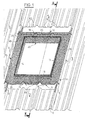
- Figure 1 shows the adaptation of the device on a roof formed by ribbed panels 1, 2, 3, 5 which surrounds an opening.
- the device and the two upper 5 and lower 2 panels are shown offset relative to each other. It is easily understood that, once the installation is complete, the lower side 11 is above the panel 2, and the panel 5 is above the upper side 12.
- the device comprises a rigid frame 20 with walls perpendicular to the mean plane of the roof, externally coated with sheets 33, 34, 35 and 36 of prepainted aluminum.
- the two sheets 34 and 36 forming the lateral sides 13 and 14, are folded to form the ribs 15 and 16 so as to match the profile of the ribs of the roofing panels, and cover the ribs 6 and 7 located at the edges of the opening 4.
- a strip of mastic joint 17 is interposed between the ribs 15 and 16 of the lateral sides 13 and 14 and the ribs 6 and 7 of the panels, before fixing by screwing by means of self-tapping screws 49.
- the sheet 35 has a flat part forming the upper side 12 in the same plane as the non-ribbed parts 13 ′ and 14 ′ of the lateral sides 13 and 14, and is placed below the edge of the upper panel 5, a profile d seal 18, preformed according to the profile of the roofing panels, being inserted at the overlap.
- the fixing is also ensured by screws 49, in the hollow areas 5a of the panel 5.
- the sheet 33 forming the lower side 11 has a flat face 19, offset in height relative to the side 12, by a distance corresponding to the height of the ribs 6 and 7 of the panels 2.
- this flat face 19 comes to cover the edge of the lower panel 2, and is extended by an edge 21 folded down substantially at a right angle and comprising cutouts 22 in the shapes of the profile of the panel 2, the edge 21 thus being able to precisely match said profile.
- a sealing counter-profile 23 (not visible in FIG. 1) is interposed between the flat face 19 and the edge of the panel 2 which it covers, the fixing being ensured by screws 49 placed only at the ribs of said panel .
- the connections between the four sheets 33, 34, 35 and 36 are provided by folding 24 and 25; folds are always carried out so as not to constitute obstacles to the flow of water.
- folds are always carried out so as not to constitute obstacles to the flow of water.
- heddles 151 and 152 made of galvanized sheet are provided for stiffening the aluminum sheets 35 and 33 in their parts forming the upper 12 and lower 11 sides.
- a sleeping frame 100 constituted by the assembly of tabs of aluminum profiles 101 covers the upper edge of the plywood panels 26 and is fixed to it by screws 102.
- the assembly of the profile elements together is ensured in a conventional manner by brackets 103 and 104.
- the shape of the section of the sections 101 is advantageously that shown in FIG. 2. Even if it may differ slightly from the latter, it preferably comprises at least one first part 105 which covers the plywood panels. 26 and used for fixing the frame 100 on these panels; and a second part 106 comprising a groove 107 designed to receive a seal 108, so that this seal can be continuous around the entire periphery of the frame 100.
- a third part 109 of the profile is advantageously shaped into grooves adapted to receive the assembly brackets 103 and 104, or the hinges 110 of articulation of the opening frame which will be described below.
- the aluminum sheets 33, 34, 35 and 36 have an upper fold at right angles 33 ′ and 35 ′ which comes into contact with the profiles 101 to ensure sealing using a seal 111 between the sleeping frame 100 and said aluminum sheets.
- the opening of the smoke exhaust device is composed of a frame 120 also constituted by the assembly of aluminum profiles 121. These profiles have a groove 122 in which is inserted the translucent panel 123, made of plastic.
- This panel is advantageously made of extruded alveolar polycarbonate, with a triple wall, the alveoli being closed with a silicone sealant 124. Other characteristics or alternative embodiments of these panels will be described later in the following description.
- the translucent panel 123 is held between the upper edge 125 of the groove 122 and a tab 126 of the lower edge 127. The seal is ensured by contact of this tab 126 on the underside of the translucent panel 123. Any infiltration that may occur between the upper edge 125 of the groove and the upper face of the panel 123 are discharged through the orifices 128 formed in the bottom of the groove 122 (arrows F in FIG. 2) and the orifices 129 produced at least on the side located at the lowest allowing evacuation of infiltration or condensate to the outside of the profile. Sufficient play is provided between the bottom 130 of the groove 122 and the edges of the translucent panel to allow the free expansion thereof.
- the profiles constituting the opening frame also comprise a projection 130 'directed downward so as to come to press on the lip of the seal 108 when the device is closed.
- the profiles also include an outer rim 130 ⁇ which is placed, in the closed position, in recovery of the sleeping frame 100, thus completing the sealing of the device.
- the opening frame 120 is articulated on the sleeping frame 100, by means of the hinges 110.
- the locking in the closed position is provided in the usual way in the outlets by a device, not shown, sensitive to heat and allowing the opening of the outlet in the event of a rise in temperature.
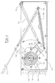
- the opening system comprises, on each side of the outlet, a spiral spring 131 whose central end 132 is immobilized in a groove of an axis 133 itself rigidly linked to a support plate 134 fixed to the frame 20 The other end 135 of the spring 131 engages between two tabs 137 of a plate 136 of rectangular shape mounted free in rotation on the axis 133.
- tension spring 138 One end of a tension spring 138 is fixed in free pivoting on a bolt 139 screwed into the corner of the plate 136 located farthest from the axis 133, and the lowest.
- the other end of the tension spring 138 is mounted in the same way on a bolt 140 fixed to the frame 20 at a point located relative to the hinge hinges 110, further than the axis 133 and slightly lower than that -this.
- a gas spring 141 is mounted by one end 142 on the second angle, distant from the axis 133, from the plate 136, and its other end 143 is fixed, free to rotate, on the opening frame 120.
- the whole of the mechanism is protected by a sheet metal casing 144.
- the dimensioning and positioning of the various elements of the opening system are determined so as to facilitate rapid opening of the outlet, and to ensure the greatest possible angular opening, while guaranteeing an opening force sufficient to overcome the forces created by the dead weight of the opening and possibly by the snow covering it or by the wind.
- the opening system is such that, when the smoke outlet is closed, the plate 136 is directed at about 45 ° downwards, the spiral spring then being compressed (or in tension, depending on the direction of assembly).
- the traction spring 138 is slightly tensioned, and the gas spring 141 is in the end position of the retracted rod.
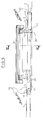
- the frame opening 120 is pushed upwards by the spiral spring 131 and by the gas spring which begins to relax; an additional force is brought by the tension spring 138, until the axis 133 and the two fixings 139 and 140 of the spring 138 are aligned. Beyond this position, the opening continues under the combined thrust of the spiral spring and the gas spring to the maximum opening position (shown in Figure 3 and, partially in dotted lines, in Figure 4).
- the spring 138 acts as a shock absorber by tending to retain the opening frame and thus gradually slowing down its movement.
- the springs and cylinders are dimensioned according to each case, to provide the kinematics described above, according to the dimensions and the weight or loads of the opening frame.
- one or two launchers 145 are mounted on the chassis 20.
- Each launcher consists of an arm 146 articulated on the chassis 20 similarly to the plate 136 of the mechanism. opening and pushed upwards by a spiral spring, and ends with a ball 147 which comes into direct support on an inner wall of the profiles forming the opening frame 120.
- This or these launchers being mounted even further from the articulation of the '' opening that the main opening mechanism, exert, through the spiral spring which equips them, thanks to a reduced length of their rod, a significant opening torque at the very beginning of it, thus greatly facilitating the movement start.
- FIGS. 5 et seq. Show another variant of the invention intended to ensure only the lighting in which the translucent panel is fixed, and tightly connected to the frame 20.
- the device conforms to what has been described above for the first variant, with regard to the connection to the roof and to the construction of the chassis 20. It will however be noted that the coating of the interior of the chassis is here slightly amended.
- the lower part 29 of the sheet 27 extends parallel to the upper 12 or lateral sides 13 and 14 (see FIG. 5 and 6) with the interposition of a layer of rigid insulating material 31.
- the lower part 30 of the sheet 28 corresponding to the lower side 19 is folded up a second time to form a fold 32.
- This arrangement is in particular provided to facilitate the positioning of the device in the opening of the roof, the upper side 12 being able to be slid under the panel upper 5, and the lower side 11 can be applied to the lower panel 2, the fold 32 not constituting discomfort, and even possibly being able to constitute a guide during the introduction of the chassis into the opening of the roof.
- the inner aluminum sheets 27 and 28, and the outer sheets 33, 34, 35 and 36 are not in contact, and therefore do not create a thermal bridge; the sheets 35 and 33 are bent along a rounded radius to facilitate flows.
- FIG. 6 On the right-hand side of FIG. 6 and on FIG. 7 is shown a variant of the invention suitable for insulating roofs.
- the panels 26 of the chassis 20 extend downwards by a distance corresponding to the thickness of the layer of insulating material 31 ′ which is provided to correspond to the thickness of the insulation in place under the roof. .
- a translucent panel 51 of plastic material of the triple-walled cellular polycarbonate type is fitted to the frame 20 in order to seal the opening in a sealed manner, while allowing a maximum of natural light to pass through.
- the triple-walled alveolar polycarbonate is remarkable for its lightness, its good coefficient of thermal insulation, its resistance to thermal and mechanical shocks, and good preservation of these characteristics during aging.
- this material is already known, it is simply recalled that it is formed from three parallel sheets 51 a, 51 b, 51 c spaced apart and connected by longitudinal ribs 51 d and 51 e which define cells 51 f between them.
- the translucent panel is mounted in a frame 52 made of aluminum profiles which fits on the upper edge of the frame 20.
- the aluminum profile 52 ′ has a preferred section such as that shown in FIG. 9. It has in particular an upper tongue 53, directed towards the inside of the frame and under which the edge of the translucent panel 51 is slipped.
- the upper sheet 51a of the panel is in contact with the edge of this tongue, while the lower sheet presses on a seal 54 housed in a recess 55 of the profile 52.
- a play is reserved on the entire periphery of the panel between the latter and the vertical part 56, linked to the tongue 53 of the profile, so as to allow the panel to expand freely.
- holes 57 are made in the profile located on the lower side of the device to allow the evacuation of any condensate, or infiltration between the upper face of the translucent panel and the tongue 53.
- an angle 58 is glued by one of its wings 58 a under the edge of the upper sheet 51 a.
- the other wing 58 b of the angle iron extends downwards over the entire thickness of the panel 51, is pressed against the edge of the panel and closes the cells in a non-leaktight manner, however.
- This system allows the circulation of air and the evacuation of condensates which can be created in the alveoli, but on the other hand limits the penetration and proliferation of microorganisms or insects in it.
- the profile 52 also comprises on each side of the recess 55 receiving the joint 54, two walls 59 and 60 perpendicular to the plane of the panel, and forming with the bottom of the recess 55 a rib in the shape of an inverted U which covers the upper edge of the frame 20. Between the wall 59 located towards the outside of the frame 52 and the aluminum sheets covering the outside of the frame is interposed a seal 62 ensuring the seal between frame and frame.
- the frame is fixed to the frame by screws 63 passing through the wall 60 and screwed from the inside into the panels 26 of the frame 20.
- the frame profiles are cut at the tab and assembled by self-tapping screws 64 crossing a profile and axially screwed in grooves 65 of circular section three in number made respectively on each side of the recess 55, and downwards. the wall 59.
- the profile 52 ′ forming the frame 52.
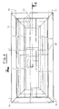
- the profile 52 ⁇ is here rotated by 90 ° so as to present the wall 60 upwards.
- This wall has a recess 66 similar to the recess 55 in which a seal is placed, and it is placed in contact with the underside of the translucent panel 51.
- This arrangement is particularly intended for lighting devices having a large surface, the additional profile is placed in an intermediate position to support the panel 51, for example towards its middle, and prevent it from sagging.
- This intermediate section is fixed in a similar manner to that described above for assembling the frame 52, by screws 67 passing through the frame and screwed into the grooves 65 of the section.
- the invention is not limited to the two variants described above by way of example.
- the device according to the invention is not reserved for roofs or walls formed from ribbed panels, but can also be used on traditional roofs such as tiles, slates, etc.
- some of the characteristics described above as being specific to each of the variants can be combined with one another.
- the sealing mode between translucent panel and frame of a variant can be used in the other, as well as the method of assembling the profiles together.
Landscapes
- Engineering & Computer Science (AREA)
- Architecture (AREA)
- Civil Engineering (AREA)
- Structural Engineering (AREA)
- Chemical & Material Sciences (AREA)
- Combustion & Propulsion (AREA)
- Mechanical Engineering (AREA)
- General Engineering & Computer Science (AREA)
- Building Environments (AREA)
Applications Claiming Priority (2)
| Application Number | Priority Date | Filing Date | Title |
|---|---|---|---|
| FR8717363 | 1987-12-07 | ||
| FR8717363A FR2624161B1 (fr) | 1987-12-07 | 1987-12-07 | Dispositifs d'eclairage et/ou d'aeration ou ventilation destines a etre places en paroi des batiments |
Publications (1)
| Publication Number | Publication Date |
|---|---|
| EP0320407A1 true EP0320407A1 (de) | 1989-06-14 |
Family
ID=9357808
Family Applications (1)
| Application Number | Title | Priority Date | Filing Date |
|---|---|---|---|
| EP88403148A Withdrawn EP0320407A1 (de) | 1987-12-07 | 1988-12-05 | Lüftungs- oder Beleuchtungsvorrichtungen, die an einer Gebäudewand installiert werden können |
Country Status (2)
| Country | Link |
|---|---|
| EP (1) | EP0320407A1 (de) |
| FR (1) | FR2624161B1 (de) |
Cited By (8)
| Publication number | Priority date | Publication date | Assignee | Title |
|---|---|---|---|---|
| DE9307487U1 (de) * | 1993-05-17 | 1993-09-02 | Schlichting, Rolf, 80801 München | Rauch- und Wärmeabzugskuppel mit Dach-Ein- und Ausstieg |
| EP0663489A1 (de) * | 1994-01-07 | 1995-07-19 | E.M.B. Metallbau und Brandschutztechnik GmbH | Lüftungsvorrichtung für Dachöffnungen |
| FR2737235A1 (fr) * | 1995-07-28 | 1997-01-31 | Filclair Sa | Lanterneau d'aeration continu pour batiments d'elevage a couverture isolante souple |
| FR2842230A1 (fr) * | 2002-07-10 | 2004-01-16 | Jean Claude Joly | Lanterneau de toiture equipe d'un dispositif de manoeuvre |
| US20150315793A1 (en) * | 2014-05-05 | 2015-11-05 | Nachman Deutsch | Skylight With Manual Closing Feature |
| GB2584459A (en) * | 2019-06-04 | 2020-12-09 | Leslie Collinson Mark | Scaffolding equipment |
| EP4006254A1 (de) * | 2020-11-27 | 2022-06-01 | VKR Holding A/S | Dachfenster umfassend einen flügel mit äusserem wetterschutzschild |
| WO2024205787A1 (en) * | 2023-03-27 | 2024-10-03 | Siemens Industry, Inc. | Actuator device having power spring retention |
Families Citing this family (1)
| Publication number | Priority date | Publication date | Assignee | Title |
|---|---|---|---|---|
| FR2654133A1 (fr) * | 1989-11-03 | 1991-05-10 | Safiza | Ensemble d'eclairage et/ou de ventilation d'un local couvert comportant une fenetre de toit associee a une fenetre de cloison. |
Citations (16)
| Publication number | Priority date | Publication date | Assignee | Title |
|---|---|---|---|---|
| US3251158A (en) * | 1963-06-17 | 1966-05-17 | Plastic Products Of Texas Inc | Automatic roof vent |
| FR2041516A5 (de) * | 1969-04-28 | 1971-01-29 | Boussois Souchon Neuvesel Sa | |
| FR2112328A1 (de) * | 1970-10-22 | 1972-06-16 | Janssen Leopold | |
| FR2267433A1 (en) * | 1974-04-11 | 1975-11-07 | Eternit Ind Sa | Sealing collar for chimney stack through roof - has upper and lower units connected by units at side of stack |
| FR2386970A7 (fr) * | 1977-04-09 | 1978-11-03 | Frank Gmbh Wilh | Abattant de chassis a tabatiere d'habitation |
| FR2390074A7 (en) * | 1977-05-03 | 1978-12-01 | Frank Gmbh Wilh | Skylight with hinged window - has sealing lip accommodated in groove without touching when open for ventilation |
| US4193237A (en) * | 1978-06-07 | 1980-03-18 | Imperial Glass Structure | Skylight structure |
| FR2542360A1 (fr) * | 1983-03-11 | 1984-09-14 | Alcaud Sa | Dispositif de trappe mobile notamment pour le desenfumage |
| DE3317102A1 (de) * | 1983-05-10 | 1984-11-15 | Ulrich 4970 Bad Oeynhausen Kreft | Lichtelement |
| EP0129357A2 (de) * | 1983-06-10 | 1984-12-27 | Williaam Cox Limited | Dachoberlicht |
| DE3329901A1 (de) * | 1983-08-18 | 1985-03-07 | Ulrich 4970 Bad Oeynhausen Kreft | Aufsatzkranz fuer eine lichtkuppel |
| US4571897A (en) * | 1983-07-21 | 1986-02-25 | Fred Kerr | Apparatus for mounting sheet material and mounting assembly and structural surface formed therewith |
| US4587776A (en) * | 1983-02-15 | 1986-05-13 | Brelan S.A. | Roofing structure |
| DE8601903U1 (de) * | 1986-01-25 | 1986-06-05 | Colt International Gmbh, 4190 Kleve | Belichtungsvorrichtung |
| DE8610217U1 (de) * | 1986-04-15 | 1986-06-26 | Indu-Light GmbH, 7209 Deilingen | Profilsatz aus stranggepreßten Leichtmetallprofilen zur Herstellung von Oberlichtern, Oberlichtbändern, Lüftungs- bzw. Rauchabzugsklappen |
| GB2169326A (en) * | 1985-01-09 | 1986-07-09 | Friedrich Kaspers | Structural assembly comprising panel member and support |
-
1987
- 1987-12-07 FR FR8717363A patent/FR2624161B1/fr not_active Expired - Fee Related
-
1988
- 1988-12-05 EP EP88403148A patent/EP0320407A1/de not_active Withdrawn
Patent Citations (16)
| Publication number | Priority date | Publication date | Assignee | Title |
|---|---|---|---|---|
| US3251158A (en) * | 1963-06-17 | 1966-05-17 | Plastic Products Of Texas Inc | Automatic roof vent |
| FR2041516A5 (de) * | 1969-04-28 | 1971-01-29 | Boussois Souchon Neuvesel Sa | |
| FR2112328A1 (de) * | 1970-10-22 | 1972-06-16 | Janssen Leopold | |
| FR2267433A1 (en) * | 1974-04-11 | 1975-11-07 | Eternit Ind Sa | Sealing collar for chimney stack through roof - has upper and lower units connected by units at side of stack |
| FR2386970A7 (fr) * | 1977-04-09 | 1978-11-03 | Frank Gmbh Wilh | Abattant de chassis a tabatiere d'habitation |
| FR2390074A7 (en) * | 1977-05-03 | 1978-12-01 | Frank Gmbh Wilh | Skylight with hinged window - has sealing lip accommodated in groove without touching when open for ventilation |
| US4193237A (en) * | 1978-06-07 | 1980-03-18 | Imperial Glass Structure | Skylight structure |
| US4587776A (en) * | 1983-02-15 | 1986-05-13 | Brelan S.A. | Roofing structure |
| FR2542360A1 (fr) * | 1983-03-11 | 1984-09-14 | Alcaud Sa | Dispositif de trappe mobile notamment pour le desenfumage |
| DE3317102A1 (de) * | 1983-05-10 | 1984-11-15 | Ulrich 4970 Bad Oeynhausen Kreft | Lichtelement |
| EP0129357A2 (de) * | 1983-06-10 | 1984-12-27 | Williaam Cox Limited | Dachoberlicht |
| US4571897A (en) * | 1983-07-21 | 1986-02-25 | Fred Kerr | Apparatus for mounting sheet material and mounting assembly and structural surface formed therewith |
| DE3329901A1 (de) * | 1983-08-18 | 1985-03-07 | Ulrich 4970 Bad Oeynhausen Kreft | Aufsatzkranz fuer eine lichtkuppel |
| GB2169326A (en) * | 1985-01-09 | 1986-07-09 | Friedrich Kaspers | Structural assembly comprising panel member and support |
| DE8601903U1 (de) * | 1986-01-25 | 1986-06-05 | Colt International Gmbh, 4190 Kleve | Belichtungsvorrichtung |
| DE8610217U1 (de) * | 1986-04-15 | 1986-06-26 | Indu-Light GmbH, 7209 Deilingen | Profilsatz aus stranggepreßten Leichtmetallprofilen zur Herstellung von Oberlichtern, Oberlichtbändern, Lüftungs- bzw. Rauchabzugsklappen |
Cited By (13)
| Publication number | Priority date | Publication date | Assignee | Title |
|---|---|---|---|---|
| DE9307487U1 (de) * | 1993-05-17 | 1993-09-02 | Schlichting, Rolf, 80801 München | Rauch- und Wärmeabzugskuppel mit Dach-Ein- und Ausstieg |
| EP0663489A1 (de) * | 1994-01-07 | 1995-07-19 | E.M.B. Metallbau und Brandschutztechnik GmbH | Lüftungsvorrichtung für Dachöffnungen |
| FR2737235A1 (fr) * | 1995-07-28 | 1997-01-31 | Filclair Sa | Lanterneau d'aeration continu pour batiments d'elevage a couverture isolante souple |
| FR2842230A1 (fr) * | 2002-07-10 | 2004-01-16 | Jean Claude Joly | Lanterneau de toiture equipe d'un dispositif de manoeuvre |
| US20190169850A1 (en) * | 2014-05-05 | 2019-06-06 | Nachman Deutsch | Skylight With Manual Closing Feature |
| US10196822B2 (en) * | 2014-05-05 | 2019-02-05 | Nachman Deutsch | Skylight with manual closing feature |
| US20150315793A1 (en) * | 2014-05-05 | 2015-11-05 | Nachman Deutsch | Skylight With Manual Closing Feature |
| US10900233B2 (en) * | 2014-05-05 | 2021-01-26 | Nachman Deutsch | Skylight with manual closing feature |
| GB2584459A (en) * | 2019-06-04 | 2020-12-09 | Leslie Collinson Mark | Scaffolding equipment |
| GB2584459B (en) * | 2019-06-04 | 2023-09-13 | Leslie Collinson Mark | Scaffolding equipment |
| EP4006254A1 (de) * | 2020-11-27 | 2022-06-01 | VKR Holding A/S | Dachfenster umfassend einen flügel mit äusserem wetterschutzschild |
| WO2024205787A1 (en) * | 2023-03-27 | 2024-10-03 | Siemens Industry, Inc. | Actuator device having power spring retention |
| US12253067B2 (en) | 2023-03-27 | 2025-03-18 | Siemens Industry, Inc. | Actuator device having power spring retention |
Also Published As
| Publication number | Publication date |
|---|---|
| FR2624161A1 (fr) | 1989-06-09 |
| FR2624161B1 (fr) | 1992-09-18 |
Similar Documents
| Publication | Publication Date | Title |
|---|---|---|
| EP3115525B1 (de) | Verstellbare und isolierende blende für eine sonnenschutzanlage | |
| FR2934616A1 (fr) | Structure de toiture constituee de chevrons paralleles munis de feuillures laterales pour la reception de panneaux de remplissage. | |
| EP0884444B1 (de) | Eingangstür für ein Lokal | |
| FR2624161A1 (fr) | Dispositifs d'eclairage et/ou d'aeration ou ventilation destines a etre places en paroi des batiments | |
| EP0128830B1 (de) | Fertigbauteile und ihre Einzelteile | |
| FR3028539A1 (fr) | Lame orientable pour toiture exterieure et un dispositif de toiture exterieure muni desdites lames | |
| EP0320406A1 (de) | Lüftungs- oder Beleuchtungsvorrichtung zur Installation an einer Gebäudewand | |
| EP2103756A2 (de) | Sonnenschutzstruktur | |
| FR2690474A1 (fr) | Revêtement isolant, notamment pour toiture de véranda. | |
| FR2655676A1 (fr) | Toiture isolante a chevrons metalliques. | |
| FR2861410A1 (fr) | Perfectionnement aux toitures de verandas ou de verrieres | |
| FR2590611A1 (fr) | Trappe de toiture a armature isolee thermiquement. | |
| FR2775710A1 (fr) | Cassette polycarbonate pour couverture ou paroi | |
| FR2981115A1 (fr) | Element de coffrage pour un volet roulant, destine a etre pose au niveau de la traverse haute d'un dormant rapporte au sein d'une baie de batiment | |
| EP0041057B1 (de) | Kontinuierliches zwei- oder vierschaliges Belichtungselement | |
| FR2705985A1 (fr) | Système d'éclairage zénithal destiné à être disposé dans une ouverture ménagée dans une toiture. | |
| FR2615225A1 (fr) | Dispositif monte sur un toit pour evacuer la fumee et la chaleur | |
| EP0085632A1 (de) | Dachfenster | |
| FR2570403A1 (fr) | Structure de batiments incorporant des elements, porteurs notamment, en tole galvanisee pliee | |
| FR2598743A1 (fr) | Nouveau dispositif d'huisserie. | |
| BE401171A (de) | ||
| BE1009694A6 (fr) | Agencement de profiles en particulier dans un chassis, et profile de vantail adhoc. | |
| EP1991752B1 (de) | Anordnung aus einer mehrfachverglasungseinheit und einem profil sowie profil für eine verglasungseinheit | |
| FR2732387A1 (fr) | Toiture de veranda | |
| EP0155243A2 (de) | Gruppe von Elementen zum Herstellen leichter Bedachungen, insbesondere von Verandas |
Legal Events
| Date | Code | Title | Description |
|---|---|---|---|
| PUAI | Public reference made under article 153(3) epc to a published international application that has entered the european phase |
Free format text: ORIGINAL CODE: 0009012 |
|
| AK | Designated contracting states |
Kind code of ref document: A1 Designated state(s): BE DE ES GB IT LU |
|
| 17P | Request for examination filed |
Effective date: 19891220 |
|
| 17Q | First examination report despatched |
Effective date: 19910306 |
|
| STAA | Information on the status of an ep patent application or granted ep patent |
Free format text: STATUS: THE APPLICATION IS DEEMED TO BE WITHDRAWN |
|
| 18D | Application deemed to be withdrawn |
Effective date: 19920428 |