EP0320596A1 - Système pour détecter la position avec circuit de subdivision - Google Patents
Système pour détecter la position avec circuit de subdivision Download PDFInfo
- Publication number
- EP0320596A1 EP0320596A1 EP88117227A EP88117227A EP0320596A1 EP 0320596 A1 EP0320596 A1 EP 0320596A1 EP 88117227 A EP88117227 A EP 88117227A EP 88117227 A EP88117227 A EP 88117227A EP 0320596 A1 EP0320596 A1 EP 0320596A1
- Authority
- EP
- European Patent Office
- Prior art keywords
- signals
- measuring device
- analog
- position measuring
- trigger
- Prior art date
- Legal status (The legal status is an assumption and is not a legal conclusion. Google has not performed a legal analysis and makes no representation as to the accuracy of the status listed.)
- Granted
Links
- 238000001514 detection method Methods 0.000 title 1
- 238000005070 sampling Methods 0.000 claims description 22
- 238000011156 evaluation Methods 0.000 claims description 14
- 230000015654 memory Effects 0.000 claims description 14
- 108020001077 Anthranilate Phosphoribosyltransferase Proteins 0.000 claims description 13
- 238000012935 Averaging Methods 0.000 claims 2
- 230000006870 function Effects 0.000 claims 2
- 230000001419 dependent effect Effects 0.000 claims 1
- 230000000737 periodic effect Effects 0.000 claims 1
- 238000010586 diagram Methods 0.000 description 12
- 230000003750 conditioning effect Effects 0.000 description 3
- 238000006243 chemical reaction Methods 0.000 description 2
- 230000001960 triggered effect Effects 0.000 description 2
- 230000008878 coupling Effects 0.000 description 1
- 238000010168 coupling process Methods 0.000 description 1
- 238000005859 coupling reaction Methods 0.000 description 1
- 238000006073 displacement reaction Methods 0.000 description 1
- 230000000694 effects Effects 0.000 description 1
- JLJNENVYAVKECZ-HRXVJLLUSA-N eoxin E4 Chemical compound CCCCC[C@H](O)[C@H](SC[C@H](N)C(O)=O)\C=C\C=C\C=C/C\C=C/CCCC(O)=O JLJNENVYAVKECZ-HRXVJLLUSA-N 0.000 description 1
- 230000003203 everyday effect Effects 0.000 description 1
- 238000000034 method Methods 0.000 description 1
- 230000010363 phase shift Effects 0.000 description 1
Images


Classifications
-
- H—ELECTRICITY
- H03—ELECTRONIC CIRCUITRY
- H03M—CODING; DECODING; CODE CONVERSION IN GENERAL
- H03M1/00—Analogue/digital conversion; Digital/analogue conversion
- H03M1/12—Analogue/digital converters
- H03M1/20—Increasing resolution using an n bit system to obtain n + m bits
- H03M1/202—Increasing resolution using an n bit system to obtain n + m bits by interpolation
- H03M1/203—Increasing resolution using an n bit system to obtain n + m bits by interpolation using an analogue interpolation circuit
-
- G—PHYSICS
- G01—MEASURING; TESTING
- G01D—MEASURING NOT SPECIALLY ADAPTED FOR A SPECIFIC VARIABLE; ARRANGEMENTS FOR MEASURING TWO OR MORE VARIABLES NOT COVERED IN A SINGLE OTHER SUBCLASS; TARIFF METERING APPARATUS; MEASURING OR TESTING NOT OTHERWISE PROVIDED FOR
- G01D5/00—Mechanical means for transferring the output of a sensing member; Means for converting the output of a sensing member to another variable where the form or nature of the sensing member does not constrain the means for converting; Transducers not specially adapted for a specific variable
- G01D5/12—Mechanical means for transferring the output of a sensing member; Means for converting the output of a sensing member to another variable where the form or nature of the sensing member does not constrain the means for converting; Transducers not specially adapted for a specific variable using electric or magnetic means
- G01D5/244—Mechanical means for transferring the output of a sensing member; Means for converting the output of a sensing member to another variable where the form or nature of the sensing member does not constrain the means for converting; Transducers not specially adapted for a specific variable using electric or magnetic means influencing characteristics of pulses or pulse trains; generating pulses or pulse trains
- G01D5/24404—Interpolation using high frequency signals
-
- H—ELECTRICITY
- H03—ELECTRONIC CIRCUITRY
- H03M—CODING; DECODING; CODE CONVERSION IN GENERAL
- H03M1/00—Analogue/digital conversion; Digital/analogue conversion
- H03M1/12—Analogue/digital converters
- H03M1/22—Analogue/digital converters pattern-reading type
- H03M1/24—Analogue/digital converters pattern-reading type using relatively movable reader and disc or strip
- H03M1/28—Analogue/digital converters pattern-reading type using relatively movable reader and disc or strip with non-weighted coding
- H03M1/30—Analogue/digital converters pattern-reading type using relatively movable reader and disc or strip with non-weighted coding incremental
- H03M1/303—Circuits or methods for processing the quadrature signals
Definitions
- the invention relates to a position measuring device according to the preamble of claim 1.
- incremental measuring systems deliver pulses, the number of which represents a measure of the linear displacement or the angle of rotation. These pulses are summed up in an electronic up / down counter as path elements and the measured value is displayed numerically.
- the resolution of incremental position measuring devices is initially only 1/4 of the division period, since two mutually phase-shifted signals U1 and U2, which have four zero crossings for generating counting pulses, are generated by two photodetectors of the scanning unit which are offset by 90 ° to one another. Do they own Both signals have a sufficiently good sine shape, they can be electrically interpolated in different ways between the zero crossings.
- CH-PS 407 569 may be mentioned for the example below.
- the invention is therefore based on the object of improving a position measuring device of the type mentioned at the outset in such a way that the circuitry does not increase in proportion to the division factor.
- the particular advantages are that the switching modules can be used several times, so that a considerably smaller number of triggers is sufficient.
- the basic circuit diagram from FIG. 1 shows a position measuring device M which has a measuring standard 1 and a scanning device 2.
- the material measure 1 and the scanning device 2 are each attached to one of two machine components, not specified, whose relative movement is to be measured. With relative movements of the machine components, the scanning device 2 generates analog scanning signals U1, U2, which are approximately sinusoidal, by scanning the material measure 1 in a known manner. To detect the direction of movement, the scanning signals U1, U2 are 90 ° out of phase with one another. Terms such as sine signals and cosine signals or 0 ° and 90 ° signals have therefore also become established in everyday language.
- the scanning signals U1, U2 are fed into an analog signal processing circuit A. There, a signal period P of the scanning signals U1, U2 is broken down into a number of sectors P1, P2, P3, P4. The number of sectors Pn depends on the desired one Degree of subdivision and the circuit components that are subordinate to the analog signal conditioning circuit A. The sectors P1, P2, P3, P4 are limited by their associated edge signals.
- each sector comprises a range of ⁇ / 2, so that one can speak of quadrants, which thus represent a special form of sector division.
- a switching module 3 which is controlled by a control circuit 4, is connected both to the analog signal conditioning circuit A and to a comparator T. At least one trigger module is located in the comparator T. However, since the analog signals U1, U2 are to be subdivided as high as possible, in practice several trigger modules will be implemented as trigger groups in the comparator T. These cases will be discussed with reference to the following figures.
- the switching module 3 switches the comparator T in a predeterminable sequence to the individual sectors P1, P2, P3, P4.
- the signals of the individual sectors P1, P2, P3, P4 are thus triggered in succession by the comparator T, so that square wave sequences of the desired frequency are present at the output of the comparator T, which are also phase-shifted from one another again.
- FIG. 2 shows a block diagram in which a comparator T2 consists of two triggers T12 and T22.
- a switching module 32 is formed by two so-called analog multiplexers 312 and 322.
- a Control circuit 42 has evaluation logic 412, a clocked up-down counter 422 and a converter module 432, by means of which the control signals for switching the analog multiplexers 312 and 322 are obtained from the count of the up-down counter 422.
- the first group of analog signals to be triggered, which were formed from the scanning signal U1, is applied to the first analog multiplexer 312; the second group of analog signals formed from the scanning signal U2 is applied to the second analog multiplexer 322.
- the example shows how the analog signals are distributed to the analog multiplexers 312 and 322.
- Each analog multiplexer 312 and 322 has an output to which a trigger T12 and T22 is connected.
- the two triggers T12 and T22 are always connected to two adjacent input signals, the trigger T12 always being coupled to the input signal which has the smaller phase shift.
- the position of the analog multiplexers 312, 322 is tracked to the zero crossing of the input signals with the aid of the moving up-down counter 422.
- the two triggers T12, T22 deliver states 0 and 1 outside the zero crossings of the 0 ° signal. If trigger T12 changes the state, this means a backward movement.
- the up-down counter 422 jumps back one step. If trigger T22 changes state, a forward step must be carried out.
- the 0 ° and 90 ° rectangular output signals are obtained from the counter reading.
- the division period P of the scanning signals U1, U2 is broken down into sectors in the analog signal processing circuit A3 in the manner described above.
- the edge signals of a sector Pi are each switched to one of the trigger groups T13 or T23, which divides the sector Pi in question and detects the zero crossings.
- the coupling of the respective sector edge signals to the relevant trigger group T13 or T23 takes place by means of an analog switch module 33.
- the circuit EXE3 uses two trigger groups T13 and T23 which are alternately forward-looking to the next current sector Pi + 1.
- the assignment of sector Pi and trigger group T13 or T23 depends on the position of the switches in the analog switch module 33, that of a control switch device 43 receives the switching commands.
- the control circuit 43 contains evaluation logic 413, a clocked up-down counter 423 and a converter module 433, by means of which the control signals for switching over the analog switching component 33 are obtained from the counter reading of the up-down counter 423.
- the up-down counter 423 must be carried along exactly, since it in turn ensures that the correct trigger group Ti is connected to the correct sector Pi via the analog switching module 33.
- the up-down counter 423 is carried along by the release of a forward pulse or by the release of a downward pulse.
- the decision as to whether and which release should take place is taken from a table that is stored in the evaluation logic 413. This table has as input information the status of the up / down counter 423 and the status of the triggers of the current trigger group T13 or T23.
- the up-down counter 423 At a certain level of the up-down counter 423, there is only one valid status image of the trigger groups T13, T23 for a forward pulse and only one status image for a downward pulse.
- the up / down counter 423 is enabled in one direction or the other. If the up / down counter 423 has carried out this counting step, the input information of the decision table also changes and the release disappears again.
- the table can be implemented as a memory block. To the forward-backward to synchronize counter 423 at the start, it is set to zero when going through a complete division period.
- control signals for the control of an analog switching component 34 are supplied by a control circuit 44, which has an evaluation logic 414, a further trigger group T34 and a converter component 424.
- the comparator T4 can contain one or more trigger groups T14, T24.
- the explanations below relate to two trigger groups T14, T24.
- the phase-shifted signals U1, U2 of a division period P are broken down again into sectors P1 to Pn.
- the edge signals of a sector Pi are each connected to a trigger group T14 or T24, which divides the sector Pi and detects the zero crossings.
- the sector edge signals and the trigger group T14 or T24 are connected with the analog switching module 34.
- the circuit EXE4 uses two switchable trigger groups T14 to T24. They are alternately, looking ahead to the next current sector Pi + 1.
- the position of the analog switch module 34 is determined by the output signals of the third trigger group T34.
- This trigger group T34 is connected to the phase-shifted input signals U1, U2, -U1 and is not switched over.
- the switchable trigger groups T14, T24 are each assigned to certain sectors Pi. If the input signal U1, U2 coming from the position measuring device M has passed through the center of the sector Pi, the trigger group T14 or T24 that is not currently being used is switched over. This is placed on the Pi + 1 sector, which is passed through next while maintaining the direction of movement. The sector center is recognized by the rigid trigger group T34. The output signals of the trigger groups T14, T24, T34 are fed to an evaluation logic 414.
- the evaluation logic 414 contains a signal lock and a code converter.
- the lock prevents the pulses resulting from the trigger group switchover from having an effect on the output.
- the code converter generates the 0 ° and 90 ° rectangular output signals.
- Sectors P1 to Pn are formed from analog scanning signals U1, U2 in an analog signal processing circuit A5.
- the edge signals of a sector Pi are each connected to a trigger group T15 or T25, which divides the sector Pi and detects the zero crossings.
- the sector edge signals and the trigger group T15 or T25 are connected with an analog switching module 35.
- the circuit EXE5 uses two switchable trigger groups T15 and T25. you will be alternately, looking ahead to the next current sector Pi + 1.
- the position of the analog switch module 35 is determined by the output signals of a further, rigid trigger group T35 and the output signals of the switchable trigger groups T15 and T25.
- the rigid trigger group T35 is permanently connected to the phase-shifted input signals U1, U2.
- the switchable trigger groups T15 or T25 are each assigned to certain sectors Pi or Pi + 1. If the input signal coming from the encoder has passed through the middle of a sector Pi, the trigger gurgle T15 or T25 that is not currently being used is switched over. This is placed on the Pi + 1 sector, which, if the direction of movement is maintained, is followed next. The sector center is recognized by the rigid and switchable triggers T15, T25, T35.
- These trigger output signals are fed to a control circuit 45, which determines the position of the analog switching module 35.
- control circuit 45 contains an evaluation logic 415, a start logic 425 and the third trigger group T35 already mentioned.
- the evaluation logic 415 for generating the square-wave output signals also uses all trigger signals. It consists of a filter for the switching impulses, not described in detail, and a filter if not described in more detail code converter stage for conversion into the 0 ° and 90 ° rectangular output signals.
- the functional principle described requires special start logic 425.
- the invalid switch position is recognized by the fact that the output states of all switchable trigger groups T15 and T25 are at ONE or ZERO.
- FIG. 6 A signal diagram in which one of the scanning signals U1 and its subdivision is shown can be found in FIG. 6.
- a signal period P is broken down into eight sectors P1 to P8 and each sector Pi has been subdivided by one of the two trigger groups T1 or T2, each with five triggers 1 'to 5' and 6 'to 10'. Inverting triggers were required for the trigger modules.
- FIG. 7a shows the two scanning signals U1 and U2, which are 90 ° out of phase with one another.
- the harmonic content of the input voltage can be reduced.
- circuit principle - to use only a few comparators Ti in a subdivision circuit EXE and to switch them alternately to different sectors of the scanning signals U1, U2 - can also be used very advantageously in position measuring devices which have a plurality of sampling points ASI to ASn.
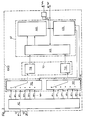
- An angle measuring device has two diametrical sampling points ASI and ASII to compensate for the eccentricity, each sampling point ASI and ASII respectively delivers 0 ° and 90 ° signals U1, U2 and U3, U4. So that the subdivision effort is not doubled due to the double number of sampling points ASI and ASII, the analog sampling signals U1, U2 and U3, U4 are stored in so-called “sample &hold" memories SH1, SH2, SH3 and SH4 cached.
- the temporarily stored analog scanning signals U1, U2 or U3, U4 are each fed to a sampling point ASI or ASII in succession to an analog processing circuit A8, the memories SH1, SH2 or SH3, SH4 being successively sent to the analog signal Processing circuit A8 are switched on, so that the respective memory contents can be transmitted in sampling positions.
- An analog switching module 38 connects a comparator (T8), which can consist of one or more triggers, to the various sectors which, in a similar manner as already described, in the analog signal conditioning circuit A8 from the scanning signals U1, U2 or U3, U4 one sampling point ASI or ASII are formed.
- a comparator T8
- these square-wave signals After triggering the sector signals, which have been subdivided again, these square-wave signals, which are phase-shifted relative to one another, are stored in digital memories L1 and L2.
- the binary values of the sampling point ASI are stored in the digital memory L1 and the binary values of the sampling point ASII are stored in the digital memory L2.
- the memory control circuit A4 ensures that the analog scanning signals U3, U4 of the second sampling point ASII can only be processed in the analog signal processing circuit A8 when the scanning signals U1, U2 of the first sampling point ASI are completely subdivided, digitized and in the associated digital memory L1 are saved.
- the binary values of all sampling points ASI and ASII are formed in an addition stage, which is formed by a full adder V. is added and divided by the number of sampling points, here two.
Landscapes
- Engineering & Computer Science (AREA)
- Theoretical Computer Science (AREA)
- Physics & Mathematics (AREA)
- General Physics & Mathematics (AREA)
- Transmission And Conversion Of Sensor Element Output (AREA)
- Measurement Of Length, Angles, Or The Like Using Electric Or Magnetic Means (AREA)
Applications Claiming Priority (2)
| Application Number | Priority Date | Filing Date | Title |
|---|---|---|---|
| DE3742329A DE3742329C1 (de) | 1987-12-14 | 1987-12-14 | Positionsmesseinrichtung mit Unterteilungsschaltung |
| DE3742329 | 1987-12-14 |
Publications (2)
| Publication Number | Publication Date |
|---|---|
| EP0320596A1 true EP0320596A1 (fr) | 1989-06-21 |
| EP0320596B1 EP0320596B1 (fr) | 1992-05-27 |
Family
ID=6342561
Family Applications (1)
| Application Number | Title | Priority Date | Filing Date |
|---|---|---|---|
| EP88117227A Expired - Lifetime EP0320596B1 (fr) | 1987-12-14 | 1988-10-17 | Système pour détecter la position avec circuit de subdivision |
Country Status (2)
| Country | Link |
|---|---|
| EP (1) | EP0320596B1 (fr) |
| DE (2) | DE3742329C1 (fr) |
Cited By (1)
| Publication number | Priority date | Publication date | Assignee | Title |
|---|---|---|---|---|
| EP0900998A1 (fr) * | 1997-09-05 | 1999-03-10 | Hella KG Hueck & Co. | Capteur inductif de position angulaire |
Families Citing this family (3)
| Publication number | Priority date | Publication date | Assignee | Title |
|---|---|---|---|---|
| DE3929239A1 (de) * | 1989-09-02 | 1991-03-07 | Teldix Gmbh | Ringlaserkreisel |
| DE3939904A1 (de) * | 1989-12-02 | 1991-06-06 | Teldix Gmbh | Ringlaserkreisel |
| DE19831960A1 (de) * | 1998-07-16 | 2000-01-20 | Itt Mfg Enterprises Inc | Wegsensor |
Citations (1)
| Publication number | Priority date | Publication date | Assignee | Title |
|---|---|---|---|---|
| CH407569A (de) * | 1963-12-04 | 1966-02-15 | Contraves Ag | Digitale Auswerteeinrichtung für stetig veränderliche Messgrössensignale |
-
1987
- 1987-12-14 DE DE3742329A patent/DE3742329C1/de not_active Expired
-
1988
- 1988-10-17 DE DE8888117227T patent/DE3871508D1/de not_active Expired - Fee Related
- 1988-10-17 EP EP88117227A patent/EP0320596B1/fr not_active Expired - Lifetime
Patent Citations (1)
| Publication number | Priority date | Publication date | Assignee | Title |
|---|---|---|---|---|
| CH407569A (de) * | 1963-12-04 | 1966-02-15 | Contraves Ag | Digitale Auswerteeinrichtung für stetig veränderliche Messgrössensignale |
Cited By (3)
| Publication number | Priority date | Publication date | Assignee | Title |
|---|---|---|---|---|
| EP0900998A1 (fr) * | 1997-09-05 | 1999-03-10 | Hella KG Hueck & Co. | Capteur inductif de position angulaire |
| US6366078B1 (en) | 1997-09-05 | 2002-04-02 | Hella Kg Hueck & Co. | Inductive angle sensor with a plurality of receiving coils and an evaluation circuit |
| CZ296834B6 (cs) * | 1997-09-05 | 2006-06-14 | Hella Kg Hueck Co. | Induktivní úhlový sensor |
Also Published As
| Publication number | Publication date |
|---|---|
| EP0320596B1 (fr) | 1992-05-27 |
| DE3871508D1 (de) | 1992-07-02 |
| DE3742329C1 (de) | 1989-03-30 |
Similar Documents
| Publication | Publication Date | Title |
|---|---|---|
| DE3105782C2 (de) | Analog-Digitalumsetzer | |
| DE3640672C2 (fr) | ||
| DE3838291C1 (fr) | ||
| EP0085161B1 (fr) | Dispositif digital électrique de mesure de longueurs ou d'angles | |
| DE3231990A1 (de) | Auswerteeinrichtung fuer einen digitalen inkrementalgeber | |
| DE3221982A1 (de) | Optisches inkrementalcodiersystem mit adressierbarem index | |
| EP1606590A1 (fr) | Procede de mesure de position et systeme de mesure de position destines a la multiplication de periodes de signaux | |
| DE3640413C2 (de) | Meßanordnung | |
| DE1945206A1 (de) | Einrichtung zur Interpolation | |
| DE4443898C2 (de) | Positionsmeßverfahren und Positionsmeßeinrichtung | |
| EP0320596B1 (fr) | Système pour détecter la position avec circuit de subdivision | |
| EP3124920B1 (fr) | Dispositif de mesure de position et son procédé de fonctionnement | |
| WO2010034537A2 (fr) | Système et procédé de production d'une impulsion de référence pour un appareil de mesure de position | |
| DE3737720C1 (en) | Position-measuring device having a subdividing circuit | |
| DE3738546C1 (de) | Positionsmesseinrichtung mit Unterteilungsschaltung | |
| DE19502276C2 (de) | Interpolationsverfahren und hochauflösende digitale Interpolationseinrichtung | |
| EP0062698A2 (fr) | Circuit d'évaluation pour un transducteur de vitesse de rotation | |
| DE2361649C3 (de) | Abtastvorrichtung für eine elektrische Kopiersteuerungsvorrichtung | |
| DE3788329T2 (de) | Gerät zum Anzeigen des Wertes einer Variablen. | |
| DE2620969C2 (de) | Digital-Analogwandler bei einem Lagemeßsystem | |
| DE3123002A1 (de) | Verfahren und einrichtung zur drehzahlmessung einer mit einem rotierenden impulsgeber gekuppelten welle | |
| DE2755038B2 (de) | Analogkomparator | |
| DE8915310U1 (de) | Positionsmeßeinrichtung mit Unterteilungsschaltung | |
| DE3513343C2 (fr) | ||
| DE102006029650A1 (de) | Schaltungsanordung und Verfahren zur Kippfehlerermittlung an einer Positionsmesseinrichtung |
Legal Events
| Date | Code | Title | Description |
|---|---|---|---|
| PUAI | Public reference made under article 153(3) epc to a published international application that has entered the european phase |
Free format text: ORIGINAL CODE: 0009012 |
|
| 17P | Request for examination filed |
Effective date: 19881027 |
|
| AK | Designated contracting states |
Kind code of ref document: A1 Designated state(s): AT CH DE ES FR GB IT LI NL SE |
|
| 17Q | First examination report despatched |
Effective date: 19900726 |
|
| RBV | Designated contracting states (corrected) |
Designated state(s): DE FR GB IT |
|
| ITF | It: translation for a ep patent filed | ||
| GRAA | (expected) grant |
Free format text: ORIGINAL CODE: 0009210 |
|
| AK | Designated contracting states |
Kind code of ref document: B1 Designated state(s): DE FR GB IT |
|
| ET | Fr: translation filed | ||
| REF | Corresponds to: |
Ref document number: 3871508 Country of ref document: DE Date of ref document: 19920702 |
|
| GBT | Gb: translation of ep patent filed (gb section 77(6)(a)/1977) | ||
| PLBE | No opposition filed within time limit |
Free format text: ORIGINAL CODE: 0009261 |
|
| STAA | Information on the status of an ep patent application or granted ep patent |
Free format text: STATUS: NO OPPOSITION FILED WITHIN TIME LIMIT |
|
| 26N | No opposition filed | ||
| PGFP | Annual fee paid to national office [announced via postgrant information from national office to epo] |
Ref country code: GB Payment date: 20000915 Year of fee payment: 13 |
|
| PGFP | Annual fee paid to national office [announced via postgrant information from national office to epo] |
Ref country code: DE Payment date: 20001005 Year of fee payment: 13 |
|
| PGFP | Annual fee paid to national office [announced via postgrant information from national office to epo] |
Ref country code: FR Payment date: 20001012 Year of fee payment: 13 |
|
| PG25 | Lapsed in a contracting state [announced via postgrant information from national office to epo] |
Ref country code: GB Free format text: LAPSE BECAUSE OF NON-PAYMENT OF DUE FEES Effective date: 20011017 |
|
| REG | Reference to a national code |
Ref country code: GB Ref legal event code: IF02 |
|
| GBPC | Gb: european patent ceased through non-payment of renewal fee |
Effective date: 20011017 |
|
| PG25 | Lapsed in a contracting state [announced via postgrant information from national office to epo] |
Ref country code: FR Free format text: LAPSE BECAUSE OF NON-PAYMENT OF DUE FEES Effective date: 20020628 |
|
| PG25 | Lapsed in a contracting state [announced via postgrant information from national office to epo] |
Ref country code: DE Free format text: LAPSE BECAUSE OF NON-PAYMENT OF DUE FEES Effective date: 20020702 |
|
| REG | Reference to a national code |
Ref country code: FR Ref legal event code: ST |
|
| PG25 | Lapsed in a contracting state [announced via postgrant information from national office to epo] |
Ref country code: IT Free format text: LAPSE BECAUSE OF NON-PAYMENT OF DUE FEES Effective date: 20051017 |