EP0320598A2 - Procédé d'accord d'un modulateur HF - Google Patents
Procédé d'accord d'un modulateur HF Download PDFInfo
- Publication number
- EP0320598A2 EP0320598A2 EP88117279A EP88117279A EP0320598A2 EP 0320598 A2 EP0320598 A2 EP 0320598A2 EP 88117279 A EP88117279 A EP 88117279A EP 88117279 A EP88117279 A EP 88117279A EP 0320598 A2 EP0320598 A2 EP 0320598A2
- Authority
- EP
- European Patent Office
- Prior art keywords
- channel
- modulator
- tuning
- channels
- tuner
- Prior art date
- Legal status (The legal status is an assumption and is not a legal conclusion. Google has not performed a legal analysis and makes no representation as to the accuracy of the status listed.)
- Granted
Links
Images
Classifications
-
- H—ELECTRICITY
- H03—ELECTRONIC CIRCUITRY
- H03J—TUNING RESONANT CIRCUITS; SELECTING RESONANT CIRCUITS
- H03J1/00—Details of adjusting, driving, indicating, or mechanical control arrangements for resonant circuits in general
- H03J1/0008—Details of adjusting, driving, indicating, or mechanical control arrangements for resonant circuits in general using a central processing unit, e.g. a microprocessor
- H03J1/0091—Details of adjusting, driving, indicating, or mechanical control arrangements for resonant circuits in general using a central processing unit, e.g. a microprocessor provided with means for scanning over a band of frequencies
-
- H—ELECTRICITY
- H03—ELECTRONIC CIRCUITRY
- H03C—MODULATION
- H03C3/00—Angle modulation
- H03C3/02—Details
- H03C3/09—Modifications of modulator for regulating the mean frequency
Definitions
- the invention relates to a method for tuning an RF modulator, which is operated in a video recorder with an automatically tunable tuner and is tuned via a voltage-controlled oscillator.
- the output signal of the voltage-controlled oscillator set to a suitable channel is amplified via the correspondingly tuned and tuned tuner.
- the level of the amplified oscillator signal is evaluated and, depending on this, a control signal is formed which changes the fine tuning of the modulator until the level of the amplified oscillator signal reaches a maximum.
- a control signal is formed which changes the fine tuning of the modulator until the level of the amplified oscillator signal reaches a maximum.
- the disadvantage of this method is in particular that the selection of a suitable channel to which the modulator is to be tuned has to be done manually. Only the subsequent fine tuning runs automatically. Apart from the manual channel selection itself, there is also the disadvantage that the cheapest free channel for the modulator is not always selected.
- the invention has for its object to provide a method of the type specified in the preamble of claim so that a quick and precise modulator tuning is guaranteed, and that the cheapest free channel is always automatically selected for modulator tuning.
- the channel assignment of the receivable transmitters present at the receiving location is determined via the automatically adjustable tuner. Furthermore, a permanently stored tuning range of the modulator is queried channel by channel in order to determine the free channels that are still possible for the channel selection of the modulator. From the channels in question, the one that has the largest channel spacings with regard to the channels occupied at the receiving location is finally selected.
- the tuning range of the modulator (e.g. channels 30 to 40) is advantageously stored in the memory of a microcomputer.
- the channel assignment available at the respective receiving location can e.g. B. determined by a search of the tuner and also stored in the memory of a microcomputer. By comparing the modulator tuning range and the determined channel assignment, the microcomputer can then select the most suitable channel with regard to large channel spacings and thus an optimal signal-to-noise ratio.
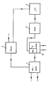
- the block circuit shown shows a modulator 6 to be tuned with a voltage-controlled oscillator 2, the output of which is connected via a signal path 1 to the input of a tuner 3 which is present in the video recorder and is preferably automatically adjustable anyway.
- signal path 1 is designed as a switch with an antenna amplifier, which allows the tuner to be supplied with either the oscillator signal or an antenna signal (received signal) via the antenna amplifier.
- An output of the tuner 3, at which the selectively amplified and preferably rectified input signal can be tapped, is connected to a microcomputer 4 which is also already present in the video recorder and which controls the tuning of the oscillator 2 via a digital-to-analog converter (DAC).
- DAC digital-to-analog converter
- the antenna signal is fed to the tuner 3 via the signal path 1.
- a search run that can be carried out via the tuner can now be used to determine the channel occupancy of the receivable transmitters that is present at the receiving location and that is simultaneously stored in a memory of the microcomputer 4.
- the tuning range of the modulator eg channels 30 to 40
- the microcomputer can select the most suitable free channel with regard to the channel spacing between occupied and free channels and can carry out the corresponding rough tuning of the oscillator 2 via the digital-analog converter 5.
- the antenna or receive signal is separated from tuner 3 and the output signal of oscillator 2 is fed to the tuner in its place.
- the automatically tunable tuner is also tuned to the channel selected for the modulator.
- the method according to the invention now also automatically determines the cheapest free channel.
Landscapes
- Engineering & Computer Science (AREA)
- Computer Hardware Design (AREA)
- Microelectronics & Electronic Packaging (AREA)
- Channel Selection Circuits, Automatic Tuning Circuits (AREA)
- Input Circuits Of Receivers And Coupling Of Receivers And Audio Equipment (AREA)
Applications Claiming Priority (2)
| Application Number | Priority Date | Filing Date | Title |
|---|---|---|---|
| DE19873742654 DE3742654A1 (de) | 1987-04-09 | 1987-12-16 | Verfahren zur abstimmung eines hf-modulators |
| DE3742654 | 1987-12-16 |
Publications (3)
| Publication Number | Publication Date |
|---|---|
| EP0320598A2 true EP0320598A2 (fr) | 1989-06-21 |
| EP0320598A3 EP0320598A3 (en) | 1990-02-28 |
| EP0320598B1 EP0320598B1 (fr) | 1992-12-30 |
Family
ID=6342754
Family Applications (1)
| Application Number | Title | Priority Date | Filing Date |
|---|---|---|---|
| EP88117279A Expired - Lifetime EP0320598B1 (fr) | 1987-12-16 | 1988-10-18 | Procédé d'accord d'un modulateur HF |
Country Status (2)
| Country | Link |
|---|---|
| EP (1) | EP0320598B1 (fr) |
| DE (1) | DE3877169D1 (fr) |
Family Cites Families (3)
| Publication number | Priority date | Publication date | Assignee | Title |
|---|---|---|---|---|
| JPS583672U (ja) * | 1981-07-01 | 1983-01-11 | アルプス電気株式会社 | Rf変調装置 |
| DE3303711C2 (de) * | 1983-02-04 | 1985-01-24 | Deutsche Thomson-Brandt Gmbh, 7730 Villingen-Schwenningen | Abstimmeinheit für Geräte der Nachrichtentechnik |
| DE3711983A1 (de) * | 1987-04-09 | 1988-10-27 | Grundig Emv | Verfahren zur feinabstimmung eines hf-modulators und anordnung zur durchfuehrung des verfahrens |
-
1988
- 1988-10-18 EP EP88117279A patent/EP0320598B1/fr not_active Expired - Lifetime
- 1988-10-18 DE DE8888117279T patent/DE3877169D1/de not_active Expired - Lifetime
Also Published As
| Publication number | Publication date |
|---|---|
| HK1001482A1 (en) | 1998-06-19 |
| EP0320598B1 (fr) | 1992-12-30 |
| EP0320598A3 (en) | 1990-02-28 |
| DE3877169D1 (de) | 1993-02-11 |
Similar Documents
| Publication | Publication Date | Title |
|---|---|---|
| EP0497116B1 (fr) | Récepteur de radiodiffusion avec RDS | |
| DE2442550C2 (de) | Kanalwählsystem | |
| DE2929901C2 (de) | Elektronischer Kanalwähler | |
| EP0531725A2 (fr) | Récepteur à onde ultracourtes à plusieurs antennes | |
| DE2312651A1 (de) | Fernmeldeempfaenger | |
| WO1984003184A1 (fr) | Unite d'accord pour systeme de communication | |
| DE3036351C2 (de) | Abstimmsystem für einen Fernsehempfänger | |
| DE3406150C2 (fr) | ||
| EP0314873A1 (fr) | Dispositif pour l'application automatique de la tension d'accord aux éléments de circuit accordables d'un amplificateur de fréquence intermédiaire d'un récepteur de télévision | |
| DE2836288C2 (de) | Kombi-Tuner | |
| DE3208760C2 (fr) | ||
| DE2333851A1 (de) | Verfahren und anordnungen zur selbsttaetigen nachregelung der mit einer abstimmanordnunggeingestellten oszillatorfrequenz eines ueberlagerungsempfangsteils einer bild und/oder tonwiedergabeanordnung | |
| DE2834231A1 (de) | Verfahren zur selbsttaetigen gleichlaufeinstellung zwischen vor- und oszillatorkreis in einem ueberlagerungsempfaenger und schaltungsanordnung zur durchfuehrung dieses verfahrens | |
| EP0320598B1 (fr) | Procédé d'accord d'un modulateur HF | |
| EP0046835B1 (fr) | Appareil de radiotélécommunication à canaux multiples pour les modes de fonctionnement "intercommunication" et/ou "téléphonie bidirectionnelle alternative" | |
| DE1801703C3 (de) | Empfangseinrichtung mit Suchlaufautomatik | |
| DE3742654A1 (de) | Verfahren zur abstimmung eines hf-modulators | |
| DE3220462C1 (de) | Spektrumanalysator | |
| EP0036086A1 (fr) | Autoradio OTC équipé d'un récepteur en deux parties et de deux chercheurs-émetteurs | |
| DE2607530A1 (de) | Funksende- und/oder -empfangsgeraet mit einer oszillatoren-einrichtung | |
| EP0285926A2 (fr) | Procédé d'accord fin d'un modulateur HF et montage de réalisation du procédé | |
| DE3148085A1 (de) | Mehrstationsempfaenger | |
| DE2758951A1 (de) | Empfangseinrichtung fuer signale des fernsehbereichs | |
| EP0252272B1 (fr) | Récepteur haute fréquence avec indication numérique de la fréquence de réception | |
| DE3317158C2 (fr) |
Legal Events
| Date | Code | Title | Description |
|---|---|---|---|
| PUAI | Public reference made under article 153(3) epc to a published international application that has entered the european phase |
Free format text: ORIGINAL CODE: 0009012 |
|
| AK | Designated contracting states |
Kind code of ref document: A2 Designated state(s): DE FR GB IT |
|
| PUAL | Search report despatched |
Free format text: ORIGINAL CODE: 0009013 |
|
| AK | Designated contracting states |
Kind code of ref document: A3 Designated state(s): DE FR GB IT |
|
| 17P | Request for examination filed |
Effective date: 19900317 |
|
| 17Q | First examination report despatched |
Effective date: 19920429 |
|
| GRAA | (expected) grant |
Free format text: ORIGINAL CODE: 0009210 |
|
| AK | Designated contracting states |
Kind code of ref document: B1 Designated state(s): DE FR GB IT |
|
| GBT | Gb: translation of ep patent filed (gb section 77(6)(a)/1977) |
Effective date: 19930112 |
|
| REF | Corresponds to: |
Ref document number: 3877169 Country of ref document: DE Date of ref document: 19930211 |
|
| ET | Fr: translation filed | ||
| ITF | It: translation for a ep patent filed | ||
| PLBE | No opposition filed within time limit |
Free format text: ORIGINAL CODE: 0009261 |
|
| STAA | Information on the status of an ep patent application or granted ep patent |
Free format text: STATUS: NO OPPOSITION FILED WITHIN TIME LIMIT |
|
| REG | Reference to a national code |
Ref country code: GB Ref legal event code: 746 Effective date: 19931112 |
|
| 26N | No opposition filed | ||
| ITPR | It: changes in ownership of a european patent |
Owner name: OFFERTA DI LICENZA AL PUBBLICO |
|
| REG | Reference to a national code |
Ref country code: FR Ref legal event code: DL |
|
| REG | Reference to a national code |
Ref country code: FR Ref legal event code: CD |
|
| REG | Reference to a national code |
Ref country code: FR Ref legal event code: TP |
|
| REG | Reference to a national code |
Ref country code: GB Ref legal event code: IF02 |
|
| REG | Reference to a national code |
Ref country code: GB Ref legal event code: 732E |
|
| REG | Reference to a national code |
Ref country code: FR Ref legal event code: TP |
|
| PG25 | Lapsed in a contracting state [announced via postgrant information from national office to epo] |
Ref country code: IT Free format text: LAPSE BECAUSE OF NON-PAYMENT OF DUE FEES;WARNING: LAPSES OF ITALIAN PATENTS WITH EFFECTIVE DATE BEFORE 2007 MAY HAVE OCCURRED AT ANY TIME BEFORE 2007. THE CORRECT EFFECTIVE DATE MAY BE DIFFERENT FROM THE ONE RECORDED. Effective date: 20051018 |
|
| PGFP | Annual fee paid to national office [announced via postgrant information from national office to epo] |
Ref country code: DE Payment date: 20071030 Year of fee payment: 20 |
|
| PGFP | Annual fee paid to national office [announced via postgrant information from national office to epo] |
Ref country code: GB Payment date: 20071018 Year of fee payment: 20 |
|
| REG | Reference to a national code |
Ref country code: GB Ref legal event code: PE20 Expiry date: 20081017 |
|
| PGFP | Annual fee paid to national office [announced via postgrant information from national office to epo] |
Ref country code: FR Payment date: 20071031 Year of fee payment: 20 |
|
| PG25 | Lapsed in a contracting state [announced via postgrant information from national office to epo] |
Ref country code: GB Free format text: LAPSE BECAUSE OF EXPIRATION OF PROTECTION Effective date: 20081017 |