EP0320636A2 - Verriegelvorrichtung für äusserliche Universalweiche für Eisenbahnweichen - Google Patents
Verriegelvorrichtung für äusserliche Universalweiche für Eisenbahnweichen Download PDFInfo
- Publication number
- EP0320636A2 EP0320636A2 EP88119115A EP88119115A EP0320636A2 EP 0320636 A2 EP0320636 A2 EP 0320636A2 EP 88119115 A EP88119115 A EP 88119115A EP 88119115 A EP88119115 A EP 88119115A EP 0320636 A2 EP0320636 A2 EP 0320636A2
- Authority
- EP
- European Patent Office
- Prior art keywords
- slide
- lock
- drive
- point
- box
- Prior art date
- Legal status (The legal status is an assumption and is not a legal conclusion. Google has not performed a legal analysis and makes no representation as to the accuracy of the status listed.)
- Granted
Links
Images


Classifications
-
- B—PERFORMING OPERATIONS; TRANSPORTING
- B61—RAILWAYS
- B61L—GUIDING RAILWAY TRAFFIC; ENSURING THE SAFETY OF RAILWAY TRAFFIC
- B61L5/00—Local operating mechanisms for points or track-mounted scotch-blocks; Visible or audible signals; Local operating mechanisms for visible or audible signals
- B61L5/10—Locking mechanisms for points; Means for indicating the setting of points
Definitions
- the invention relates to a universal outer point lock device for switchpoints, particularly on high-speed railways.
- the invention aims to provide a point lock device ensuring a universal control, i.e. adapted to be controlled as desired either by any electric control box and by a manual control device, and having a great operational flexibility, and more particularly it can be substituted for the presently-used key point lock, type FS 44, wherein the point locking is ensured by the possession of a key, and for the presently-used electric point lock, type FS 55, wherein the point locking is ensured by the positioning of electrical contacts.
- the point lock device should be of a sturdy, simple and inexpensive construction, of easy setup, reliable operation, and it should be exempt - as far as possible - from periodical maintenance.
- the point lock device comprises two point locks, associated each with one of the blades of the switchpoints and each comprising a box secured, preferably, to the corresponding stock-rail and containing two slides parallel to each other and slidably guided across the rails, and one of which, so-called lock-slide, is connected to the respective blade and carries a lock member to become locked to the box in the closed position of the blade, while it may be coupled to the other slide, so-called drive-slide, through a coupling device automatically engageable and disengageable as a result of the overlap stroke of the drive-slide with respect to the lock-slide, the drive-slides of the two point locks being connected to each other and to a drive rod, and each drive-slide being provided with a snap lock device to lock said drive-slide to the box at the two end positions thereof, while each drive slide is provided with means for the actuation of the corresponding lock-slide, i.e. for locking it to the box and unlock
- the opened blade or switchrail is stabilized by locking the lock-slide to the drive-slide and by locking said drive-slide to the box, by means of the respective coupling and snap lock devices, while the closed blade is locked by the engagement (to the box) of the lock member which is provided on the lock slide and is carried and held in this position by the respective actuating means for the drive slide, the latter being stabilized by becoming locked to the box by means of the respective snap lock device, whereas the coupling device between the lock-slide and drive-slide is disengaged.
- the drive-slides are moved correspondingly by the drive rod, by first effecting an initial overlap stroke whereby both drive-slides are unlocked from the respective boxes by disengaging the corresponding snap lock devices by overcoming their stabilizing force, while the drive-slide which is associated with the point lock of the closed blade causes the lock member to disengage from the box and, therefore, eliminates the locking of the closed blade, yet without displacing it, coupling together with the lock slide by the respective coupling device on completion of said initial overlap stroke.
- the point lock according to the invention may be constructed of either the trail-open type (by providing no further mechanical lock between the drive-slides and respective boxes), or the permanent not trail-open type (by providing suitable mechanical locks between the drive-slides and respective boxes), or the selective trail-open type (by providing means to be engaged or disengaged at will, e.g. by an electro-magnet or the like, to lock the drive-slides to the respective boxes).
- the point lock device according to the invention may also be provided with any suitable electrical control device which then forms, preferably, an integral portion of each point lock and is housed in a sealed casing, preferably, in a suitable compartment of the box of the respective point lock.
- the boxes of the point lock according to the invention are, preferably, sealed against sand, dust and water.
- the point lock device according to the invention may also be provided with a suitable device designed to compensate for the thermal expansion of the blade and/or with detector or feeler means which issues the command only after detecting the presence and/or consistence of the rail stock whereagainst the blade is matched.
- the outer point lock according to the invention may be actuated by any control means, more particularly, either manually via a corresponding drive box, or electrically via a suitable electrical drive box.
- the two final positions of the point lock device according to the invention are stabilized automatically and regardless of the actuating means, with a force corresponding to the sum of the two forces by which the drive-slides of the two point locks are locked to the corresponding boxes by means of the respective snap-lock devices.
- Said forces may be changed and matched to the specific requirements by regulating the usually elastic means causing the engagement of the snap-lock devices.
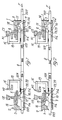
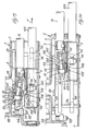
- the point lock device shown in the Figs. 1 to 10 comprises two point locks 1 and 2 associated each with one of the blades or switchrails A1, A2 of a railway switch.
- the two point locks are equal to each other and are disposed in mirror-like opposite positions with respect to the rails.
- the fitting up is effected, preferably, in the inter-sleeper space, between the first and second tip-bearings of the switchpoints.
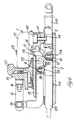
- Each point lock 1, 2 comprises a sealed box 3 which is mounted under the respective stock rail C1, C2 and is secured to the web thereof by means of a bracket 4 and a bolt 5, while the base of the stock rail C1, C2 is secured to the box 3 by means of suitable stirrups 6.
- each point lock 1 Slidably mounted on each other in the box 3 are two slides 7 and 8, namely a lower one, so-called drive-slide 7, and an upper one, so-called lock-slide 8.
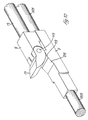
- the drive-slides 7 of the two point locks 1, 2 are connected to each other by means of short inner rods 107 secured thereto and a regulatable link-rod 9.
- the drive-slide 7 of each point lock 1, 2 is secured to a short outer rod 207 by means of which, in the illustrated exemplary embodiment, the drive-slide 7 of one of the point locks 1, 2 (e.g.
- the point lock 1) is connected to the switchpoints operating means, for example, an electrical operating box, while the outer rod 207 of the drive-slide 7 of the other point lock 2 may be connected to the switchpoints indicator signal.
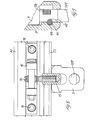
- a snap-lok device adapted to lock the drive-slide 7 to said box 3 with a certain stabilizing force in both the end positions of the switchpoints.
- said snap-lock consists of two conical notches 11a and 11d in the bottom of the box 3 and corrsponding: one (11a) to the closed position of the blade A1, A2 and the other (11d) to the opened position of the blade A1, A2, and of a pointed pin 10 slidably vertically movable in a corresponding seat in the drive-slide 7 and protruding with its conical end from the undersurface of said drive-slide 7.
- Said pin 10 by the action of a pressure spring 12, can engage with its lower conical end, at each of the two end positions of the switchpoints, into the corresponding notch 11a, 11d in the bottom of the box 3, thus locking the drive-slide 7 to said box 3.
- the lock-slide 8 of each point lock 1, 2 is connected to the respective blade A1, A2 by means of an L-shaped bracket 13 which is pivoted through a ball joint 14 to a leg 15 which is secured to the blade by a pair of bolts 16.
- Pivoted at the end of the lock slide 8 is a lock pawl 17 which is freely rotatable about a transverse shaft 117 and co-operates with a recess 18 in the upper wall of the box 3.
- the drive-slide 7 comprises means for actuating said lock pawl 17, consisting - in the embodiment of Figs. 1 to 10 - of two surfaces 119, 219 whereon the lock pawl 17 may rest.
- One of these surfaces (119) is at a higher level and when disposed under the lock pawl 17 it will lift said pawl angularly so as to engage it into the recess 18 (Figs. 6 and 10).
- the other of said rest surfaces (219), however, is at a lower level, either inclined (Figs. 6 and 10) or cradle-shaped (Figs. 1 to 5), and when disposed under the lock pawl 17 it permits a downwards rotation thereof to a position wherein it is disengaged from the recess 18 (Fig. 5).
- a snap-lock device comprising - in the exemplary embodiment of Figs. 1 to 10 - a notch 29 in the upper surface of the drive-slide 7 and a pin 28 vertically slidably movable in a corresponding seat in the lock-slide 8 and protruding with its conical end from the undersurface of said lock-slide 8, as shown particularly in Fig. 6.
- the pin 28 is urged downwards by a pressure spring 39, so that it will engage, with a snap action, into the notch 29 in the drive-slide 7 thereunder, when registering with said notch 29.
- Each point lock comprises an electrical control unit 20 which may be of any suitable construction, known per se , and is housed in a sealed casing 21 arranged on the top of the box 3.
- Said control unit 20 may be activated by a rod 22 which is slidably vertically passed through the top wall of the box 3 and is urged in a direction, e.g. downwards, by a pressure spring 23, as shown particularly in Fig. 7.
- the top end of said rod 22 is provided with a rack 122 meshing with a pinion 24 which actuates the control unit 20.
- the lower end of the rod 22 is also provided with a rack 222 meshing with a pinion 25 rotatably and idly mounted in the box 3 and meshing with a rack 26 arranged on the top of the drive slide 7 and extending longitudinally thereof, as viewed particularly in Figs. 5 and 9.
- a rack 222 meshing with a pinion 25 rotatably and idly mounted in the box 3 and meshing with a rack 26 arranged on the top of the drive slide 7 and extending longitudinally thereof, as viewed particularly in Figs. 5 and 9.
- Said unit is also provided with a control detector comprising an angularly movable pointer 27 arranged on the top outer surface of the casing 21.
- Said point lock device operates as follows:
- the blade A1 In the end position of the switchpoints, shown in Fig. 1, the blade A1 is closed and the blade A2 is opened.
- the drive slide 7 In the point lock 1 associated with the closed blade A1, the drive slide 7 is locked to the box 3 by means of the lock pin 10 engaged in the corresponding notch 11a (see also Fig. 6).
- the lock pawl 17 rests on the higher actuating surface 119 of the drive-slide 7, whereby it is rotated upwards to be engaged into the recess 18 in the box.
- the closed blade A1 therefore, is locked and stabilized.
- the lock pin 28 of the lock slide 8 is disengaged from the respective notch 29 in the drive-slide 7 and rests on the upper surface of said slide 7 in a position offset from the notch 29 towards the opposite point lock 2.
- the drive-slide 7 is locked to the box 3 by means of the lock pin 10 engaged in the corresponding noth 11d.
- the lock pawl 17 is in its lowered position disengaged from the recess 18 because it is on the lower actuating surface 219 of the drive-slide 7.
- the lock-pin 28 of the lock-slide 8 is engaged in the notch 29 of the drive-slide 7, whereby the two slides 7, 8 are coupled to each other.
- the opened blade A2 is, therefore, stabilized.
- the drive-slide 7 of the point lock 2 associated with the blade A2 which was opened up to now displaces correspondingly said blade A2 towards the respective stock rail C2, the drive-slide 7 being coupled to the lock-slide 8 by means of the coupling pin 28 engaged in the notch 29.
- the previously opened blade A2 assumes an intermediate not-stabilized position.
- the drive-slide 7 moves with respect to the lock-slide 8 and brings its lower actuating surface 219 in registry with the lock pawl 17 which falls down and disengages from the recess 18 of the box 3.
- the notch 29 of the drive-slide 7 will be in registry with the coupling pin 28 of the lock-slide 8, and said pin will engage into said notch 29 and thus it locks together the two slides 7 and 8.
- the still closed blade 1 is no longer locked or even stabilized.
- both blades A1, A2 of the switchpoints are displaced, the lock-slides 8 being coupled to the drive-slide 7 to reach, e.g. after a stroke of the order of 150 mm, the position shown in Fig. 3, wherein the blade A2 is now closed against the respective stock-rail C2, but is not yet locked or stabilized, while the blade A1 is not yet completely away from the respective stock-rail C1.
- the two drive-slides 7, then perform a final overlap stroke (e.g. of the order of 40 mm) before reaching the end position of Fig. 4 wherein both drive-slides 7 are locked again to the box 3 and are stabilized by means of the lock-pins 10 which snap into the respective notches 11a, 11d.
- the drive slide 7 of the point lock 1 associated with the now-opened blade A1 displaces said blade A1 from the position of Fig. 3 to the fully opened position, preserving the connection between the two slides 7 and 8 by the engagement of the pin 28 in the notch 29, whereby the blade A1 is stabilized in its fully-opened position (see also Fig. 5).
- the lock-slide 8 remains locked in its position of Fig. 3, because the already closed blade A2 is urged against the respective stock rail C2. Therefore, at the beginning of the final overlap stroke, the drive-slide 7 disengages from the lock-slide 8, overcoming the coupling force originated from the coupling pin 28 engaged in the notch 29, i.e. exerting a detecting or feeling force to detect the presence and resistance of the stock rail C2 against which the closed blade A2 is matched.
- the point lock device is of the trail-open type.
- the opened blade e.g. the blade A2 in Fig. 1
- the lock-slide 8 being coupled to the drive-slide 7 by means of the pin 28 engaged in the corresponding notch 29.
- the drive-slide 7 of the point lock 2 is also dragged the drive-slide 7 of the opposite point lock 1 which is associated with the closed blade A1.
- This drive-slide 7 therefore, performs first its overlap stroke whereby it causes the lock pawl 17 to swing downwards, thus disengaging it from the recess 18 of the box 3 and, therefore, unlocking the closed blade A1.
- the latter is coupled to the lock-slide 8 by the action of the coupling pin 28 and corresponding notch 29 and, therefore, it drags the lock-slide 8 and blade A1 along in its further movement.
- the point lock device of the Figs. 1 to 10 may also be selectively made of the not trail-open type by means of an electro-magnet 40 (Figs. 6, 7 and 9) provided in each point lock 1, 2 and actuating a vertically movable pin 41 adapted to engage, in its lowered position shown in the Figures, partly into a recess 42 of the drive slide 7 and partly into a recess 43 of the box 3.
- an electro-magnet 40 Figs. 6, 7 and 9
- a vertically movable pin 41 adapted to engage, in its lowered position shown in the Figures, partly into a recess 42 of the drive slide 7 and partly into a recess 43 of the box 3.
- Each point lock 1, 2 may be equipped with an "FS" lock device, shown with dot-and-dash lines at 44 in Fig. 5.
- the point lock device of the embodiment shown in the Figs. 11 to 16 is based on the same principles as the embodiment according to Figs. 1 to 10 and it has the same operation, and the parts which are equal or equivalent to those already described are designated by the same reference numerals.
- the point lock device according to Figs. 11 to 16 also comprises two point locks 1, 2 associated each with switchblades A1, A2 and consisting each of a sealed box 3 arranged under the respective stock rail C1, C2 and secured thereto by a bracket 4 and a bolt 5.
- the bracket 4 is pivoted to the box 3 by means of a pin 104.
- Within the box 3 of each point lock 1, 2 the two slides 7 and 8 are slidably giuded on each other.
- the lower slides, so-called drive-slides 7 of the two point locks 1, 2, are connected to each other by means of their inner tierods 107 and of a connecting tierod 9, which is connected to a control tierod 44.
- the upper slide, so-called lock-slide 8 is connected to the respective blade A1, A2 by means of a bracket 13 pivoted at 14 to a leg 15 which is fixed to the blade A1, A2 by means of two bolts 16.
- the snap-lock device between the drive-slide 7 and box 3 comprises two side lock-pins 45 which are slidable transversely to the drive-slide 7 in a corresponding seat thereof and are both urged outwards by an interposed pressure spring 46.
- Each lock-pin 45 carries, on the outer side thereof, a roller 47 having a vertical axis and protrudes from the corresponding side of the drive-slide 7.
- the rollers 47 of the two lock-pins 45 snap into corresponding notches 11a, 11d provided in side guide bars 48 which are secured to the box 3.
- the device for coupling the drive-slide 7 and lock-slide 8, and the device for blocking (locking) the lock-slide 8 and, therefore, the respective blade A1, A2 in the closed position to the box 3, are constituted by a single lock-member 49 which is accommodated between the two arms 108 of the lock-slide 8 which has a fork-like construction.
- the lock-member 49 is pivoted vertically with the end of its stem at 50 to the pair of arms 108 of the lock slide 8 and is formed, at the free opposite end thereof, with an enlarged head constituting an upper detent 149 and a lower detent 249.
- the lower detent 249 co-operates with a top stem 307 of the underlying drive-slide 7, while the upper detent co-operates with the edge of a slot 53 formed in a plate 54 secured to the box 3.
- the lock member 49 is of hollow formation and it slidably accommodates a pin 51 which is urged outwards by a pressure spring 52.
- the lock-member 49 has a V-shaped pointed end 151 protruding from the head of the lock-member 49 to co-operate with a roller 55 which is rotatably mounted between the two arms 108 of the fork-like portion of the lock slide 8.
- the arrangement is such that said lock-member 49 may alternately assume a locking angular position, directed upwards, whein its upper detent 149 is engaged in the slot 53 of the overlying stationary plate 54 (Figs. 12 and 13), and an angular position to couple the lock-slide 8 and drive-slide 7, wherein said lock-member 49 is directed downwards and its lower detent 249 may engage with the step 307 of the drive-slide 7 (Fig. 14).
- the lock-member 49 is held in both angular positions by a spring-loaded pin 51 urging against a roller 55 by either of the inclined faces of its V-pointed end 151.
- the lock-member 49 In order to be shifted from one angular position to the other, the lock-member 49 should overcome a certain force and snap the apex of the V-pointed end 151 of the pin 51 from one side to the other of the roller 55. This force may be different for the two shift directions of the lock-member 49 depending upon the configuration (planar, convex or concave) of the two inclined faces of the V-pointed end 151 of the pin 51.
- the lock slide 8 comprises at the arms 108 of its fork-shaped portion lower abutment steps 208 co-operating with corresponding abutment steps 407 of the underlying drive-slide 7.
- the two abutment steps 407 of the drive-slide 7 are laterally offset with respect to said step 307.
- the two abutment steps 208 of the lock-slide 8 are formed in the lower edge of two plates 56 which are secured on the outer sides of the two arms 108 of the fork shaped portion of said slide 8.
- each point lock 1, 2 is provided with an electrical control unit 20 housed in a sealed compartment 103 integral with the box 3 and sealingly closed by means of a top cover 57 (Figs. 12 and 15).
- the actuating pinion 24 for the control unit 20 is activated by means of two vertical tappet rods 58 and 59, vertically slidably guided in corresponding tubular guides 60 passed through the bottom of the compartment of the box 3.
- the upper end portions of the two tappet rods 58, 59 are provided each with a vertical rack 358, 359, and said two racks 358, 359 are in mesh - at diametrically opposite sides - with the actuating pinion 24 for the control unit 20.
- each tappet rod 58, 59 carries a roller 158, 159 which co-operates with a corresponding inclined actuating surface 258, 259 formed on the top side of the drive-slide 7.
- These two actuating surfaces have the same angle of inclination but in opposite directions, whereby when the tappet rods 58, 59 rest through their bottom rollers 158, 159 on the respective inclined actuating surfaces 258, 259 and the drive-slide 7 moves in one direction, e.g. rightwards in Figs. 12 and 16, one of the rods 58, 59 - e.g. the rod 58 - will move downwards, while the other one - e.g.
- the rod 59 - will move upwards with a synchronous movement, and therefore the pinion 24 of the control unit 20 is rotated in a given direction, e.g. in a counterclockwise direction in Fig. 15.
- the drive-slide moves in the opposite direction, e.g. leftwards in Figs. 12 and 16
- the opposite synchronous movement of the two tappet rods 58, 59 is reversed and the actuating pinion 24 of the control unit 20 is rotated in the opposite direction, e.g. in a clockwise direction in Fig. 15.
- the point lock device operates as follows:
- the lock member 49 is in its raised angular position wherein the upper detent 149 of said lock member 49 is engaged with the edge of the slot 53 of the plate 54 and thus it locks the lock-slide 8 to the box 3.
- the closed blade A2 therefore, is locked and stabilized.
- the side abutment steps 407 of the drive-slide 7 are spaced from the corresponding side abutment steps 208 of the lock-slide 8.
- the lock member 49 is in its lowered angular position wherein it is engaged through its lower tooth 249 with the step 307 of the drive-slide 7, as shown in Fig. 14 for the other end position of the point lock 2.
- the two slides 7 and 8 on the side of the opened blade therefore, are coupled with each other by the lock member 49.
- the two upper steps 407 of the drive-slide 7 become engaged with the corresponding lower side steps 208 of the lock-slide 8.
- the opened blade A1 therefore, is stabilized by virtue of the locking of the corresponding drive-slide 7 to the box 3 of the point lock 1 by means of the side lock-pins 45.
- the drive-slides 7 of the two point locks 1, 2 are displaced by means of the control tierod 44 in the direction of the arrow F1 in Fig. 11, overcoming the resistance (stabilizing force) required to disengage the lock-pins 45 from the respective notches 11a, 11d.
- the drive-slides perform first a short initial overlap stroke during which, on the side of the opened blade A1, the drive-slide 7 drags correspondingly the lock-slide 8 coupled therewith together with said blade A1.
- the lock member 49 disengages from the plate 54 and releases from the box 3 the lock-slide 8 and, therefore, the closed blade A2, while engaging by means of its lower detent 249 with the corresponding intermediate step 307 of the drive-slide 7, thus causing the inter-engagement of the two slides 7 and 8, as shown in Fig. 14.
- the drive-slides 7 of the two point locks 1, 2 perform at last a short final overlap stroke on completion of which they reach their opposite end positions and are locked to the respective boxes 3 by means of the snap lock pins 45 engaging into the respective notches 11a, 11d.
- the now-opened blade A2 is switched to its fully-opened position, without affecting the mutual engagement of the two slides 7 and 8, as shown in Fig. 14.
- the drive-slide 7 performs its final overlap stroke with respect to the lock-slide 8 which is blocked as a result of the closure of the respective blade A1 onto the stock rail C1.
- the drive-slide 7 exerts - by its intermediate upper step 307 - a pressure against the lower detent 249 of the lock member 49 which was up to now in its angular lowered position, whereby said lock member 49 is snapped angularly upwards from the position of Fig. 14 to the position of Fig. 13, whereby its upper detent 149 will engage the edge of the slot 53 of the top plate 54 so as to lock the lock-slide 8 to the box 3, i.e. to lock the now-closed blade A1.
- the point lock of the Figs. 11 to 16 may also be of the trail-open, or not trail-open, or selectively trail-open types, for example, by means of an electro-magnet as described in connection with the embodiment of Figs. 1 to 10, or in any other suitable manner.
Landscapes
- Engineering & Computer Science (AREA)
- Mechanical Engineering (AREA)
- Train Traffic Observation, Control, And Security (AREA)
- Switches With Compound Operations (AREA)
- Switch Cases, Indication, And Locking (AREA)
- Numerical Control (AREA)
- Jib Cranes (AREA)
- Forms Removed On Construction Sites Or Auxiliary Members Thereof (AREA)
- Earth Drilling (AREA)
- Electronic Switches (AREA)
- Mechanisms For Operating Contacts (AREA)
Applications Claiming Priority (2)
| Application Number | Priority Date | Filing Date | Title |
|---|---|---|---|
| IT1260187 | 1987-12-16 | ||
| IT8712601A IT1213950B (it) | 1987-12-16 | 1987-12-16 | Dispositivo universale di fermascambiatura esterna per deviatoi ferroviari |
Publications (3)
| Publication Number | Publication Date |
|---|---|
| EP0320636A2 true EP0320636A2 (de) | 1989-06-21 |
| EP0320636A3 EP0320636A3 (en) | 1990-05-23 |
| EP0320636B1 EP0320636B1 (de) | 1995-02-22 |
Family
ID=11142077
Family Applications (1)
| Application Number | Title | Priority Date | Filing Date |
|---|---|---|---|
| EP88119115A Expired - Lifetime EP0320636B1 (de) | 1987-12-16 | 1988-11-17 | Verriegelvorrichtung für äusserliche Universalweiche für Eisenbahnweichen |
Country Status (6)
| Country | Link |
|---|---|
| US (1) | US4921189A (de) |
| EP (1) | EP0320636B1 (de) |
| AT (1) | ATE118743T1 (de) |
| DE (1) | DE3853141T2 (de) |
| ES (1) | ES2068193T3 (de) |
| IT (1) | IT1213950B (de) |
Cited By (8)
| Publication number | Priority date | Publication date | Assignee | Title |
|---|---|---|---|---|
| FR2658145A1 (fr) * | 1990-02-15 | 1991-08-16 | Siferdec | Dispositif de verrouillage des appareils de voie, talonnable et non renversable, comportant un seul verrou. |
| DE4014249A1 (de) * | 1990-05-04 | 1991-11-07 | Butzbacher Weichenbau Gmbh | Vorrichtung zum verriegeln einer weichenzunge |
| DE4014248A1 (de) * | 1990-05-04 | 1991-11-07 | Butzbacher Weichenbau Gmbh | Vorrichtung zum verriegeln einer weichenzunge mit einer backenschiene |
| EP0480303A3 (en) * | 1990-10-10 | 1993-11-18 | Sasib Spa | Operating device for railway switches, particularly for high-speed lines |
| US5620156A (en) * | 1993-05-27 | 1997-04-15 | Abb Signal Ab | Device for operating a switch for rail points |
| EP1219521A1 (de) * | 2000-12-28 | 2002-07-03 | Alstom Transport S.p.A. | Weichenstellvorrichtung für Eisenbahnweichen oder dergleichen, mit einer auffahrbahren Widerstandsvorrichtung zum Entgegenwirken des Auffahrens der Weichen |
| US7168663B2 (en) * | 2002-08-13 | 2007-01-30 | Vae Eisenbahnsysteme Gmbh | Point machine for movable frogs |
| EP3564090A1 (de) * | 2018-05-02 | 2019-11-06 | Alstom Ferroviaria S.P.A. | Schaltschlossvorrichtung für eisenbahnweichenaktuatoren |
Families Citing this family (11)
| Publication number | Priority date | Publication date | Assignee | Title |
|---|---|---|---|---|
| IT1298019B1 (it) * | 1997-10-22 | 1999-12-20 | Sasib Railway Spa | Cassa di manovra per scambi ferroviari, ferrotranviari, o simili. |
| RU2145560C1 (ru) * | 1998-05-26 | 2000-02-20 | Государственный проектно-изыскательский институт "ГИПРОТРАНССИГНАЛСВЯЗЬ" | Внешний замыкатель крестовины |
| RU2153433C2 (ru) * | 1998-08-24 | 2000-07-27 | Государственный проектно-изыскательский институт "ГИПРОТРАНССИГНАЛСВЯЗЬ" | Внешний замыкатель крестовины |
| US6186448B1 (en) * | 1998-09-08 | 2001-02-13 | Union Switch & Signal, Inc. | Captivity point detection system with single switch position target |
| US20050178929A1 (en) * | 2004-02-17 | 2005-08-18 | General Electric Company | Switch machine with improved switch point connectors |
| MX2009012403A (es) * | 2007-05-18 | 2010-03-31 | Amurrio Ferrocarril Y Equipos | Sistema de encerrojamiento para cambio de agujas en vias ferroviarias. |
| ES2325823B1 (es) * | 2007-05-18 | 2010-06-29 | Amurrio Ferrocarril Y Equipos, S.A. | Sistema de encerrojamiento para cambio de agujas en vias ferroviarias. |
| US7699272B2 (en) * | 2007-09-14 | 2010-04-20 | Jim Arnold | Railroad switching indicator mechanism |
| US8985526B2 (en) | 2012-04-05 | 2015-03-24 | Ansaldo Sts Usa, Inc. | Swivel point connector for railroad switches |
| ES2495090A1 (es) * | 2013-03-15 | 2014-09-16 | Talleres Alegría S.A. | Dispositivo de retención para elementos móviles en aparatos ferroviarios |
| US10822005B2 (en) * | 2018-03-12 | 2020-11-03 | Twinco Manufacturing Co., Inc. | Submersible switch point machine |
Family Cites Families (11)
| Publication number | Priority date | Publication date | Assignee | Title |
|---|---|---|---|---|
| FR591252A (fr) * | 1924-01-02 | 1925-07-01 | Forges De Persan Sa Des | Verrous d'aiguilles |
| US1550117A (en) * | 1924-12-01 | 1925-08-18 | George W Smith | Safety lock for railway switches |
| FR662394A (fr) * | 1928-10-16 | 1929-08-06 | Joseph Voegele Ag | Calage de pointe pour aiguillage |
| CH358825A (de) * | 1958-05-09 | 1961-12-15 | Stin | Aufschneidbarer Spitzenverschluss an Eisenbahnweichen |
| DE2400628A1 (de) * | 1974-01-08 | 1975-07-17 | Schwaebische Huettenwerke Gmbh | Klammerspitzenverschluss fuer weichen aus regelschienen |
| DE2450802A1 (de) * | 1974-10-25 | 1976-04-29 | Ruhrtaler Gesenkschmiede F W W | Klammerspitzenverschluss |
| DE2525904A1 (de) * | 1975-06-10 | 1976-12-23 | Siemens Ag | Einrichtung zum verriegeln von auffahrbaren weichen |
| DE2542202A1 (de) * | 1975-09-22 | 1977-03-31 | Siemens Ag | Einrichtung bei schwenkbaren eisenbahnschienen mit klammerspitzenverschluss |
| DE2635231A1 (de) * | 1976-08-05 | 1978-02-09 | Ruhrtaler Gesenkschmiede F W W | Klammerspitzenverschluss |
| SU624813A1 (ru) * | 1977-02-07 | 1978-09-25 | Уральский Филиал Всесоюзного Ордена Трудового Красного Знамени Научно-Исследовательского Института Железнодорожного Транспорта | Контрольно-замыкающее устройство |
| FR2449161A1 (fr) * | 1979-02-19 | 1980-09-12 | Embranchements Indl Const | Dispositif de calage et de manoeuvre de deux aiguilles d'un aiguillage et aiguillage incorporant un tel dispositif |
-
1987
- 1987-12-16 IT IT8712601A patent/IT1213950B/it active
-
1988
- 1988-11-17 US US07/272,436 patent/US4921189A/en not_active Expired - Lifetime
- 1988-11-17 DE DE3853141T patent/DE3853141T2/de not_active Expired - Fee Related
- 1988-11-17 AT AT88119115T patent/ATE118743T1/de not_active IP Right Cessation
- 1988-11-17 ES ES88119115T patent/ES2068193T3/es not_active Expired - Lifetime
- 1988-11-17 EP EP88119115A patent/EP0320636B1/de not_active Expired - Lifetime
Cited By (12)
| Publication number | Priority date | Publication date | Assignee | Title |
|---|---|---|---|---|
| FR2658145A1 (fr) * | 1990-02-15 | 1991-08-16 | Siferdec | Dispositif de verrouillage des appareils de voie, talonnable et non renversable, comportant un seul verrou. |
| DE4014249A1 (de) * | 1990-05-04 | 1991-11-07 | Butzbacher Weichenbau Gmbh | Vorrichtung zum verriegeln einer weichenzunge |
| DE4014248A1 (de) * | 1990-05-04 | 1991-11-07 | Butzbacher Weichenbau Gmbh | Vorrichtung zum verriegeln einer weichenzunge mit einer backenschiene |
| US5195703A (en) * | 1990-05-04 | 1993-03-23 | Bwg Butzbacher Weichenbau Gmbh | Device for locking a switch blade with a stock rail |
| US5222700A (en) * | 1990-05-04 | 1993-06-29 | Bwg Butzbacher Weichenbau Gmbh | Device for locking a switch blade |
| EP0480303A3 (en) * | 1990-10-10 | 1993-11-18 | Sasib Spa | Operating device for railway switches, particularly for high-speed lines |
| EP0712772A3 (de) * | 1990-10-10 | 1996-11-20 | Sasib Spa | Betätigungsvorrichtung für Eisenbahnweichen, insbesondere für Hochgeschwindigkeitsbahnen |
| US5620156A (en) * | 1993-05-27 | 1997-04-15 | Abb Signal Ab | Device for operating a switch for rail points |
| EP1219521A1 (de) * | 2000-12-28 | 2002-07-03 | Alstom Transport S.p.A. | Weichenstellvorrichtung für Eisenbahnweichen oder dergleichen, mit einer auffahrbahren Widerstandsvorrichtung zum Entgegenwirken des Auffahrens der Weichen |
| US7168663B2 (en) * | 2002-08-13 | 2007-01-30 | Vae Eisenbahnsysteme Gmbh | Point machine for movable frogs |
| EP3564090A1 (de) * | 2018-05-02 | 2019-11-06 | Alstom Ferroviaria S.P.A. | Schaltschlossvorrichtung für eisenbahnweichenaktuatoren |
| US11267495B2 (en) | 2018-05-02 | 2022-03-08 | Alstom Ferroviaria S.P.A | Switch lock device for railway switching actuators |
Also Published As
| Publication number | Publication date |
|---|---|
| ES2068193T3 (es) | 1995-04-16 |
| EP0320636B1 (de) | 1995-02-22 |
| DE3853141D1 (de) | 1995-03-30 |
| IT8712601A0 (it) | 1987-12-16 |
| US4921189A (en) | 1990-05-01 |
| ATE118743T1 (de) | 1995-03-15 |
| DE3853141T2 (de) | 1995-06-14 |
| IT1213950B (it) | 1990-01-05 |
| EP0320636A3 (en) | 1990-05-23 |
Similar Documents
| Publication | Publication Date | Title |
|---|---|---|
| EP0320636A2 (de) | Verriegelvorrichtung für äusserliche Universalweiche für Eisenbahnweichen | |
| CA2307645C (en) | Switch box for railway, tramway points, or similar | |
| CN104787651A (zh) | 一种电梯同步门刀 | |
| PT87685B (pt) | Mecanismo de comando de um disjuntor electrico miniatura | |
| CA1160184A (en) | Automatic locking pin retraction mechanism for loaders | |
| CA2568079A1 (en) | Patient bed system | |
| EP0265197A2 (de) | Verriegelung | |
| US20130068896A1 (en) | Lock for Railway Switch Actuating Devices | |
| CN1918340B (zh) | 带有转辙点连接器的转辙机 | |
| US12049158B2 (en) | Guide device with locking device | |
| CN113638653B (zh) | 一种电子锁 | |
| US4640111A (en) | Locking device for a door on safe or the like apparatus | |
| US2007673A (en) | Railway switch operating apparatus | |
| US2698378A (en) | Point detector rod | |
| CN223075312U (zh) | 一种电梯用外敞门锁 | |
| US802589A (en) | Railway-signal-operating mechanism. | |
| US788572A (en) | Automatic railway-switch. | |
| JP3074239B2 (ja) | 建設機械の安全装置 | |
| US836135A (en) | Railway-switch. | |
| US795684A (en) | Railway-switch. | |
| US507187A (en) | Self-closing and self-locking switch | |
| US892131A (en) | Pedestal-extension-table lock. | |
| US848986A (en) | Railway-switch. | |
| US464697A (en) | Inteblooking | |
| US903480A (en) | Automatic railway-switch. |
Legal Events
| Date | Code | Title | Description |
|---|---|---|---|
| PUAI | Public reference made under article 153(3) epc to a published international application that has entered the european phase |
Free format text: ORIGINAL CODE: 0009012 |
|
| AK | Designated contracting states |
Kind code of ref document: A2 Designated state(s): AT DE ES FR GB |
|
| PUAL | Search report despatched |
Free format text: ORIGINAL CODE: 0009013 |
|
| AK | Designated contracting states |
Kind code of ref document: A3 Designated state(s): AT DE ES FR GB |
|
| 17P | Request for examination filed |
Effective date: 19900828 |
|
| 17Q | First examination report despatched |
Effective date: 19921027 |
|
| GRAA | (expected) grant |
Free format text: ORIGINAL CODE: 0009210 |
|
| AK | Designated contracting states |
Kind code of ref document: B1 Designated state(s): AT DE ES FR GB |
|
| REF | Corresponds to: |
Ref document number: 118743 Country of ref document: AT Date of ref document: 19950315 Kind code of ref document: T |
|
| ET | Fr: translation filed | ||
| REF | Corresponds to: |
Ref document number: 3853141 Country of ref document: DE Date of ref document: 19950330 |
|
| REG | Reference to a national code |
Ref country code: ES Ref legal event code: FG2A Ref document number: 2068193 Country of ref document: ES Kind code of ref document: T3 |
|
| PLBE | No opposition filed within time limit |
Free format text: ORIGINAL CODE: 0009261 |
|
| STAA | Information on the status of an ep patent application or granted ep patent |
Free format text: STATUS: NO OPPOSITION FILED WITHIN TIME LIMIT |
|
| 26N | No opposition filed | ||
| REG | Reference to a national code |
Ref country code: FR Ref legal event code: TP |
|
| REG | Reference to a national code |
Ref country code: ES Ref legal event code: PC2A |
|
| REG | Reference to a national code |
Ref country code: GB Ref legal event code: 732E |
|
| REG | Reference to a national code |
Ref country code: FR Ref legal event code: TP Ref country code: FR Ref legal event code: CD Ref country code: FR Ref legal event code: CA |
|
| REG | Reference to a national code |
Ref country code: GB Ref legal event code: 732E |
|
| REG | Reference to a national code |
Ref country code: GB Ref legal event code: IF02 |
|
| PGFP | Annual fee paid to national office [announced via postgrant information from national office to epo] |
Ref country code: FR Payment date: 20021029 Year of fee payment: 15 Ref country code: ES Payment date: 20021029 Year of fee payment: 15 |
|
| PGFP | Annual fee paid to national office [announced via postgrant information from national office to epo] |
Ref country code: GB Payment date: 20021111 Year of fee payment: 15 |
|
| PGFP | Annual fee paid to national office [announced via postgrant information from national office to epo] |
Ref country code: AT Payment date: 20021129 Year of fee payment: 15 |
|
| PGFP | Annual fee paid to national office [announced via postgrant information from national office to epo] |
Ref country code: DE Payment date: 20030124 Year of fee payment: 15 |
|
| PG25 | Lapsed in a contracting state [announced via postgrant information from national office to epo] |
Ref country code: GB Free format text: LAPSE BECAUSE OF NON-PAYMENT OF DUE FEES Effective date: 20031117 Ref country code: AT Free format text: LAPSE BECAUSE OF NON-PAYMENT OF DUE FEES Effective date: 20031117 |
|
| PG25 | Lapsed in a contracting state [announced via postgrant information from national office to epo] |
Ref country code: ES Free format text: LAPSE BECAUSE OF NON-PAYMENT OF DUE FEES Effective date: 20031118 |
|
| PG25 | Lapsed in a contracting state [announced via postgrant information from national office to epo] |
Ref country code: DE Free format text: LAPSE BECAUSE OF NON-PAYMENT OF DUE FEES Effective date: 20040602 |
|
| GBPC | Gb: european patent ceased through non-payment of renewal fee |
Effective date: 20031117 |
|
| PG25 | Lapsed in a contracting state [announced via postgrant information from national office to epo] |
Ref country code: FR Free format text: LAPSE BECAUSE OF NON-PAYMENT OF DUE FEES Effective date: 20040730 |
|
| REG | Reference to a national code |
Ref country code: FR Ref legal event code: ST |
|
| REG | Reference to a national code |
Ref country code: ES Ref legal event code: FD2A Effective date: 20031118 |