EP0320720A2 - Ununterbrochenes Kühlungssystem für einen Computer - Google Patents
Ununterbrochenes Kühlungssystem für einen Computer Download PDFInfo
- Publication number
- EP0320720A2 EP0320720A2 EP88120178A EP88120178A EP0320720A2 EP 0320720 A2 EP0320720 A2 EP 0320720A2 EP 88120178 A EP88120178 A EP 88120178A EP 88120178 A EP88120178 A EP 88120178A EP 0320720 A2 EP0320720 A2 EP 0320720A2
- Authority
- EP
- European Patent Office
- Prior art keywords
- air flow
- fan
- cooling system
- air
- stop cooling
- Prior art date
- Legal status (The legal status is an assumption and is not a legal conclusion. Google has not performed a legal analysis and makes no representation as to the accuracy of the status listed.)
- Withdrawn
Links
Images
Classifications
-
- H—ELECTRICITY
- H05—ELECTRIC TECHNIQUES NOT OTHERWISE PROVIDED FOR
- H05K—PRINTED CIRCUITS; CASINGS OR CONSTRUCTIONAL DETAILS OF ELECTRIC APPARATUS; MANUFACTURE OF ASSEMBLAGES OF ELECTRICAL COMPONENTS
- H05K7/00—Constructional details common to different types of electric apparatus
- H05K7/20—Modifications to facilitate cooling, ventilating, or heating
- H05K7/20009—Modifications to facilitate cooling, ventilating, or heating using a gaseous coolant in electronic enclosures
- H05K7/20136—Forced ventilation, e.g. by fans
- H05K7/2019—Fan safe systems, e.g. mechanical devices for non stop cooling
-
- G—PHYSICS
- G06—COMPUTING OR CALCULATING; COUNTING
- G06F—ELECTRIC DIGITAL DATA PROCESSING
- G06F1/00—Details not covered by groups G06F3/00 - G06F13/00 and G06F21/00
- G06F1/16—Constructional details or arrangements
- G06F1/20—Cooling means
- G06F1/206—Cooling means comprising thermal management
Definitions
- This invention relates generally to a computer system and more particularly to a cooling system for ventilating the computer.
- Computers are machines with contain numerous parts including parts which are subject to periodic or random failure. Since it appears inevitable that at some time a system, sub-system or component will fail, it is prudent to increase the time between failures as much as is practical. The greater the meantime between failures, the greater the reliability of the computer. Accordingly, it will be appreciated that it is highly desirable to have a computer system which has a very high meantime between failures.
- Another object of the invention is to provide a cooling system which operates non-stop and which can undergo partial failure without endangering the components of the computer system allowing online repair of the failing autonomous blower unit. Also, the failure in a blower unit needs to be detected immediately leading to the automatical switch to full speed of the operating blower unit and reporting the failure to the system.
- Still another object of the present invention is to provide a cooling system which is simple and economical.
- the cooling system includes first and second fans each producing an outward air flow and means for sensing cessation of output air flow or pressure.
- the cooling system includes means for automatically increasing the outward air flow of one of the fans in response to cessation of the air flow of the other fan.
- the mentioned sensor means e. g. the pressure sensors, reports a failure to the control means for switching the operating blower unit to full speed.
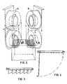
- blower units are autonomous and designed to be exchanged easily. It is easily to diconnect the blower unit from the power card by one plug and mechanicly from the computer housing by loosing one screw.
- Air inlet openings infront of each blower unit are covered with moving multiple flaps. These flaps are designed that they will be closed automatically by the pressure generated by the operating blower unit for preventing an air-short circuit. For that no special control means and mechanics are required.
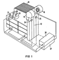
- a computer system has a housing 10 which encloses the internal circuit boards and other computer components and which has an air inlet for receiving air for ventilation and cooling and it has an air outlet for exhausting air from the housing which has been circulated through an air plenum for two blower units with air distribution guides from the air inlet to the air outlet thereby cooling the internal computer components.
- An air plenum 12 is positioned adjacent the housing 10.
- the air plenum 12 has one or more openings which align with the air outlet openings for receiving the air once it has circulated through the housing 10.
- the air plenum has one or more outlets through which the air is passed to another component or unit for cooling in serial the cooling system provides fans 14 and 16 and sensor means 20 ... 25 which monitors the detected failures to the computer system and to switching circuits 26 and 27.
- the cooling system includes the two cooling fans 14 and 16 which may be axial or radial fans as are well known in the art.
- each fan takes in air, accelerates it and exhausts it into the computer housing 10.
- the exhaust air of each fan passes through an exhaust port or opening.
- Each port or opening preferably has a set of flaps which is hingedly connected to the inlet of the plenum which is held open by the pressure of the air flow eminating therefrom.
- the flap falls by the pressure of the operating blower and closes the opening or the flap may be spring assisted to ensure positive closing.
- the sensor means In case of blower unit failure the sensor means, e. g. pressure sensors, detects the fault and activates the control means for switching the operating blower unit to full speed.
- the sensor means are able to monitor the failure to the computer system for announcing this to the system operator. If one fan operates alone, it is operated at 100 % of the rated capacity which provides sufficient air flow to the computer to control the computer temperature within prescribed limits.
- the air flow of the fans is controlled by adjusting the fan rotational speed.
- the switching circuits are used to change the fan speed.
- the switching circuits 26, 27 changes fan speed in response to a signal which is received from the sensor associated with each fan.
- An air flow sensor for example, might consist of a micro-switch or preferable of a pressure sensor which is actuated when the flap closes. Closure of the flap would indicate that there is no air flow to keep it open and will alert the control unit to increase the air output of the other fan.
- fans 14 and 16 operate at a reduced capacity, e. g. 70 %, circulating air through the computer housing 10.
- the air flow forces the flaps open and the micro-switches/pressure sensors inactivate.
- the associated flap will close activating the micro-switch/pressure sensor which alerts the control unit 18 that one of the fans has failed.
- the control unit then increases the output of the remaining operating fan from 70 % of its rated capacity to 100 % of its rated capacity thereby insuring that the minimum air flow required to keep the computer within the prescribed temperature limits is maintained. Since each motor can provide 100 % of the air flow required to keep the computer system within the prescribed temperature limits, the system can run indefinitely on a single fan.
- Routine maintenance can be performed by simply removing a fan which causes the flap by disonnecting the power plug and one screw to close operating the micro-switch/pressure sensor which alerts the control unit that the air flow has ceased whereupon it increases the output of the remaining fan to 100 % of capacity. In this manner, maintenance can be scheduled at convenient times without having to shut the system down.
Landscapes
- Engineering & Computer Science (AREA)
- Microelectronics & Electronic Packaging (AREA)
- Physics & Mathematics (AREA)
- Theoretical Computer Science (AREA)
- Thermal Sciences (AREA)
- Human Computer Interaction (AREA)
- General Engineering & Computer Science (AREA)
- General Physics & Mathematics (AREA)
- Cooling Or The Like Of Electrical Apparatus (AREA)
Applications Claiming Priority (2)
| Application Number | Priority Date | Filing Date | Title |
|---|---|---|---|
| US13311487A | 1987-12-14 | 1987-12-14 | |
| US133114 | 2008-06-04 |
Publications (2)
| Publication Number | Publication Date |
|---|---|
| EP0320720A2 true EP0320720A2 (de) | 1989-06-21 |
| EP0320720A3 EP0320720A3 (de) | 1990-01-10 |
Family
ID=22457084
Family Applications (1)
| Application Number | Title | Priority Date | Filing Date |
|---|---|---|---|
| EP88120178A Withdrawn EP0320720A3 (de) | 1987-12-14 | 1988-12-02 | Ununterbrochenes Kühlungssystem für einen Computer |
Country Status (1)
| Country | Link |
|---|---|
| EP (1) | EP0320720A3 (de) |
Cited By (8)
| Publication number | Priority date | Publication date | Assignee | Title |
|---|---|---|---|---|
| EP0442642A3 (en) * | 1990-02-15 | 1992-04-29 | International Business Machines Corporation | Multi unit electrical apparatus with forced air cooling |
| GB2295669A (en) * | 1994-11-29 | 1996-06-05 | Int Computers Ltd | Forced air cooling arrangement for electronic equipment |
| US5963887A (en) * | 1996-11-12 | 1999-10-05 | The United States Of America As Represented By The Secretary Of The Navy | Apparatus for optimizing the rotational speed of cooling fans |
| GB2354316A (en) * | 1999-09-14 | 2001-03-21 | Lucent Technologies Inc | Cabinet for units which dissipate heat |
| GB2409348A (en) * | 2003-12-12 | 2005-06-22 | Cray Canada Inc | Servicing cooling systems for electronic devices |
| GB2410379A (en) * | 2004-01-23 | 2005-07-27 | Hewlett Packard Development Co | Redundant fan cooling system |
| DE10201445B4 (de) * | 2001-01-17 | 2006-03-09 | Delta Electroncis, Inc. | Wärmeableitsystem |
| US11071235B2 (en) | 2018-12-18 | 2021-07-20 | International Business Machines Corporation | Airflow balancing assembly |
Family Cites Families (3)
| Publication number | Priority date | Publication date | Assignee | Title |
|---|---|---|---|---|
| GB8407992D0 (en) * | 1984-03-28 | 1984-05-10 | Howorth Air Eng Ltd | Air conditioning system |
| JPS61216011A (ja) * | 1985-02-22 | 1986-09-25 | Fujitsu Ltd | 電子装置の冷却系制御装置 |
| US4648007A (en) * | 1985-10-28 | 1987-03-03 | Gte Communications Systems Corporation | Cooling module for electronic equipment |
-
1988
- 1988-12-02 EP EP88120178A patent/EP0320720A3/de not_active Withdrawn
Cited By (14)
| Publication number | Priority date | Publication date | Assignee | Title |
|---|---|---|---|---|
| US5168424A (en) * | 1990-02-15 | 1992-12-01 | International Business Machines Corporation | Multi unit electrical apparatus with dual inlet fan positioned opposite unit bays |
| EP0442642A3 (en) * | 1990-02-15 | 1992-04-29 | International Business Machines Corporation | Multi unit electrical apparatus with forced air cooling |
| GB2295669A (en) * | 1994-11-29 | 1996-06-05 | Int Computers Ltd | Forced air cooling arrangement for electronic equipment |
| US5963887A (en) * | 1996-11-12 | 1999-10-05 | The United States Of America As Represented By The Secretary Of The Navy | Apparatus for optimizing the rotational speed of cooling fans |
| GB2354316A (en) * | 1999-09-14 | 2001-03-21 | Lucent Technologies Inc | Cabinet for units which dissipate heat |
| GB2354316B (en) * | 1999-09-14 | 2001-09-12 | Lucent Technologies Inc | Cabinet for units which dissipate heat |
| DE10201445B4 (de) * | 2001-01-17 | 2006-03-09 | Delta Electroncis, Inc. | Wärmeableitsystem |
| GB2409348A (en) * | 2003-12-12 | 2005-06-22 | Cray Canada Inc | Servicing cooling systems for electronic devices |
| US7017059B2 (en) | 2003-12-12 | 2006-03-21 | Cray Canada Inc. | Methods and apparatus for replacing cooling systems in operating computers |
| US7219247B2 (en) | 2003-12-12 | 2007-05-15 | Cray Canada Inc. | Methods and apparatus for replacing cooling systems in operating computers |
| GB2409348B (en) * | 2003-12-12 | 2007-08-22 | Cray Canada Inc | Methods and apparatus for replacing cooling systems in operating computers |
| GB2410379A (en) * | 2004-01-23 | 2005-07-27 | Hewlett Packard Development Co | Redundant fan cooling system |
| GB2410379B (en) * | 2004-01-23 | 2007-08-08 | Hewlett Packard Development Co | Redundant fan system in a turbo cooler assembly |
| US11071235B2 (en) | 2018-12-18 | 2021-07-20 | International Business Machines Corporation | Airflow balancing assembly |
Also Published As
| Publication number | Publication date |
|---|---|
| EP0320720A3 (de) | 1990-01-10 |
Similar Documents
| Publication | Publication Date | Title |
|---|---|---|
| US20030112600A1 (en) | Chassis with adaptive fan control | |
| US6936767B2 (en) | Apparatus for continuous cooling of electrical powered equipment | |
| US6968709B2 (en) | System and method for cooling multiple logic modules | |
| US9438087B2 (en) | Energy reclamation from air-moving systems | |
| US6597972B2 (en) | Integrated fan assembly utilizing an embedded fan controller | |
| US20040100765A1 (en) | Server blade chassis with airflow bypass damper engaging upon blade removal | |
| CN102439372B (zh) | 空调装置及空调系统 | |
| JPS61216011A (ja) | 電子装置の冷却系制御装置 | |
| US7369406B2 (en) | Disk array apparatus | |
| EP1709855A2 (de) | Selbstkühlungs-gehäuse für elektronische geräte mit ausfalltoerantem kühlsystem und betriebsverfahren | |
| EP0320720A2 (de) | Ununterbrochenes Kühlungssystem für einen Computer | |
| CN100381031C (zh) | 通风装置 | |
| JP2000112574A (ja) | 冷却ファン制御方式 | |
| US6386826B1 (en) | Fan with self closing blades | |
| US20070293137A1 (en) | Acoustic noise reduction using airflow management | |
| US5241253A (en) | Controller for two-speed fans in VAV systems having inlet vanes | |
| JPH03257337A (ja) | 電子装置の温度異常検出回路 | |
| JP2000187975A (ja) | ディスクアレイ装置 | |
| US3885200A (en) | Monitoring arrangement for a blower | |
| US20030209945A1 (en) | Cross ventilation technique for cooling redundant power supplies | |
| EP0421743A2 (de) | Kühlmittelzufuhrvorrichtung für elektronische Einrichtung mit Flüssigkeitskühlung | |
| JPH06272694A (ja) | 電子機器用冷却ファン制御方法および装置 | |
| JPH0735940B2 (ja) | 冷却装置 | |
| EP1825346B1 (de) | Kühlsystem für elektrische schaltschränke | |
| JP2529977B2 (ja) | ファンユニット |
Legal Events
| Date | Code | Title | Description |
|---|---|---|---|
| PUAI | Public reference made under article 153(3) epc to a published international application that has entered the european phase |
Free format text: ORIGINAL CODE: 0009012 |
|
| AK | Designated contracting states |
Kind code of ref document: A2 Designated state(s): CH DE ES FR GB IT LI |
|
| PUAL | Search report despatched |
Free format text: ORIGINAL CODE: 0009013 |
|
| AK | Designated contracting states |
Kind code of ref document: A3 Designated state(s): CH DE ES FR GB IT LI |
|
| STAA | Information on the status of an ep patent application or granted ep patent |
Free format text: STATUS: THE APPLICATION IS DEEMED TO BE WITHDRAWN |
|
| 18D | Application deemed to be withdrawn |
Effective date: 19900711 |