EP0320743A2 - Magnétoscope avec une bande vidéo comprenant une piste de contrôle additionnelle - Google Patents
Magnétoscope avec une bande vidéo comprenant une piste de contrôle additionnelle Download PDFInfo
- Publication number
- EP0320743A2 EP0320743A2 EP88120311A EP88120311A EP0320743A2 EP 0320743 A2 EP0320743 A2 EP 0320743A2 EP 88120311 A EP88120311 A EP 88120311A EP 88120311 A EP88120311 A EP 88120311A EP 0320743 A2 EP0320743 A2 EP 0320743A2
- Authority
- EP
- European Patent Office
- Prior art keywords
- tape
- video
- target
- drive control
- marking
- Prior art date
- Legal status (The legal status is an assumption and is not a legal conclusion. Google has not performed a legal analysis and makes no representation as to the accuracy of the status listed.)
- Granted
Links
- 238000001514 detection method Methods 0.000 claims description 15
- 238000010586 diagram Methods 0.000 description 7
- 230000000712 assembly Effects 0.000 description 1
- 238000000429 assembly Methods 0.000 description 1
- 238000001914 filtration Methods 0.000 description 1
- 239000003550 marker Substances 0.000 description 1
- 230000001360 synchronised effect Effects 0.000 description 1
Images

Classifications
-
- G—PHYSICS
- G11—INFORMATION STORAGE
- G11B—INFORMATION STORAGE BASED ON RELATIVE MOVEMENT BETWEEN RECORD CARRIER AND TRANSDUCER
- G11B27/00—Editing; Indexing; Addressing; Timing or synchronising; Monitoring; Measuring tape travel
- G11B27/10—Indexing; Addressing; Timing or synchronising; Measuring tape travel
- G11B27/19—Indexing; Addressing; Timing or synchronising; Measuring tape travel by using information detectable on the record carrier
- G11B27/28—Indexing; Addressing; Timing or synchronising; Measuring tape travel by using information detectable on the record carrier by using information signals recorded by the same method as the main recording
- G11B27/32—Indexing; Addressing; Timing or synchronising; Measuring tape travel by using information detectable on the record carrier by using information signals recorded by the same method as the main recording on separate auxiliary tracks of the same or an auxiliary record carrier
-
- G—PHYSICS
- G11—INFORMATION STORAGE
- G11B—INFORMATION STORAGE BASED ON RELATIVE MOVEMENT BETWEEN RECORD CARRIER AND TRANSDUCER
- G11B15/00—Driving, starting or stopping record carriers of filamentary or web form; Driving both such record carriers and heads; Guiding such record carriers or containers therefor; Control thereof; Control of operating function
- G11B15/02—Control of operating function, e.g. switching from recording to reproducing
- G11B15/026—Control of operating function, e.g. switching from recording to reproducing by using processor, e.g. microcomputer
-
- G—PHYSICS
- G11—INFORMATION STORAGE
- G11B—INFORMATION STORAGE BASED ON RELATIVE MOVEMENT BETWEEN RECORD CARRIER AND TRANSDUCER
- G11B27/00—Editing; Indexing; Addressing; Timing or synchronising; Monitoring; Measuring tape travel
- G11B27/10—Indexing; Addressing; Timing or synchronising; Measuring tape travel
- G11B27/102—Programmed access in sequence to addressed parts of tracks of operating record carriers
- G11B27/107—Programmed access in sequence to addressed parts of tracks of operating record carriers of operating tapes
Definitions
- the invention relates to a video recorder according to the preamble of claim 1.
- a video recorder is known from DE-OS 34 12 735.
- the known video recorder contains a drive control device, on which not only a fast search of the video tape can be set and in which the video presentation recorded on the video tape is scanned, but also a so-called quick run of the video tape can be set, in which the video tape outside of one Scan setting is rewound.
- a special computing device of the known video recorder ensures that the respective tape position of the video tape with respect to the scanning point is continuously determined even when the video tape is fast-moving. This device is intended, inter alia, to make a video presentation recorded on the video tape, the beginning of which was noted as the tape position, relatively quickly to find.
- the determination of the tape position during the fast running of the video tape is not so precise that the tape position displayed on the video recorder is actually the tape position of the beginning of the video presentation sought. Rather, the user of the known video recorder has to switch on the fast search after stopping the fast run in order to find the desired video presentation with a more or less great expenditure of time in a forward run or a reverse run of the video tape.
- a device is known with which a time code is additionally recorded on the so-called control track for synchronization of the video images recorded on the video tape of a video presentation.
- the image reproduction from the video tape is synchronized by means of the leading edge of the control pulses contained on the control track.
- the position of the trailing edges of these pulses is used for the time code.
- the time code continuously represents the previously elapsed running time of the video tape.
- a time specification extends over at least 50 control pulses, so that there is a newspaper inaccuracy of a few seconds.
- the device for recording this time code and a device for scanning and evaluating this time code require a relatively large outlay, which is not suitable for using such devices on a larger scale in video devices of consumer electronics.
- this time code is of little use if the user of the video recorder was wrong by a few minutes in noting the tape position for the beginning of a video performance recorded on the video tape.
- the object of the invention is to enable the beginning of a desired video presentation recorded on a video tape to be found with pinpoint accuracy in a video recorder mentioned at the outset without disturbing the image reproduction. This object is achieved according to the invention by the measures specified in the characterizing part of claim 1 or claim 2.
- the measures according to the invention a very fast finding of the beginning of a desired video presentation recorded on a video tape is made possible, since the majority of the target run of the video tape is carried out in a quick run to the entered target position, in which the tape very quickly immediately in the Video cassette is rewound. Only at the entered target position is the tape pulled out of the video cassette and guided past a scanning head which scans the control track of the video tape. As a result, the video tape is only exposed to negligible tape wear on the scanning heads. In addition, the target run and the type of start marker in no way affect the playback of video performances recorded on the video tape.
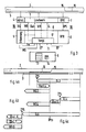
- the drive 1 shows a block diagram for drive control of a video recorder, in the drive 1 of which a video tape 2 is inserted.
- the video tape 2 contains a control signal track 3 with control signals which are scanned by a scanning device 4 of the drive 1 and are fed as control signals StS to a detection circuit 5 of a drive control device 6 of the video recorder for synchronizing the reproduction of the video performances recorded on the video tape 2.
- the drive 1 also contains a tape position signal transmitter 7, which forwards tape position signals BPS to a tape position computer 8 of the drive control device 6.
- the drive control device is used to set the various operating states of the drive 1 of the VCRs.
- the drive 1 is set by a signal combination WG in the operating state of the scanning and playback of a video presentation recorded on the video tape 2 or by a signal combination SL of the drive control device 6 in a fast run SL in which the video tape 2 is not closer to it shown video cassette is rewound from the video cassette without unthreading the video tape, or set by a signal combination SSuL in a fast search SSuL, in which the video tape 2 threaded into the drive 1 is scanned at a running speed that is significantly higher than the playback speed.
- a forward / backward signal V / R of the drive control device 6 determines the running direction of the fast run SL and the fast search run SSuL.
- the operating states of the drive control device 6 or of the video recorder can be selected by the user on an operating device 9.
- the control signal track 3 contains, in addition to the control signals, a target marking 10 which, for example, marks the beginning of a video presentation recorded on the video tape 2 in a picture-precise manner.
- the video recorder according to FIG. 1 is set up to find this target marking 10 on the video tape 2 and to reproduce the video presentation marked with it from the video tape.
- the drive control device 6 contains a comparator circuit 11 or a comparator program and a position distance calculator 12 or a position distance calculation program.
- the target position ZP namely the tape position at which the target mark 10 for the beginning of the sought-for video presentation recorded on the video tape is to be located Entered via an input arrangement 13 of the operating device and identified by operating an operating element 14, which triggers the target run ZL to find the entered target position ZP, and fed to the position path computer 12.
- the position path computer 12 forms a specific position path PStr around the target position ZP.
- the extent of the position distance around the target position ZP is dimensioned such that it is greater than the accuracy range for setting the target position ZP to the actual tape position BP of the target marking 10 on the video tape 2.
- the comparator circuit 11 provides a comparison with the entered target position ZP the tape position BP output by the tape position computer 8 determines in which direction the drive control device 6 must set the fast run SL for the finish run to the entered target position.
- This fast run is indicated in the flowchart of FIG. 2a for the functional or program sequence of the drive control device 6 shown in FIG. 1 by an arrow SL1. If the tape position BP output by the tape position computer 8 becomes the position value ZPA1 calculated by the position link computer 12 for the start of the position link PStr1, the comparator circuit 11 switches the drive 1 via the drive control device 6 from the fast run SL to the fast search run SSul with the same running direction as that Fast forward to what is shown in FIG.
- the recognition circuit 5 recognizes this target position ZP1 within the position path PStr1 of the target position entered on the input device 13 and outputs a target mark signal ZM
- the fast search SSuL1 stopped and the drive control device 6 set by the target signal ZM in the playback mode, which also sets the drive 1 in the playback mode WG1, which is shown schematically by the arrow WG1.
- the fast search run SSuL2 which is switched on after the fast run SL2 at the start ZPA2 of the position path PStr2 runs through the entire position path and is switched in the opposite direction at the end ZPE2 of this position path, which is shown in FIG. 2b by the arrow SSuL3.
- the fast search in the opposite direction is stopped and, in the exemplary embodiment shown in FIG.
- the drive control device 6 is switched to the playback operating state, which is indicated in the flowchart in FIG. 2b the arrow WG2 is shown schematically. In this way, if no target marking 10 is recognized, the input target position ZP2 is evaluated as the beginning of the selected video presentation.
- the video recorder differs from the video recorder shown in FIG. 1 essentially in that the data recorded on the control signal track 3 of the video tape 2 in addition to the control signals Target markings is the beginning 15 of a marking section 16 occupied by a marking signal.
- Corresponding assemblies and devices are designated by the same reference numerals in FIGS. 1 and 3. Accordingly, the comparator circuit 17 of the drive control device 6 of the video recorder shown in FIG. 3 differs from the comparator circuit 11 of the drive control device 6 of the video recorder shown in FIG. 1.
- the comparator circuit 17 sets the drive 1 in a fast run SL in the direction of the entered target position ZP3, ZP4 or ZP5 until the device 18 formed from the tape position transmitter 7 and the tape position computer 8 outputs a tape position BP for determining and outputting the tape position, which is equal to the entered target position. With this coincidence, drive 1 is switched from fast run SL3, SL4 or SL5 to fast search run SSuL4, SSuL5 or SSuL6.
- the direction of the fast search run depends on whether or not the detection device 19 formed from the scanning device 4 and the detection circuit 5 detects marking signals of a marking path 16. If the device detects 19 marking signals, it outputs a corresponding marking signal ZM for the duration of the detection, which signals the opposite direction of the fast search SSuL4 specifies, as shown in the flow chart of Fig. 4a.
- the comparator circuit 17 switches the drive control device 6 into the playback state, so that the drive 1 is also set to the playback state WG3 (arrow WG3 in FIG. 4a).
- the reproduction of a video presentation recorded on the video tape 2 thus begins at the beginning 15 of the marking route belonging to this recording.
- the length of the marking section 16 is dimensioned so long that it is greater than the expected accuracy of finding the tape position BPm of the beginning 15 of the marking section 16 recorded on the control signal track for the beginning of the associated video presentation on the video tape 2.
- the detection device 19 does not generate a marking signal ZM within a predetermined running distance of the fast search run SSuL6, which is greater than the accuracy range for finding a tape position, which is equal to the entered target position, which is schematically represented by the arrow SSuL6 in the flowchart in FIG. 4c , the comparator circuit switches the fast search in the opposite direction (arrow SSuL7) until the tape position BP output by the tape position computer 8 is equal to the entered target position ZP5.
- the comparator circuit 17 switches the drive control device 6 into the playback state, by means of which the drive 1 is also set into the playback state (arrow WG5 in the flowchart in FIG. 4c). This ensures that if no target mark 16 is recognized in the fast search (SSuL6) after a predetermined tape path, the entered target position ZP5 is evaluated as the beginning of the video presentation to be reproduced.
- a video tape 2 is used, on the control signal track 3 of which, in addition to the control signals and the target marking 16, one Marking identifier is recorded.
- This marking identifier is only recorded continuously on the control signal track 3 of the video tape if the control signal track 3 contains at least one target marking 16 at the same time.
- the detection circuit 5 of the detection device 19 of the The video recorder is set up in such a way that it recognizes the marking identifier and outputs a marking signal MS when scanning and recognizing such a marking identifier.
Landscapes
- Engineering & Computer Science (AREA)
- Computer Hardware Design (AREA)
- Indexing, Searching, Synchronizing, And The Amount Of Synchronization Travel Of Record Carriers (AREA)
- Management Or Editing Of Information On Record Carriers (AREA)
- Radar Systems Or Details Thereof (AREA)
- Signal Processing Not Specific To The Method Of Recording And Reproducing (AREA)
Priority Applications (1)
| Application Number | Priority Date | Filing Date | Title |
|---|---|---|---|
| AT88120311T ATE96571T1 (de) | 1987-12-15 | 1988-12-06 | Videorecorder mit einem eine zusaetzliche steuersignalspur enthaltenden videoband. |
Applications Claiming Priority (2)
| Application Number | Priority Date | Filing Date | Title |
|---|---|---|---|
| DE3742471 | 1987-12-15 | ||
| DE3742471A DE3742471C1 (de) | 1987-12-15 | 1987-12-15 | Videorecorder mit einem eine zusaetzliche Steuersignalspur enthaltenden Videoband |
Publications (3)
| Publication Number | Publication Date |
|---|---|
| EP0320743A2 true EP0320743A2 (fr) | 1989-06-21 |
| EP0320743A3 EP0320743A3 (fr) | 1991-01-30 |
| EP0320743B1 EP0320743B1 (fr) | 1993-10-27 |
Family
ID=6342650
Family Applications (1)
| Application Number | Title | Priority Date | Filing Date |
|---|---|---|---|
| EP88120311A Expired - Lifetime EP0320743B1 (fr) | 1987-12-15 | 1988-12-06 | Magnétoscope avec une bande vidéo comprenant une piste de contrôle additionnelle |
Country Status (5)
| Country | Link |
|---|---|
| EP (1) | EP0320743B1 (fr) |
| JP (1) | JP2701898B2 (fr) |
| AT (1) | ATE96571T1 (fr) |
| DE (2) | DE3742471C1 (fr) |
| ES (1) | ES2049240T3 (fr) |
Families Citing this family (2)
| Publication number | Priority date | Publication date | Assignee | Title |
|---|---|---|---|---|
| EP0448011B1 (fr) * | 1990-03-19 | 1997-11-12 | Canon Kabushiki Kaisha | Appareil de reproduction d'images fixes |
| DE10051557A1 (de) * | 2000-10-18 | 2002-04-25 | Thomson Brandt Gmbh | Spurmarkierung für einen D-VHS Recorder |
Family Cites Families (12)
| Publication number | Priority date | Publication date | Assignee | Title |
|---|---|---|---|---|
| US3851116A (en) * | 1969-12-24 | 1974-11-26 | Ibm | Automatic magnetic tape information retrieval system with speed and position tape drive control |
| GB2131996A (en) * | 1982-11-30 | 1984-06-27 | George Saint | Data storage devices |
| JPS59104738A (ja) * | 1982-12-02 | 1984-06-16 | Victor Co Of Japan Ltd | 頭出し信号記録装置 |
| DE3325810C2 (de) * | 1983-02-04 | 1985-10-17 | Berchtold, Rainer, 8044 Unterschleißheim | Video-Einrichtung |
| JPS60182583A (ja) * | 1984-02-29 | 1985-09-18 | Nippon Telegr & Teleph Corp <Ntt> | カセツトテ−プレコ−ダの頭出し方法 |
| DE3412735A1 (de) * | 1984-04-05 | 1985-10-17 | Standard Elektrik Lorenz Ag, 7000 Stuttgart | Aufnahme- oder wiedergabegeraet der unterhaltungselektronik mit einer anzeigevorrichtung zur anzeige der bandposition |
| US4689699A (en) * | 1984-04-27 | 1987-08-25 | Canon Kabushiki Kaisha | Information signal recording and/or reproducing apparatus |
| ATA399884A (de) * | 1984-12-17 | 1985-11-15 | Alfred Ing Benesch | Zusatzeinrichtung fuer videorekorder zur ermoeglichung einer nahezu sekundengenauen band-ziel-positionierung zur auswahl bestimmter ron-bildaufzeichnungen |
| JPH0795390B2 (ja) * | 1985-08-07 | 1995-10-11 | 株式会社日立製作所 | 磁気記録再生装置の制御信号記録装置 |
| JPH0664898B2 (ja) * | 1985-11-20 | 1994-08-22 | 松下電器産業株式会社 | 磁気記録再生装置 |
| DE3543686A1 (de) * | 1985-12-11 | 1987-06-19 | Thomson Brandt Gmbh | Verfahren zum abspeichern von daten auf einem aufzeichnungstraeger |
| US4811127A (en) * | 1986-10-22 | 1989-03-07 | Victor Company Of Japan, Ltd. | Magnetic recording and reproducing apparatus |
-
1987
- 1987-12-15 DE DE3742471A patent/DE3742471C1/de not_active Expired
-
1988
- 1988-12-06 ES ES88120311T patent/ES2049240T3/es not_active Expired - Lifetime
- 1988-12-06 EP EP88120311A patent/EP0320743B1/fr not_active Expired - Lifetime
- 1988-12-06 DE DE88120311T patent/DE3885250D1/de not_active Expired - Lifetime
- 1988-12-06 AT AT88120311T patent/ATE96571T1/de not_active IP Right Cessation
- 1988-12-15 JP JP63317552A patent/JP2701898B2/ja not_active Expired - Lifetime
Also Published As
| Publication number | Publication date |
|---|---|
| JP2701898B2 (ja) | 1998-01-21 |
| EP0320743B1 (fr) | 1993-10-27 |
| DE3885250D1 (de) | 1993-12-02 |
| ES2049240T3 (es) | 1994-04-16 |
| EP0320743A3 (fr) | 1991-01-30 |
| JPH01311493A (ja) | 1989-12-15 |
| DE3742471C1 (de) | 1989-05-24 |
| ATE96571T1 (de) | 1993-11-15 |
Similar Documents
| Publication | Publication Date | Title |
|---|---|---|
| DE2702780C2 (de) | Bandschnittsteuereinrichtung mit zwei Videomagnetbandgeräten | |
| DE19818501C2 (de) | Verfahren zur Feinaufzeichnung von Videorahmen | |
| DE2645747C2 (de) | Verfahren zur Wiedergabe von einzelnen Bildern von auf bandförmigen Trägern aufgezeichneten Fernsehsignalen | |
| DE3621263A1 (de) | Aufzeichnungs- und wiedergabegeraet mit einem aufzeichnungstraeger | |
| EP0424653A1 (fr) | Magnétoscope avec un dispositif pour enregistrer la table de matières d'un magasin de cassettes pour plusieurs cassettes à bandes magnétiques | |
| DE3904344A1 (de) | Verfahren zum lesen von navigationsdaten einer compact-disc | |
| EP0029946A1 (fr) | Dispositions pour enregistrer et retrouver des positions sur des supports d'enregistrements en forme de bande dans un appareil d'enregistrement et/ou de reproduction | |
| DE3785309T2 (de) | Verfahren und geraet zur bestimmung der kante eines magnetbandes. | |
| DE69616064T2 (de) | Automatisierung der wiedergabe einer videoaufnahme | |
| DE3726367A1 (de) | Markierungssignale und markierungsdatenbloecke fuer den einsatz mit aufgenommenen mitteilungen | |
| DE3016059C2 (de) | Bandstellensucheinrichtung für ein magnetisches Aufnahme- und Wiedergabegerät | |
| EP0248945A2 (fr) | Procédé pour transmettre un code d'information sur la piste de synchronisation d'une bande vidéo, dispositif pour mettre en oeuvre le procédé de même que la bande vidéo fabriquée selon le procédé | |
| DE1096404B (de) | Verfahren und Einrichtung zur regiemaessigen Bearbeitung von Fernsehaufzeichnungen | |
| EP0320743B1 (fr) | Magnétoscope avec une bande vidéo comprenant une piste de contrôle additionnelle | |
| DE3742469C1 (de) | Videorecorder mit einer Einrichtung zur Aufzeichnung einer zusaetzlichen Steuersignalspur auf ein Videoband | |
| DE2829476A1 (de) | Verfahren und vorrichtung zur audiovisuellen wiedergabe von informationen | |
| DE3309029C2 (de) | Verfahren zum Bestimmen der momentanen Bandlänge eines Videomagnetbandes und nach diesem Verfahren bespielte Videomagnetbänder | |
| DE3028691C2 (de) | Magnetbandgerät | |
| AT393569B (de) | System zum aufzeichnen und auswerten von markiersignalen | |
| DE3542307A1 (de) | Tonfrequenzsignal-aufzeichnungsgeraet | |
| DE3347231C2 (fr) | ||
| DE69522312T2 (de) | Verfahren und vorrichtung zur aufzeichnungsmedienwiedergabe und/oder -aufnahme | |
| DE2939499C2 (de) | Steuereinrichtung für den Antrieb eines Wiedergabegerätes | |
| DE2755243A1 (de) | Tonfilmprojektor | |
| EP0583638B1 (fr) | Lecteur de CD |
Legal Events
| Date | Code | Title | Description |
|---|---|---|---|
| PUAI | Public reference made under article 153(3) epc to a published international application that has entered the european phase |
Free format text: ORIGINAL CODE: 0009012 |
|
| AK | Designated contracting states |
Kind code of ref document: A2 Designated state(s): AT BE DE ES FR GB IT NL |
|
| RAP1 | Party data changed (applicant data changed or rights of an application transferred) |
Owner name: NOKIA UNTERHALTUNGSELEKTRONIK (DEUTSCHLAND) GMBH |
|
| PUAL | Search report despatched |
Free format text: ORIGINAL CODE: 0009013 |
|
| AK | Designated contracting states |
Kind code of ref document: A3 Designated state(s): AT BE DE ES FR GB IT NL |
|
| 17P | Request for examination filed |
Effective date: 19910722 |
|
| RAP1 | Party data changed (applicant data changed or rights of an application transferred) |
Owner name: NOKIA (DEUTSCHLAND) GMBH |
|
| 17Q | First examination report despatched |
Effective date: 19920910 |
|
| GRAA | (expected) grant |
Free format text: ORIGINAL CODE: 0009210 |
|
| AK | Designated contracting states |
Kind code of ref document: B1 Designated state(s): AT BE DE ES FR GB IT NL |
|
| REF | Corresponds to: |
Ref document number: 96571 Country of ref document: AT Date of ref document: 19931115 Kind code of ref document: T |
|
| ITF | It: translation for a ep patent filed | ||
| REF | Corresponds to: |
Ref document number: 3885250 Country of ref document: DE Date of ref document: 19931202 |
|
| GBT | Gb: translation of ep patent filed (gb section 77(6)(a)/1977) |
Effective date: 19931109 |
|
| ET | Fr: translation filed | ||
| REG | Reference to a national code |
Ref country code: ES Ref legal event code: FG2A Ref document number: 2049240 Country of ref document: ES Kind code of ref document: T3 |
|
| PLBE | No opposition filed within time limit |
Free format text: ORIGINAL CODE: 0009261 |
|
| STAA | Information on the status of an ep patent application or granted ep patent |
Free format text: STATUS: NO OPPOSITION FILED WITHIN TIME LIMIT |
|
| 26N | No opposition filed | ||
| REG | Reference to a national code |
Ref country code: GB Ref legal event code: IF02 |
|
| REG | Reference to a national code |
Ref country code: GB Ref legal event code: 732E |
|
| NLS | Nl: assignments of ep-patents |
Owner name: SOCIETA ITALIANA PER LO SVILUPPO DELL'ELETTRONICA |
|
| REG | Reference to a national code |
Ref country code: FR Ref legal event code: TP |
|
| REG | Reference to a national code |
Ref country code: ES Ref legal event code: PC2A |
|
| PGFP | Annual fee paid to national office [announced via postgrant information from national office to epo] |
Ref country code: ES Payment date: 20071210 Year of fee payment: 20 Ref country code: NL Payment date: 20071211 Year of fee payment: 20 |
|
| PGFP | Annual fee paid to national office [announced via postgrant information from national office to epo] |
Ref country code: IT Payment date: 20071220 Year of fee payment: 20 Ref country code: AT Payment date: 20071210 Year of fee payment: 20 |
|
| PGFP | Annual fee paid to national office [announced via postgrant information from national office to epo] |
Ref country code: BE Payment date: 20071211 Year of fee payment: 20 |
|
| PGFP | Annual fee paid to national office [announced via postgrant information from national office to epo] |
Ref country code: GB Payment date: 20071121 Year of fee payment: 20 |
|
| PGFP | Annual fee paid to national office [announced via postgrant information from national office to epo] |
Ref country code: DE Payment date: 20071210 Year of fee payment: 20 |
|
| PGFP | Annual fee paid to national office [announced via postgrant information from national office to epo] |
Ref country code: FR Payment date: 20071221 Year of fee payment: 20 |
|
| BE20 | Be: patent expired |
Owner name: *SOCIETA ITALIANA PER LO SVILUPPO DELL'ELETTRONICA Effective date: 20081206 |
|
| REG | Reference to a national code |
Ref country code: GB Ref legal event code: PE20 Expiry date: 20081205 |
|
| PG25 | Lapsed in a contracting state [announced via postgrant information from national office to epo] |
Ref country code: NL Free format text: LAPSE BECAUSE OF EXPIRATION OF PROTECTION Effective date: 20081206 |
|
| REG | Reference to a national code |
Ref country code: ES Ref legal event code: FD2A Effective date: 20081209 |
|
| PG25 | Lapsed in a contracting state [announced via postgrant information from national office to epo] |
Ref country code: ES Free format text: LAPSE BECAUSE OF EXPIRATION OF PROTECTION Effective date: 20081209 |
|
| PG25 | Lapsed in a contracting state [announced via postgrant information from national office to epo] |
Ref country code: GB Free format text: LAPSE BECAUSE OF EXPIRATION OF PROTECTION Effective date: 20081205 |