EP0320797A1 - Dispositif pour emballer des produits d'imprimerie - Google Patents
Dispositif pour emballer des produits d'imprimerie Download PDFInfo
- Publication number
- EP0320797A1 EP0320797A1 EP88120520A EP88120520A EP0320797A1 EP 0320797 A1 EP0320797 A1 EP 0320797A1 EP 88120520 A EP88120520 A EP 88120520A EP 88120520 A EP88120520 A EP 88120520A EP 0320797 A1 EP0320797 A1 EP 0320797A1
- Authority
- EP
- European Patent Office
- Prior art keywords
- stack
- banding
- stacking
- stacking device
- copies
- Prior art date
- Legal status (The legal status is an assumption and is not a legal conclusion. Google has not performed a legal analysis and makes no representation as to the accuracy of the status listed.)
- Granted
Links
- 238000004806 packaging method and process Methods 0.000 title claims description 19
- 238000000034 method Methods 0.000 claims description 20
- 238000003825 pressing Methods 0.000 claims description 19
- 238000007789 sealing Methods 0.000 claims 1
- 238000003466 welding Methods 0.000 abstract description 9
- 238000011144 upstream manufacturing Methods 0.000 abstract description 2
- 239000011888 foil Substances 0.000 description 4
- 230000001681 protective effect Effects 0.000 description 4
- 230000000284 resting effect Effects 0.000 description 3
- 238000006073 displacement reaction Methods 0.000 description 2
- 238000000926 separation method Methods 0.000 description 2
- 235000015076 Shorea robusta Nutrition 0.000 description 1
- 244000166071 Shorea robusta Species 0.000 description 1
- 230000015572 biosynthetic process Effects 0.000 description 1
- 238000010276 construction Methods 0.000 description 1
- 230000005484 gravity Effects 0.000 description 1
- 210000000056 organ Anatomy 0.000 description 1
- 238000012858 packaging process Methods 0.000 description 1
- 230000001360 synchronised effect Effects 0.000 description 1
Images



Classifications
-
- B—PERFORMING OPERATIONS; TRANSPORTING
- B65—CONVEYING; PACKING; STORING; HANDLING THIN OR FILAMENTARY MATERIAL
- B65B—MACHINES, APPARATUS OR DEVICES FOR, OR METHODS OF, PACKAGING ARTICLES OR MATERIALS; UNPACKING
- B65B27/00—Bundling particular articles presenting special problems using string, wire, or narrow tape or band; Baling fibrous material, e.g. peat, not otherwise provided for
- B65B27/08—Bundling paper sheets, envelopes, bags, newspapers, or other thin flat articles
-
- B—PERFORMING OPERATIONS; TRANSPORTING
- B65—CONVEYING; PACKING; STORING; HANDLING THIN OR FILAMENTARY MATERIAL
- B65H—HANDLING THIN OR FILAMENTARY MATERIAL, e.g. SHEETS, WEBS, CABLES
- B65H2301/00—Handling processes for sheets or webs
- B65H2301/40—Type of handling process
- B65H2301/42—Piling, depiling, handling piles
- B65H2301/422—Handling piles, sets or stacks of articles
- B65H2301/4223—Pressing piles
Definitions
- the invention is based on a method for packaging printed products, in which copies of the preferably folded, glued or stapled products are taken from a preceding station by means of a loading device and fed to a stacking device in which individual specimens are aligned and counted, the specimens being scaled up in the loading device, and the specimens stacked horizontally immovably in the stacking device being transferred to a banding device and enclosed there in a compressed state with a banding agent.
- the invention is also based on a device for packaging preferably folded, glued or stapled copies of printed products, with a loading device for taking over the copies from a preceding station, with a stacking device downstream of the loading device, in which the stack of copies is horizontally immovable via side guides are held, and with a banding device.
- the known packaging device is used to align, scale, stack and package printed products after they have passed through stapling or folding machines.
- the packaging device consists of several individual devices.
- the loose specimens are transported as a shingled stream on a conveyor belt of the loading device and fed to the stacking device.
- the specimens are individually withdrawn from the stream of streams, aligned and counted and stacked in a stacking device.
- the specimens withdrawn from the stream of shales fall into the stack due to gravity device and are held there horizontally immovable by side guides.
- On the bottom of the stacking device there is a protective plate on which the first copy is placed. Depending on the height of the stack to be formed, a protective plate is inserted again after a certain number of copies have been stacked, onto which further copies may then be stacked. Another protective plate is then placed on the top copy of the stack.
- the stacking device itself is arranged on a rotary table which, after completion of the stack in the stacking device, ie after placing the uppermost protective plate, is pivoted by a certain angle until the stacking device comes to rest on a banding device arranged on the circumference of the round table.
- the stack is first pressed in the vertical direction and strapped with the banding agent. After banding, the completely closed stack remains in the stacking device.
- the turntable is pivoted again by an angle in the same direction as before, after which the stacking device is brought into a removal position in which the packaged stacks are removed from the stacking device. Another pivoting movement of the turntable in the same direction brings the empty stacking device into alignment with the loading device again and is ready to pick up specimens from the stream of shed.
- a disadvantage of such a device and the packaging process carried out is that the spatial separation of the three sub-devices or the sub-process steps carried out with them, namely stacking and subsequent transfer to the banding device, pressing, banding and subsequent transfer to the removal station, removal and subsequent transfer back to the stacking device, the entire device is very bulky and the process is cumbersome.
- the object of the present invention is therefore to improve a device or a method for packaging printed products of the type mentioned at the outset in such a way that stacking and banding can be carried out in a simple and space-saving manner.
- the object is achieved according to the method mentioned at the outset in that the stacks formed in the stacking device are transferred directly from the stacking device into the banding device by vertical lowering and at the same time are sunk into the banding means in such a way that the stack comprises the banding means on the bottom and sides and that the banding agent is then placed on the lid side of the stack and sealed.
- the object is achieved with the device mentioned at the outset in that the stacking device has a floor which can be vertically lowered or raised, on which the specimens can be stacked, and in that the floor has an opening which releases at least that floor area of the bottom copy of the stack, to which the banding agent is to be applied and that the banding agent is arranged directly below the stacking device.
- the stack to be packaged only has to be lowered to such an extent that the banding agent can be closed on the top of the top copy of the stack, the loop of the banding agent surrounding the stack being separated from the remaining banding agent, which can then return to its original position.
- the stack provided with the banderole is then removed or pushed off without having to move or pivot the bottom of the stacking device again, after which it is raised again and is ready to receive new copies.
- the sub-process sections take place in sections arranged vertically one below the other, which are lined up and flow into one another, thus being simple and easy to understand.
- the lowerable bottom of the stacking device also immediately forms a working part of the banding device, because its lowering movement with the specimens lying thereon creates the banding means on the bottom and the two side walls of the partial stack, so that circumferential elements for applying the banding agent are eliminated.
- the stacking device has a base plate which can be swiveled horizontally by 180 ° and in which the floor is received, with which it can be swiveled.
- the stacking device can work as a so-called stacker, ie the specimens can be stacked individually or as a partial stack, each offset by 180 °. In the case of folded sheets which tend to cause uneven stack heights in the area of the fold, this then leads to a flat stack formation.
- the lowerable floor as part of the base plate of the stacker can be swiveled with and lowered after placing the sufficient number of copies to the banding device.
- the floor has two floor parts of the same level, which are held by means of supports which are mounted so as to be vertically displaceable in the base plate.
- the bottom can be lowered by means of a pressing device which can be placed on the uppermost copy of the stack.
- a device which is provided for lowering the bottom, at the same time presses the stack lying on the bottom, thus bringing it into the pressed state desired for banding.
- a device carries out two method steps or sub-processes, namely transferring or lowering and pressing, which creates a particularly simple device or a simple method within the scope of the task.
- the banding means is tightened by means of two closing punches arranged on the side of the stack and movable over the top of the stack sealed around the stack.
- displaceable angle rails are attached to the floor, which form corners of the stacking cuboid.
- the specimens stacked on the floor are kept immovable in the horizontal direction. Due to the displacement options, the angle rails can be adapted to different specimen sizes.
- the bottom can be lowered to such an extent that a laterally arranged pressing device can be moved at a distance above the top surface of the top copy of the stack, and the bottom can then be raised to such an extent that the respective stack between the retracted pressing device and the floor has a predetermined value Press pressure is maintained, and that the banding agent is closed in this pressed state.
- This lateral arrangement of the pressing device has the advantage that the vertical space above the bottom of the stacking device is free from the pressing device during stacking and lowering, and that the pressing device is only retracted after the bottom has been lowered with the stack placed thereon. By lifting the floor, the stack is then pressed against the stationary pressing device.
- the floor takes on an additional function as an organ of the pressing device, creating a particularly simple device.
- the floor is connected via four vertical rods provided with a drive, which form the corner points of a quadrilateral, the loading device ending at a square edge and the specimens from the loading device into one, with this approximately level and above the Stacking device arranged, partial stacking device are transferred, which then deposits the partial stack on the bottom of the base plate of a cross-layer pivotable by 180 °.
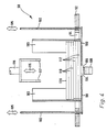
- FIG. 1 shows a highly schematized packaging device 10 according to the invention, which is composed in one structural unit from a loading device 20, a stacking device 30, and a banding device 60.
- the loading device 20 comprises a first and a second conveyor belt 14, 19, between which a press formed by two rollers 15, 16 is arranged.
- the lower roller 16 of the roller pair 15, 16 of the press is connected via a belt 17 to a deflection roller 18 of the conveyor belt 14, which serves as a drive for a synchronous movement of the rollers 14, 15 and 18, and the conveyor belt 14.
- specimens 12 On the conveyor belt 14 are specimens 12 which come from an upstream station in the direction of the arrow 13 to be transported.
- the copies 12 are brought from the conveyor belt 14 between the pair of rollers 15, 16, pressed there and left the pair of rollers 14, 15, lying on the conveyor belt 19, as pressed specimens 22.
- This pressing is carried out in particular in the case of folded specimens, since these tend to partially unfold again after being folded from a one-piece sheet. If such opening folding sheets were later stacked or scaled up, this would result in a very high, uneven stack being formed.
- a ram 24 is arranged, which in the position shown in Fig. 1 is lowered approximately to the surface of the conveyor belt 19, so that the lying on the conveyor belt 19 pressed Specimens 22 are scaled up to a stream of shingles.
- a partial stacking device 31 of the stacking device 30 is arranged, onto which the scaled-up, pressed specimens 22 are conveyed if the ram 24 is raised.
- the partial stacking device 31 is provided with a stop 37 against which the specimens 22 coming from the conveyor belt 19 abut, whereby a partial stack 38 is formed.
- a desired number of copies 22 each reach the partial stacking device 31 by suitably long lifting of the ram 24.
- the partial stacking device 31 is, as indicated by an arrow 36, vertically displaceable and has a bottom which consists of two parts 32 and 33, respectively.
- the parts 32, 33 can be raised or lowered along the arrow 36 by means of piston-cylinder units (not shown here), and can also be moved away from one another, as indicated by the arrows 34 and 35, respectively.
- the bottom parts 32, 33 of the bottom of the partial stacking device 31 lie approximately flush above a bottom 96 of a rotating basket 90 of the stacking device 30, so that if the parts 32, 33 are pulled apart along the arrows 34, 35, a partial stack 38 resting on them is placed on the Bottom 96 of the rotating basket 90 falls.
- the rotating basket 90 can, as indicated by an arrow 91, be pivoted through 180 °, so that it can accommodate the partial stacks 38 coming from the partial stacking device 31, offset by 180 °.
- the rotating basket 90 which is shown enlarged in FIG. 2, has a base plate 92 which is provided with a rectangular central opening 94.
- the bottom 96 which has a first bottom part 98 and a second bottom part 100, is arranged below the base plate 92.
- Each base part 98, 100 is connected to two rods 102, which extend through the base plate 92 and are mounted in a vertically displaceable manner therein.
- the two base parts 98, 100 are rectangular and have a length which is slightly greater than that of the rectangular opening 94. They are spaced apart from one another in the central region of the rectangular opening 94, so that a free space 104 is created.
- the distance between the two mutually facing end faces of the base parts 98, 100, which delimit the space 104, corresponds at least to the width of a film strip 106 which is to be placed around the stack 120 to be packed.
- angle rails 103 Arranged on the bottom side of the bottom parts 98, 100 are two angle rails 103 (see also FIG. 1) which are oriented in such a way that they delimit the four corner edges of the specimens to be packed, i.e. that they occupy corner edges of a cuboid body.
- the angle rails 103 are arranged such that they accommodate the partial stacks 38 falling from the partial stacking device 31 (see FIG. 1).
- the angle rails 103 are adjustable or displaceable so that they can be adapted to different specimen sizes.
- a banding means 106 in the form of a film band of the banding device 60 is arranged, which protrudes on both sides of the base plate 92 and is wound on opposing rollers 108.
- rollers 108 are provided with tensioning devices, not shown here, which tend to hold the belt in the tight orientation shown in FIG. 2.
- the bottom 96 In the position shown in FIGS. 1 and 2, the bottom 96 is in its uppermost position, in which it comes to rest just below the base plate 92 of the rotating basket 90.
- the bottom 96 of the rotating basket 90 is designed to be lowerable.
- 3a to 3f schematically show a partial view of the packaging device 10 shown in FIG. 1 in the area of the rotating basket in the direction of an arrow 72.
- FIG. 3a corresponds to the uppermost position of the bottom 96 shown in solid lines in FIG. 1.
- the angle rails 103 are omitted in the schematic illustration of FIGS. 3a to 3f. 3a to 3f, the bottom part 100 can be seen from the bottom 96.
- the specimens lying on the floor 96 lie on both floor parts 98 and 100 and partially cover the gap-like space 104 (see FIG. 2) between the two floor parts 98 and 100.
- the film strip 106 runs over two level support rollers 114 (see FIGS. 3a to 3f), which are arranged so that the Foil tape 106 runs horizontally in the uppermost position of the lowerable bottom 96.
- the support rollers 114 are horizontally displaceable and are each positioned in such a way that imaginary extension lines of the sides of the stack 120 lying on the floor run approximately tangentially at the two, opposite and facing inner circumferential points of the support rollers 114.
- two bars 64, 66 of a pressing device 62 are arranged which, as indicated by the arrows 68 in FIG. 1 and FIG. 3b, can be displaced horizontally.
- the bars 64, 66 are guided over plain bearings, not shown here, and connected at their end facing away from the rotating basket 90 to a piston-cylinder unit.
- the floor (in each case part 100 can be seen in FIGS. 3a to 3f) is lowered so far that the uppermost copy of the stack 120 comes to rest at a distance below the two level beams 64, 66 (see FIG. 3b).
- the lowering movement is stopped and the beams 64, 66 move over the stack 120.
- the bars 64, 66 are arranged in such a way that the bar 66, as seen in the direction of the arrows 68, moves to the left of the film strip 106 and the beam 64 to the right of the film strip 106 lies above the stack 120 (see FIG. 3c or Fig. 1).
- the floor 96 is raised again by means of the rods 102 until the top of the uppermost copy of the stack 120 abuts the underside of the two beams 64 and 66, respectively.
- the upward movement of the floor 96 is stopped if the stack 120 held between the beams 64, 66 and the floor parts 98 and 100 is pressed under a predetermined pressure.
- This contact pressure is monitored by pressure measuring means, not shown here, which are connected to the drive of the rods 102, which then stop and are held in this position when the predetermined pressure value is reached, so that the stack 120 is kept pressed continuously.
- This position is indicated in Fig. 1 with the broken lines and corresponds to the position of Fig. 3d.
- welding punches 118 are arranged at the level and between the bars 64, 66, which, as indicated by the arrows 70 in FIG. 1 and FIG. 3, are horizontally displaceable.
- the film strip 106 is pulled over the top of the stack 120.
- the welding punches 118 meet approximately in the middle of the stack 120, close and weld the loop 76 of the film strip 106 placed around the stack 120. This working process is described in more detail below with the aid of a further exemplary embodiment in connection with FIGS. 5 to 8.
- the coincident position of the two welding stamps 118 on the center of the top of the stack 120 is shown in FIG. 7.
- the welding dies 118 are withdrawn again on both sides.
- the floor is lowered by a small amount so that the beams 64, 66 resting on the top can be detached from it and laterally retracted again.
- the stack 120 is now completely packaged and can be pushed onto a conveyor belt 74 arranged behind the rotating basket 90, as seen in the direction of the arrow 72 (see FIG. 1).
- the floor 96 or the partial floors 98, 100 are level with the upper running surface of the conveyor belt 74, so that the packaged stack 120 can be pushed onto the conveyor belt 74, for example, by a slide which can be moved in the direction of the arrow 72.
- the stack 120 packed with the loop 76 is then transported in the direction of an arrow 78 and can then be fed to its destination.
- the floor returns to its uppermost position just below the base plate 92, as shown in FIG. 3f, and is ready to pick up a partial stack 38 which has been formed in the meantime from the partial stacking device 31.
- this process can be carried out at approximately the same level at a single work station.
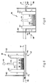
- FIGS. 4 to 8 A further exemplary embodiment of the packaging device according to the invention or of the method according to the invention is shown in FIGS. 4 to 8.
- the structural design of the rotating basket 90 ie with the base plate 92 and the floor arranged underneath, consisting of the two partial floors 98 and 100, is the same as previously described in connection with FIGS. 1 to 3, so that the same reference numerals are used for the same components will.
- the base parts 98, 100 are held by rods 102, which pass through the base plate 92 and are guided in it via slide bearings, which are not shown here.
- the distance between the two facing end faces of the base parts 98, 100, which delimit the space 104, corresponds, as described above, to the width of the film strip 106, which in the exemplary embodiment shown in FIG. 4 is approximately 6 cm.
- the schematic side view of the rotating basket 90 shown in FIGS. 5 to 8 corresponds to that from the direction of the arrow 72 of FIG. 1.
- the angle rails 103 hold the specimens lying on the floor 96 or the partial floor 100 shown in FIGS four vertices of the stack 120 vertically immovable.
- the angle rails 103 are, as described above, displaceable in order to be adapted in each case to the corresponding specimen size or to enable the packaged stack 120 to be ejected after packaging.
- the film strip 106 is guided through the support rollers 114, which, as described above, are horizontally displaceable.
- the lowering movement of the bottom 96 takes place in that a press die 116 is lowered onto the top of the uppermost specimen 110 (see in particular FIG. 4).
- the partial stacking device 31 (see FIG. 1) or its parts 32, 33 can be moved so far along the arrows 34 and 35 from one another that the press ram 116 can be placed on the stack 120 lying in the rotating basket 90.
- the press ram 116 has two parallel rails 117 (see. Extending along the direction of the film strip 106) Fig. 4), which press the stack 120 with the press ram 116 between the rails 117 and the bottom parts 98, 100.
- the rails 117 are spaced apart from one another in such a way that they are at least as far apart as the end faces of the base parts 98 and 100 are from one another. This ensures that the stack 120 does not bend and that, as described below, the area of the top of the top copy 110 is also accessible, which is opposite the area of the bottom of the bottom copy 112 where the latter is opposite the foil strip 106 . This means that the area of the stack 120 around which the film strip 106 is to be placed is again exposed.
- the press ram 116 resting on the uppermost specimen 110 is further delivered, as a result of which the stack 120 is then sunk into the foil strip 106, as described above, and placed around the bottom and the side regions thereof as shown in FIG. 6.
- the press die 116 is lowered until it comes to rest at the level of the weld die 118 (see FIG. 6) arranged on both sides.
- the rods 102 are connected to a return device, not shown here, which gives the rods a tendency to pull the floor upwards.
- This return force is optionally adjustable so that the stack 120 is pressed with a predetermined pressure between the rails 117 and the bottom parts 98, 100.
- the two welding stamps 118 which move in from the side, pull the film strip 106 along on both sides over the top of the stack 120 and meet in the middle of the stack (see FIG. 7). There they weld the two sections of the film strip 106 clamped between the welding punches 118 and separate the loop 76 which is tight around the stack 120 from the rest of the film strip 106. As described above, this then snaps back into the upper horizontal position and the connection point 121 can be seen, as described above.
- the packaged stack 120 can then either be pushed onto a conveyor belt 24, as shown in FIG. 1, or, as can be seen in FIG. 8, also pushed off laterally from the base part 100 or 98, as indicated by the arrow 119 .
- the ram 116 is raised to release the packaged stack 120.
- the rods 102 and their return device are also blocked.
- the floor then returns to the uppermost position just below the base plate 92 and is ready to receive a new partial stack 38 from the partial stacking device 31.
Landscapes
- Engineering & Computer Science (AREA)
- Mechanical Engineering (AREA)
- Basic Packing Technique (AREA)
- Packaging Of Special Articles (AREA)
- Pile Receivers (AREA)
Applications Claiming Priority (2)
| Application Number | Priority Date | Filing Date | Title |
|---|---|---|---|
| DE19873742787 DE3742787A1 (de) | 1987-12-17 | 1987-12-17 | Verfahren und vorrichtung zum verpacken von druckerzeugnissen |
| DE3742787 | 1987-12-17 |
Publications (2)
| Publication Number | Publication Date |
|---|---|
| EP0320797A1 true EP0320797A1 (fr) | 1989-06-21 |
| EP0320797B1 EP0320797B1 (fr) | 1992-08-12 |
Family
ID=6342823
Family Applications (1)
| Application Number | Title | Priority Date | Filing Date |
|---|---|---|---|
| EP88120520A Expired - Lifetime EP0320797B1 (fr) | 1987-12-17 | 1988-12-08 | Dispositif pour emballer des produits d'imprimerie |
Country Status (3)
| Country | Link |
|---|---|
| US (1) | US5353576A (fr) |
| EP (1) | EP0320797B1 (fr) |
| DE (2) | DE3742787A1 (fr) |
Cited By (3)
| Publication number | Priority date | Publication date | Assignee | Title |
|---|---|---|---|---|
| DE19615009A1 (de) * | 1996-04-16 | 1997-10-23 | Smb Schwede Maschinenbau Gmbh | Kreuzleger mit Umreifungsvorrichtung |
| EP0838402A3 (fr) * | 1996-10-23 | 1998-09-02 | Graphic Management Associates, Inc. | Dispositifs et méthodes pour relier et cercler |
| WO2021011978A1 (fr) * | 2019-07-22 | 2021-01-28 | Tgw Logistics Group Gmbh | Dispositif de groupage de marchandises, système de stockage et de préparation des commandes et procédé d'empilement de marchandises et de fixation de l'empilement de marchandises à l'aide d'une bande |
Families Citing this family (32)
| Publication number | Priority date | Publication date | Assignee | Title |
|---|---|---|---|---|
| DE4328604C2 (de) * | 1993-08-25 | 1995-12-07 | Gaemmerler Hagen | Drehbare Stapelkammer in einem Kreuzleger für Druckprodukte |
| DE29507282U1 (de) * | 1995-05-04 | 1995-06-29 | Jagenberg Diana GmbH, 41468 Neuss | Vorrichtung zum Beschicken einer Umreifungsvorrichtung |
| US5803891A (en) * | 1996-02-01 | 1998-09-08 | Moore Business Forms, Inc. | Apparatus of accumulating sheets for a booklet |
| DE19607084B4 (de) * | 1996-02-24 | 2005-10-27 | Smb Schwede Maschinenbau Gmbh | Umreifungsmaschine, insbesondere Kreuzumreifungsmaschine |
| IT1292608B1 (it) * | 1997-06-09 | 1999-02-08 | Gd Spa | Dispositivo e metodo per orientare foglietti o gruppi di foglietti, in particolare banconote. |
| US6179548B1 (en) | 1997-08-21 | 2001-01-30 | Multifold International, Inc. | Folded carton stacking and packing apparatus |
| KR100471125B1 (ko) * | 1997-11-27 | 2005-06-07 | 삼성전자주식회사 | 반도체 패키지 운반용 튜브의 자동 포장 방법 및장치 |
| US6007293A (en) * | 1998-03-20 | 1999-12-28 | Webcrafters, Inc. | Signature bundle inverter |
| EP1008521A3 (fr) * | 1998-12-09 | 2003-09-03 | SIG Pack Systems AG | Dispositif pour alimenter des groupes de produits plats empilés, notemment des biscuits, dans des récipients d'emballage |
| US6192655B1 (en) * | 1999-08-31 | 2001-02-27 | Todd Motion Controls, Inc. | Hosiery manipulation device and method |
| IT1311117B1 (it) * | 1999-11-02 | 2002-02-28 | Gd Spa | Macchina per ordinare e alimentare mazzette di foglietti ad una unita'di formazione di gruppi di mazzette. |
| DE50100700D1 (de) * | 2000-03-29 | 2003-11-06 | Sig Pack Systems Ag Beringen | Vorrichtung zum Befüllen von rohrförmigen Behältern mit einem Stapel von scheibenförmigen Produkten, insbesondere Kartoffelchips |
| US20030041712A1 (en) * | 2000-03-31 | 2003-03-06 | Masao Tsuruta | Apparatus for and method of manufacturing sheets |
| EP1167261B1 (fr) * | 2000-06-30 | 2004-02-04 | Segbert GmbH & Co. Kommanditgesellschaft | Dispositif pour former et aligner des paquets de produits d'imprimerie mobiles empilés |
| DE50108627D1 (de) * | 2000-08-18 | 2006-03-30 | Ferag Ag | Verfahren und vorrichtung zur herstellung von kreuzstapeln |
| DE10045062A1 (de) * | 2000-09-12 | 2002-03-21 | Gaemmerler Ag | Stapelvorrichtung |
| JP4542717B2 (ja) * | 2001-01-12 | 2010-09-15 | 富士フイルム株式会社 | シート集積体生産システム |
| DE10113339A1 (de) * | 2001-03-20 | 2002-09-26 | Koenig & Bauer Ag | Vorrichtungen und ein Verfahren zum Bündeln eines Stapels von blattartigen Gegenständen |
| DE10317948A1 (de) * | 2003-04-17 | 2004-10-28 | Gämmerler AG | Handhabungssystem |
| US6931823B2 (en) * | 2003-08-27 | 2005-08-23 | Johns Manville International, Inc. | Packaging machine and method |
| DE502004008262D1 (de) * | 2004-05-05 | 2008-11-27 | Mueller Martini Holding Ag | Vorrichtung zum Bilden von Stapeln aus Druckprodukten |
| US7243479B2 (en) * | 2005-06-23 | 2007-07-17 | Johns Manville | Apparatus and method for loading a packaging station of an insulation batt packager |
| US7780396B2 (en) * | 2005-10-27 | 2010-08-24 | Graphic Packaging International, Inc. | Automatic carton stacker/collator |
| US7856797B2 (en) * | 2008-04-03 | 2010-12-28 | Arm Automation, Inc. | Automated collector device and methods |
| DE102008029766B4 (de) * | 2008-06-25 | 2013-04-04 | Winkler + Dünnebier Gmbh | Vorrichtung zum Verpacken von flachen Artikeln |
| EP2368826B1 (fr) * | 2010-03-25 | 2013-05-22 | Müller Martini Holding AG | Procédé et dispositif destinés à former des paquets dans un dispositif de formation de paquets |
| DE102013206858B4 (de) * | 2013-04-16 | 2018-06-21 | Andreas Klamm | Verfahren und Vorrichtung zum Banderolieren von Kleinfalzungen |
| JP6162524B2 (ja) * | 2013-07-31 | 2017-07-12 | グローリー株式会社 | 紙葉類結束装置 |
| CN107792432A (zh) * | 2017-08-31 | 2018-03-13 | 芜湖美威包装品有限公司 | 包装泡沫叠放包装装置 |
| TWI636944B (zh) * | 2017-09-14 | 2018-10-01 | 全利機械股份有限公司 | 紙類包裝物的輸送系統及分層堆疊裝置 |
| TWI637893B (zh) * | 2018-03-14 | 2018-10-11 | 矽品精密工業股份有限公司 | 打帶設備及打帶方法 |
| DE102020101506A1 (de) * | 2020-01-23 | 2021-07-29 | MM Engineering GmbH | Vorrichtung und Verfahren zur Durchführung von Verpackungsschritten von flächigen Kartongütern |
Citations (5)
| Publication number | Priority date | Publication date | Assignee | Title |
|---|---|---|---|---|
| DE1223294B (de) * | 1963-09-12 | 1966-08-18 | Printing Machinery Company | Vorrichtung zum Umbaendern von Stapeln blattfoermiger flacher Gegenstaende, wie Etiketten, Faltschachteln u. dgl. |
| WO1981003315A1 (fr) * | 1980-05-13 | 1981-11-26 | C Flensburg | Dispositif pour la mise en liasse de feuilles ou fascicules |
| EP0113874A1 (fr) * | 1983-01-04 | 1984-07-25 | F.H. Schule GmbH | Machine à envelopper et à cercler une pile compressible |
| DE3346168A1 (de) * | 1983-12-21 | 1985-07-04 | Heinz 2359 Henstedt-Ulzburg Walter | Vorrichtung zum bilden verpackungsfaehiger stapel von gegenstaenden |
| EP0243944A1 (fr) * | 1986-04-29 | 1987-11-04 | STAHL GmbH & Co. Maschinenfabrik | Dispositif pour fabriquer des paquets ou des piles de feuilles de papier pliées |
Family Cites Families (16)
| Publication number | Priority date | Publication date | Assignee | Title |
|---|---|---|---|---|
| US2599290A (en) * | 1948-10-23 | 1952-06-03 | Harry D Culver | Stacking device |
| US2741885A (en) * | 1952-12-08 | 1956-04-17 | Gen Mills Inc | Banding with thermoplastic |
| US3343334A (en) * | 1963-02-28 | 1967-09-26 | Journal Company | Method and apparatus fof bundling stacked material |
| NL7314126A (nl) * | 1973-10-15 | 1975-04-17 | Hapa Holland Nv | Inrichting voor het bundelen van vlakke buigzame voorwerpen. |
| US3991542A (en) * | 1974-09-17 | 1976-11-16 | Eastman Kodak Company | Apparatus for banding a stack of articles |
| DE2827540C2 (de) * | 1978-06-23 | 1980-07-31 | Jagenberg-Werke Ag, 4000 Duesseldorf | Stapelvorrichtung für Faltschachteln |
| DE2835308A1 (de) * | 1978-08-11 | 1980-02-14 | Gao Ges Automation Org | Verfahren und vorrichtung zum banderolieren von duennem blattgut |
| US4250692A (en) * | 1978-12-22 | 1981-02-17 | Laurel Bank Machine Co., Ltd. | Apparatus for binding paper sheets |
| US4457656A (en) * | 1981-01-30 | 1984-07-03 | Nolan Systems, Inc. | Stack assembling apparatus and technique |
| CH652675A5 (de) * | 1981-10-22 | 1985-11-29 | De La Rue Giori Sa | Vorrichtung zur automatischen verarbeitung von stapeln druckfrischer wertscheinbogen, insbesondere banknotenbogen, zu buendelpaketen. |
| US4466227A (en) * | 1981-12-24 | 1984-08-21 | H. F. Hanscom & Company, Inc. | Machine for wrapping tape about an article |
| US4547112A (en) * | 1984-01-20 | 1985-10-15 | Rima Enterprises | Signature handling apparatus |
| JPS6127869A (ja) * | 1984-07-13 | 1986-02-07 | Nichiro Kogyo Kk | 折帖印刷物の小束段積み装置 |
| DE8519072U1 (de) * | 1985-07-01 | 1985-08-14 | Henssler, Heiner, Dipl.-Designer (Fh) | Altpapiersammler |
| EP0234444B1 (fr) * | 1986-02-17 | 1990-12-27 | Gunze Limited | Appareil pour manipuler des cahiers avant la reliure |
| US4805383A (en) * | 1988-01-11 | 1989-02-21 | Manville Corporation | Batt packaging machine and method |
-
1987
- 1987-12-17 DE DE19873742787 patent/DE3742787A1/de active Granted
-
1988
- 1988-12-08 DE DE8888120520T patent/DE3873707D1/de not_active Expired - Lifetime
- 1988-12-08 EP EP88120520A patent/EP0320797B1/fr not_active Expired - Lifetime
- 1988-12-12 US US07/283,198 patent/US5353576A/en not_active Expired - Fee Related
Patent Citations (5)
| Publication number | Priority date | Publication date | Assignee | Title |
|---|---|---|---|---|
| DE1223294B (de) * | 1963-09-12 | 1966-08-18 | Printing Machinery Company | Vorrichtung zum Umbaendern von Stapeln blattfoermiger flacher Gegenstaende, wie Etiketten, Faltschachteln u. dgl. |
| WO1981003315A1 (fr) * | 1980-05-13 | 1981-11-26 | C Flensburg | Dispositif pour la mise en liasse de feuilles ou fascicules |
| EP0113874A1 (fr) * | 1983-01-04 | 1984-07-25 | F.H. Schule GmbH | Machine à envelopper et à cercler une pile compressible |
| DE3346168A1 (de) * | 1983-12-21 | 1985-07-04 | Heinz 2359 Henstedt-Ulzburg Walter | Vorrichtung zum bilden verpackungsfaehiger stapel von gegenstaenden |
| EP0243944A1 (fr) * | 1986-04-29 | 1987-11-04 | STAHL GmbH & Co. Maschinenfabrik | Dispositif pour fabriquer des paquets ou des piles de feuilles de papier pliées |
Cited By (7)
| Publication number | Priority date | Publication date | Assignee | Title |
|---|---|---|---|---|
| DE19615009A1 (de) * | 1996-04-16 | 1997-10-23 | Smb Schwede Maschinenbau Gmbh | Kreuzleger mit Umreifungsvorrichtung |
| DE19615009B4 (de) * | 1996-04-16 | 2005-09-29 | Smb Schwede Maschinenbau Gmbh | Kreuzleger mit Umreifungsvorrichtung |
| EP0838402A3 (fr) * | 1996-10-23 | 1998-09-02 | Graphic Management Associates, Inc. | Dispositifs et méthodes pour relier et cercler |
| EP1394046A1 (fr) * | 1996-10-23 | 2004-03-03 | Graphic Management Associates, Inc. | Dispositifs et méthodes pour relier et cercler |
| WO2021011978A1 (fr) * | 2019-07-22 | 2021-01-28 | Tgw Logistics Group Gmbh | Dispositif de groupage de marchandises, système de stockage et de préparation des commandes et procédé d'empilement de marchandises et de fixation de l'empilement de marchandises à l'aide d'une bande |
| AT522858A1 (de) * | 2019-07-22 | 2021-02-15 | Tgw Logistics Group Gmbh | Warenbündelungsvorrichtung, Lager- und Kommissioniersystem und Verfahren zum Stapeln von Waren und Sichern des Warenstapels mit einem Band |
| US12409964B2 (en) | 2019-07-22 | 2025-09-09 | Tgw Logistics Gmbh | Article bundling device, picking system and method for stacking articles and securing the stack of articles with a band |
Also Published As
| Publication number | Publication date |
|---|---|
| US5353576A (en) | 1994-10-11 |
| DE3742787C2 (fr) | 1990-05-10 |
| EP0320797B1 (fr) | 1992-08-12 |
| DE3742787A1 (de) | 1989-06-29 |
| DE3873707D1 (de) | 1992-09-17 |
Similar Documents
| Publication | Publication Date | Title |
|---|---|---|
| EP0320797B1 (fr) | Dispositif pour emballer des produits d'imprimerie | |
| DE3705169C2 (fr) | ||
| DE69718744T2 (de) | Maschine zum Herstellen kissenartiger Verpackungen | |
| DE3906922C2 (fr) | ||
| DE2827540B1 (de) | Stapelvorrichtung fuer Faltschachteln | |
| EP0421148A2 (fr) | Dispositif et procédé pour transporter et empiler des pièces découpées pour la production des paquets de cigarettes | |
| EP0563642A2 (fr) | Machine pour encartonner | |
| EP0243944A1 (fr) | Dispositif pour fabriquer des paquets ou des piles de feuilles de papier pliées | |
| EP0640529A1 (fr) | Dispositif pour banderoler des produits d'imprimerie | |
| DE2356877C2 (de) | Vorrichtung zum Bilden verpackungsfähiger Gruppen von Beuteln oder Säcken | |
| DE3432517C2 (de) | Vorrichtung zum Umlegen der einen gefüllten Sack seitlich überragenden Fahnen auf die mit Klebstoffstreifen versehene Sackoberseite | |
| EP4291519B1 (fr) | Procédé pour déplacer une pile de produits plats et dispositif de déplacement pour déplacer une pile de produits plats | |
| DE4030643C2 (fr) | ||
| DE19943800A1 (de) | Verfahren und Vorrichtung zum Stapeln von Papierprodukten | |
| DE19822998C2 (de) | Vorrichtung zum Einbringen von gestapelten Kuverts in einen Transportkasten | |
| DE68919957T2 (de) | Vorrichtung zum Aufbewahren und Zuführen von bogenförmigem Material. | |
| DE2949896C2 (de) | Vorrichtung zum Stapeln von aus einer Faltschachtelklebemaschine kommenden Faltschachteln | |
| DE2541488A1 (de) | Vorrichtung zum automatischen paketieren und verpacken von papierstapeln und aehnlichem | |
| DE2545813C2 (de) | Vorrichtung zum Verpacken flacher Werkstücke | |
| DE2356126A1 (de) | Verfahren und vorrichtung zum herstellen von stapeln aus um zwei querfalten gefalteten flachliegenden beuteln oder saecken | |
| DE4415605C2 (de) | Vorrichtung zum Verschließen eines flexiblen Verpackungselementes zur Verpackung von stapelbarem, insbesondere blattförmigem Gut | |
| DE2731900A1 (de) | Vorrichtung und verfahren zum verpacken von einheiten in behaeltern | |
| EP0563649B1 (fr) | Procédé et appareil pour former un enveloppement fermé autour d'un article | |
| DE2109265C3 (de) | Vorrichtung zum Umwickeln von aus flachen Gegenständen gebildeten Stapeln mit Hüllmaterial | |
| DE2646919A1 (de) | Vorrichtung zum umwickeln eines stapels von zuschnitten mit wickelmaterial |
Legal Events
| Date | Code | Title | Description |
|---|---|---|---|
| PUAI | Public reference made under article 153(3) epc to a published international application that has entered the european phase |
Free format text: ORIGINAL CODE: 0009012 |
|
| AK | Designated contracting states |
Kind code of ref document: A1 Designated state(s): CH DE FR GB IT LI NL |
|
| 17P | Request for examination filed |
Effective date: 19890606 |
|
| 17Q | First examination report despatched |
Effective date: 19910430 |
|
| GRAA | (expected) grant |
Free format text: ORIGINAL CODE: 0009210 |
|
| AK | Designated contracting states |
Kind code of ref document: B1 Designated state(s): CH DE FR GB IT LI NL |
|
| PG25 | Lapsed in a contracting state [announced via postgrant information from national office to epo] |
Ref country code: NL Effective date: 19920812 Ref country code: IT Free format text: LAPSE BECAUSE OF FAILURE TO SUBMIT A TRANSLATION OF THE DESCRIPTION OR TO PAY THE FEE WITHIN THE PRE;WARNING: LAPSES OF ITALIAN PATENTS WITH EFFECTIVE DATE BEFORE 2007 MAY HAVE OCCURRED AT ANY TIME BEFORE 2007. THE CORRECT EFFECTIVE DATE MAY BE DIFFERENT FROM THE ONE RECORDED.SCRIBED TIME-LIMIT Effective date: 19920812 |
|
| REF | Corresponds to: |
Ref document number: 3873707 Country of ref document: DE Date of ref document: 19920917 |
|
| GBT | Gb: translation of ep patent filed (gb section 77(6)(a)/1977) | ||
| ET | Fr: translation filed | ||
| NLV1 | Nl: lapsed or annulled due to failure to fulfill the requirements of art. 29p and 29m of the patents act | ||
| PLBE | No opposition filed within time limit |
Free format text: ORIGINAL CODE: 0009261 |
|
| STAA | Information on the status of an ep patent application or granted ep patent |
Free format text: STATUS: NO OPPOSITION FILED WITHIN TIME LIMIT |
|
| 26N | No opposition filed | ||
| PGFP | Annual fee paid to national office [announced via postgrant information from national office to epo] |
Ref country code: FR Payment date: 19951116 Year of fee payment: 8 Ref country code: GB Payment date: 19951116 Year of fee payment: 8 |
|
| PGFP | Annual fee paid to national office [announced via postgrant information from national office to epo] |
Ref country code: CH Payment date: 19951127 Year of fee payment: 8 |
|
| PGFP | Annual fee paid to national office [announced via postgrant information from national office to epo] |
Ref country code: DE Payment date: 19960202 Year of fee payment: 8 |
|
| PG25 | Lapsed in a contracting state [announced via postgrant information from national office to epo] |
Ref country code: GB Effective date: 19961208 |
|
| PG25 | Lapsed in a contracting state [announced via postgrant information from national office to epo] |
Ref country code: LI Effective date: 19961231 Ref country code: CH Effective date: 19961231 |
|
| GBPC | Gb: european patent ceased through non-payment of renewal fee |
Effective date: 19961208 |
|
| REG | Reference to a national code |
Ref country code: CH Ref legal event code: PL |
|
| PG25 | Lapsed in a contracting state [announced via postgrant information from national office to epo] |
Ref country code: FR Effective date: 19970829 |
|
| PG25 | Lapsed in a contracting state [announced via postgrant information from national office to epo] |
Ref country code: DE Effective date: 19970902 |
|
| REG | Reference to a national code |
Ref country code: FR Ref legal event code: ST |