EP0320880A2 - Verfahren zur Feststellung der Bildnummern eines photographischen Filmes - Google Patents
Verfahren zur Feststellung der Bildnummern eines photographischen Filmes Download PDFInfo
- Publication number
- EP0320880A2 EP0320880A2 EP88120816A EP88120816A EP0320880A2 EP 0320880 A2 EP0320880 A2 EP 0320880A2 EP 88120816 A EP88120816 A EP 88120816A EP 88120816 A EP88120816 A EP 88120816A EP 0320880 A2 EP0320880 A2 EP 0320880A2
- Authority
- EP
- European Patent Office
- Prior art keywords
- frame
- film
- bar code
- picture frame
- photographic film
- Prior art date
- Legal status (The legal status is an assumption and is not a legal conclusion. Google has not performed a legal analysis and makes no representation as to the accuracy of the status listed.)
- Granted
Links
- 238000000034 method Methods 0.000 title claims description 46
- 238000007639 printing Methods 0.000 claims abstract description 86
- 238000009432 framing Methods 0.000 claims abstract description 82
- 238000005259 measurement Methods 0.000 claims abstract description 7
- 238000001514 detection method Methods 0.000 claims description 17
- 230000015654 memory Effects 0.000 description 64
- 238000012937 correction Methods 0.000 description 10
- 238000007689 inspection Methods 0.000 description 9
- 239000011295 pitch Substances 0.000 description 8
- 230000008569 process Effects 0.000 description 6
- 238000010586 diagram Methods 0.000 description 5
- 238000002834 transmittance Methods 0.000 description 5
- 238000011161 development Methods 0.000 description 3
- 238000003708 edge detection Methods 0.000 description 3
- 230000008859 change Effects 0.000 description 2
- 238000006243 chemical reaction Methods 0.000 description 2
- 230000006872 improvement Effects 0.000 description 2
- 238000004519 manufacturing process Methods 0.000 description 2
- 238000012986 modification Methods 0.000 description 2
- 230000004048 modification Effects 0.000 description 2
- 238000012015 optical character recognition Methods 0.000 description 2
- 238000012545 processing Methods 0.000 description 2
- 229910002056 binary alloy Inorganic materials 0.000 description 1
- 230000005540 biological transmission Effects 0.000 description 1
- 239000003086 colorant Substances 0.000 description 1
- 230000000295 complement effect Effects 0.000 description 1
- 238000005520 cutting process Methods 0.000 description 1
- 238000009792 diffusion process Methods 0.000 description 1
- 230000000694 effects Effects 0.000 description 1
- 238000005286 illumination Methods 0.000 description 1
- 230000000977 initiatory effect Effects 0.000 description 1
- 238000003780 insertion Methods 0.000 description 1
- 230000037431 insertion Effects 0.000 description 1
- 239000004973 liquid crystal related substance Substances 0.000 description 1
- 239000011159 matrix material Substances 0.000 description 1
- 230000003287 optical effect Effects 0.000 description 1
- 230000000737 periodic effect Effects 0.000 description 1
- 230000002093 peripheral effect Effects 0.000 description 1
- 230000002035 prolonged effect Effects 0.000 description 1
- 238000003860 storage Methods 0.000 description 1
- 230000001360 synchronised effect Effects 0.000 description 1
Images







Classifications
-
- G—PHYSICS
- G03—PHOTOGRAPHY; CINEMATOGRAPHY; ANALOGOUS TECHNIQUES USING WAVES OTHER THAN OPTICAL WAVES; ELECTROGRAPHY; HOLOGRAPHY
- G03B—APPARATUS OR ARRANGEMENTS FOR TAKING PHOTOGRAPHS OR FOR PROJECTING OR VIEWING THEM; APPARATUS OR ARRANGEMENTS EMPLOYING ANALOGOUS TECHNIQUES USING WAVES OTHER THAN OPTICAL WAVES; ACCESSORIES THEREFOR
- G03B27/00—Photographic printing apparatus
- G03B27/32—Projection printing apparatus, e.g. enlarger, copying camera
- G03B27/46—Projection printing apparatus, e.g. enlarger, copying camera for automatic sequential copying of different originals, e.g. enlargers, roll film printers
- G03B27/462—Projection printing apparatus, e.g. enlarger, copying camera for automatic sequential copying of different originals, e.g. enlargers, roll film printers in enlargers, e.g. roll film printers
-
- G—PHYSICS
- G03—PHOTOGRAPHY; CINEMATOGRAPHY; ANALOGOUS TECHNIQUES USING WAVES OTHER THAN OPTICAL WAVES; ELECTROGRAPHY; HOLOGRAPHY
- G03B—APPARATUS OR ARRANGEMENTS FOR TAKING PHOTOGRAPHS OR FOR PROJECTING OR VIEWING THEM; APPARATUS OR ARRANGEMENTS EMPLOYING ANALOGOUS TECHNIQUES USING WAVES OTHER THAN OPTICAL WAVES; ACCESSORIES THEREFOR
- G03B27/00—Photographic printing apparatus
- G03B27/32—Projection printing apparatus, e.g. enlarger, copying camera
- G03B27/52—Details
- G03B27/62—Holders for the original
- G03B27/6271—Holders for the original in enlargers
- G03B27/6285—Handling strips
Definitions
- the present invention relates to a method of identifying a frame number of a picture frame of a photographic film, and more particularly to a method of identifying a frame number of a photographic film placed in a film framing mask, which method is used in a photographic printer, a negative film inspection apparatus, a numbering apparatus for printing frame numbers on prints or the like.
- Disk films now available have a circular arrangement of exposable frames at regular angular intervals or spacings, each exposable frame being attached with a decimal number and a binary bar code both of which are latent image and represent a serial frame number.
- the binary bar code is read with a bar code sensor or bar code reader to print a number in decimal figure representative of the serial frame number of each eaxposed frame of the disk film on the back surface of a print.
- required operation for the disk film printing system is only to enter data on the serial frame number of the picture frame to be printed and the number of extra prints to be made from the picture frame.
- the disk film printing system reads binary codes based on the entered data to identify the serial frame number of picture frame and then places automatically a picture frame having the specified serial frame number at a printing station. The disk film printing system, thereafter, provides automatically prints as many as requested.
- an apparatus is known being enabled to print the frame number of a picture frame on the print at the time of first printing.
- a mark is recorded on the center line of the first picture frame of a negative film and, thereafter, the frame number of each picture frame at the printing station is specified based on a advanced length of the negative film after detection of the mark.
- the specified frame number is then printed either on the peripheral margin of a print of the picture frame or on the back surface of the print by using a number printer.
- an apparatus such as disclosed for example, in Japanese Unexamined Patent Publication No.52-111,718 is used.
- the frame number of a picture frame to be printed is read with an optical character reader, such as an image sensor, to identify the requested picture frame and to place the picture frame having the identified frame number in position in the film framing mask at the printing station in order to make prints as many as requested.
- an optical character reader such as an image sensor
- a problem associated with the above described apparatus is the necessity of recording a start mark or of providing a complicated optical character reader.
- Such a problem may be solved by way of providing latent image bar codes indicating the frame numbers which are optically printed in manufacturing a film aside the respective exposable frames of the negative film in the similar manner as manufacturing the above noted disk films.
- a bar code can be read with an optical sensor disposed on the passage of the negative film to identify the frame number of a picture frame positioned in the film framing mask at the printing station.
- an object of the present invention to provide a method of identifying the frame number of a picture frame of a photographic film which is placed in position in a film framing mask at the printing station when a position error between the frame number bar code and the picture frame.
- the present invention provides a method of identifying a frame number of a picture frame of a photographic film having a series of picture frames each of which is accompanied with a decimal number and a bar codes both being representatives of the frame number and is placed in a film framing mask at a printing station.
- the identification of frame number can be performed by sequentially effecting the steps of; beginning to measure an advanced distance of the photographic film at the detection of a bar code so as to detect a moved distance of the bar code or decimal number from the bar code sensor; locating the picture frame to be printed in the film framing mask at the printing station; and drawing a frame number represented by a decimal number or bar code whose moved distance is within a predetermined range of distances, thereby identifying the picture frame in the film framing mask to have the drawn frame number.
- an advanced length of the frame number bar code or the location of a frame number bar code is detected by counting either drive pulses applied to a film advancing motor or output pulses from an encoder cooperated with a roller driven following a film advanced by a pulse motor.
- the film is advanced by a certain length each time and is placed to position a picture frame to be printed in the film framing mask at the printing station.
- a frame number which is within a distance ranges on both sides of the center of the film framing mask is drawn and specified as to be the frame number of the picture frame positioned in the film framing mask at the printing station.
- side notches formed in a side margin of a film one to each picture frame to be printed are detected with a notch sensor at the center of the film framing mask to position the film in the film framing mask at the printing station.
- the picture frame to be printed is detected with an picture image sensor to position the picture frame in the film framing mask at the printing station.
- the image sensor which detects front and rear edges of the picture frame, can takes any desired type such as an image area sensor, a line sensor or the like well known in the art.
- the image sensor is disposed above and before or after the film framing mask to sight a picture frame in the mask if taking the type of image area sensor or perpendicularly to and before the passage of a film to detect an edge of the picture frame.
- an image sensor provided to detect densities of the respective pixels of the picture frame can be commonly used.
- a picture frame of the photographic film strip to be printed is placed in position at the printing station.
- sevral means for positioning a picture frame at the printing station such as the notch detector, picture frame detector, edge sensor and the like, are incorporated and are selected for use in order of a predetermined priority.
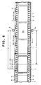
- a negative film 2 viewed from the back.
- a bar code sensor 6 disposed near and after the film framing mask 7 at a printing station of a printer for reading bar codes.
- a line image sensor is preferably used as the bar code sensor 6.
- other suitable sensors can be used in dependence upon types of bar code systems.
- the negative film 2 has bar codes 3 representing frame numbers (which are hereinunder referred to as frame number bar codes) in one side margin thereof and DX bar codes 4 representing a photographic character of the negative film 2.
- frame numbers representing frame numbers (which are hereinunder referred to as frame number bar codes) in one side margin thereof
- DX bar codes 4 representing a photographic character of the negative film 2.
- frame numbers in decimal figures in both of the side margins thereof.
- Each picture frame is attached with two same frame numbers 5 in each side margin, one of which accompanies an reference character of "A".
- the presence or absence of a code bar of the frame number bar code can be detected by the bar code sensor 6 during the advancement of the negative film 2.
- This bar code sensor 6 can be a line sensor disposed along a direction of the advancement of film or sensor unit having two light receiving elements spaced apart by the minimum width of code bar.
- the two element sensor unit detects the width of code bar by judging whether the two light receiving elements provide outputs of a same level. If only one light receiving element is used, the width of code bar can be detected based on an output therefrom with reference to the speed of advancement of the negative film 2.
- the frame number bar code 3 includes an entry code bar in transverse alignment with the entry code bar of the DX code 4. Therefore, it is possible to read the data on a frame number by detecting the presence of a bar code in the clock truck of the DX code 4.
- a DX sensor for reading the DX code 4 is disposed in the passage of the negative film 2. To this end, two sensors, each being consisting of four light receiving units arranged in two rows and two columns, can be mounted on both sides of the passage of the negative film 2 and on one side of the film framing mask 7, or four sensors can be mounted, two on each side of the film framing mask 7.
- Fig. 2 shows an example of a frame number bar code.
- various bar code systems are known in various fields; for example, "Interleaved 2 of 5", "Industrial 2 of 5", and "Code 3 of 9” as a bi-level bar code system, and "UPC” and the like as a multi-level bar code system. Any one of these bar code systems can be used in this invention.
- "Code 3 of 9” is used for the five-bit data array 3a.
- entry and exit zones 3b and 3c are provided on the opposite sides of the data zone 3a, respectively, to allow the identification of the first and last bit bar of the data zone 3a.
- “Code 3 of 9” consists of wide and narrow bars and blanks alternately arranged; the wider bar representing a binary number in 1's and the narrower bar representing a binary number 0's. As well known in the art, "Code 3 of 9” does not represent a binary number so that odd or even of a decimal number cannot be determined from the last bit bar.
- the frame number bar code 3 of the data zone 3a shown in Fig. 2 represents "001001100" in the binary system and means "24” in the decimal system.
- the correspondence between frame number bar codes (indicated by decimal number for convenience sake) and frame numbers is given in Table I by way of example. TABLE I Frame number bar code (Decimal Number) Frame number 0 S 1 SA 2 1 3 1A 4 2 5 2A . . . . 24 12 25 12A . . . . 28 14 29 14A . . . . . . 73 36A
- Both a length A of the frame number bar code 3 and a distance B from the center of the frame number 5 to the start bit 3b are predetermined and constant. Therefore, a distance C between the frame number 5 and the bar cord of the array is constant. Furthermore, the pitches between each two adjacent frame number bar code 3 and between each two adjacent frame numbers 5 are constant, respectively, and take a value D .
- the measurement of the negative film 2 is started to detect the length of advancement of the negative film 2 simultaneously with the storing of data on the read frame number bar code 3, so that a distance by which the frame number bar code 3 is displaced from the position of the bar code sensor 6.
- the measurement of advanced length of the negative film 2 is effected referring either to the entry bar 3b or to the exit bar 3c. Therefore, the advanced length of the negative film 2 can be known by adding to a detected length the distance B in the case of using the entry bar 3b or the distance C in the case of using the exit bar 3c.
- the distance L between the bar code sensor 6 and the center of the film framing mask 7 is designed to be a half of the two times and half of the length of picture frame, locations of five frame number bar codes can be detected simultaneously.
- a frame number can be identified by detecting two of the five frame number bar codes 3 which are within a distance L3 between the limits defined by a distance L0 from the center of the film framing mask 7. This can be effected by detecting the frame number bar codes within the distance L2 and out of the distance L1.
- the distance L3 is to be slightly longer than both a unit pitch at which the frame number 5 is disposed in the margins of the negative film 2 and shorter than the length of picture frame. If two frame numbers are detected simultaneously, either one without the indication "A" or one whose advanced length is more close to the length L than the other is selected. If the distance L3 is made equal to the length of picture frame, it is necessary to change the length L3 according to the sizes of picture frames; half size frame and full size frame.
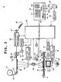
- a photographic color printer with which a method of specifying frame numbers of film according to the present invention is applied.
- Each color filter 11, 12, 13 is controllably insertable independently of the other two between an illumination lamp 10 and a mixing box 14 which comprises a square hollow tube having inner mirrored walls 14a and top and bottom diffusion plates 14b.
- the white light from the lamp 10 passes through the color filters 11, 12 or 13 to regulate each color component of the white light into the mixing box14 and is diffused thereby.
- the diffused light after passing through a color negative film 2 placed between a film holder 17 and a film framing mask 7 so as to be held flat in the printing station, is focussed on a color photographic paper 37 by means of a printing lens 36 to create a latent image of the negative film 2 under the control of a shutter 39 which is controlled by a shutter controller 38 to open and close.
- the negative film 2 is advanced from the left to the right relative to the printing station during film inspection, and from the right to the left during printing, respectively, by means of pairs of feed rollers 19 and 20 disposed on both sides of the printing station.
- the feed rollers 19 and 20 are cooperatively rotated in the normal or reverse direction by a pulse motor 23 through chains or the like.
- the film framing mask 7 is disposed over the film holder 17 at the printing station to press down the negative film 18 against the film holder 17 and maintain it flat.
- the film framing mask 7 has a framing aperture 7a formed therein to define an image area corresponding in size to the picture frame 2a of the negative film, as well known.
- the film framing mask 7 is lifted up and down by a solenoid (not shown) to allow the film 2 to move and to press the film 18 against the film holder 17 while it is inspected or printed.
- the bar code sensor 6 is disposed after the feed rollers 20.
- An image sensor 30 constructed of a lens 32 and an image area sensor 33 is disposed obliquely above the printing station to measure three color components of the transmitted light from each point of the negative image of the picture frame of the negative film 2 placed in position at the printing station.
- the printing lens 36 is disposed above the printing station to project a negative image of each picture frame of the negative film 2 onto the photographic paper 37.
- a framing mask 40 is disposed between the printing lens 36 and the photographic paper 37.
- the photographic paper 37 is withdrawn a roll of photographic paper 41 by one picture frame, and advanced by means of a guide roller 40 and a pair of rollers 44 driven by a pulse motor 43.
- a cutter 45 is provided after the framing mask 40 to cut the photographic paper 37 exposed to print strips each including a predetermined number of picture frames.
- the paper strip is sent to a photographic processor 46 where it is subjected to photographic processing, cut into individual prints by a cutter 47 and delivered into a tray 48.
- a number printer 50 actuated printing signals from the controller 35 is disposed just after the exposure position to print frame numbers on the back of the photographic paper 37 after exposure.
- the frame number is printed, for example, in the form of a dot pattern.
- a character printing unit such as having a liquid crystal panel, a light emission diode array or the like can be used to print frame numbers of, for example, dot pattern, in one side white margin of the photographic paper simultaneously with negative image printing.
- a character printing apparatus can be provided in addition to the photographic printing apparatus, which character printing apparatus reads and store frame numbers in a floppy disk or the like. The floppy disk and the developed photographic paper are set in the character printing apparatus to print the frame numbers on the developed photographic paper. Then, the photographic paper is cut into the respective prints.
- the direction and the number of rotations of the pulse motors 23 and 43 are controlled by means of the drivers 51 and 52, respectively, under the control of the controller 35.
- the controller 35 mainly consists of a microcomputer controls the filter controller 15, the shutter controller 38 and other necessary elements, and also an exposure based on the large area transmittance density of each picture frame.
- a keyboard 53 is provided with a fine adjustment key 54 for acurately positioning the negative film 2, a pass key 55 for passing over a picture frame which is not needed to print, a print start key 56 for initiating the printing process, a correction keys 57 and 58 for entering correction data regarding density and color, respectively, an alphanumeric key 59.
- the fine adjustment key 54 includes two keys 54a and 54b for the advancement of the negative film back and forth, respectively.
- Fig. 4 shows details of an essential part of the controller 35, for use in reading and printing a frame number.
- the negative film 18 is printed with the frame number bar code 3 in one side margin thereof, and the DX code 4 on the other side margin thereof.
- the frame number 5 is printed in both side margins of the film 18.
- the frame number bar code 3 is read with the bar code sensor 6 and converted into binary numerical data with a decoder 62, which data are stored in a memory 63.
- the memory 63 has two memory sections, each having, for example, five memories 64a - 64e, 65a - 65e for storing five frame numbers and the numbers of drive pulses corresponding the frame numbers.
- the respective frame number memories 64a - 64e renew their binary numerical data with the binary numerical data stored in the adjacent memories prior to and every time storing a new binary numerical data in the memory 64a.
- the respective drive pulse number memories 65a - 65e store the number of pulses needed to move the negative film to detect the corresponding frame numbers. The data stored in the memory is changed by an increment of one every time the driver 51 receives one driving pulse.
- the drive pulse number memories 65a - 65b therefore constitute frame number counters. Since the drive pulse number memories, in this embodiment, start to store or count drive pulses upon the bar code sensor 6 detects the exit bar 3c, the drive number memories 65a - 65e are peset to the number of pulses corresponding to the length C shown in Fig. 2 and then change the counted numbers by increment of one. It is of course that the data of each drive pulse number memory 65 is shifted into upper memory with the shift in the frame number memory 64.
- each of the memory sections 64 and 65 can be permitted to have only one memory, for example the memory 65a, 65a.
- the latest binary numerical data and the number of drive pulses corresponding to the binary numerical data are stored in the memories 64a and 65a, respectively.
- the data in the memory 65a is increasingly renewed by the number of drive pulse corresponding to the pitch at which the frame number bar code 3 is arranged and the data in the memory 64a is changed by increment of one to detect a frame number close to the film framing mask 7.
- a frame identifying section 66 retrieves the binary numerical data corresponding the number of drive pulses within a certain range of numbers of driving pulses from the memory 63 when the picture frame 2a of the negative film 2 is placed in the printing station and then writes it in a memory 67.
- the binary numerical data stored in the memory 67 is decoded by a decoder 68 and translated or decoded into a frame number. According to the translated or decoded frame number, the number printer 50 prints the frame number on the back surface of the exposed color photographic paper 37 advanced to the number printer 50.
- a motor control circuit 70 provides a predetermined number of drive pulses upon starting or after printing and sends them to the drive pulse number memory section 65a - 65e and the driver 51.
- the driver 51 controls the pulse motor 23 to rotate through a certain number of revolutions so as to advance the negative film 2 by a certain distance. Even when the fine adjusting key 54 is operated, the motor control circuit 70 provides divided drive pulses to cause the pulse motor 23 to rotate slowly.
- the memories 65a - 65e count up or down the drive pulses thus provided according to the directions of rotation of the pulse motor 23.
- the drive pulses applied to the pulse motor 23 are counted and the pulse number 65a stores the counted number of the drive pulses while the frame number memory 64 stores a binary numerical data into which the frame number bar code 3 thus read is translated or decoded by the decoder 62.
- This counted number stored in the memory 65a is changed and renewed by increment of one every time the driver 51 receives one drive pulse
- the binary numerical data in the frame number memory 64a is shifted into the upper one, namely the frame number memory 64b and simultaneosly the number of drive pulses in the drive pulse number memory 65a is shifted into upper one, namely the drive pulse number memory 65b.
- the memory 65b continues to count drive pulses adding to the shifted number of drive pulses.
- the memories 64a memories the number of driving pulses corresponding to the binary numerical data. In the same manner, the shifting and renewing of binary numerical data and the drive pulse counting are effected.
- the pulse motor 23 stops its rotation to suspend advancement of the negative film 2. Thereafter, the negative film 2 is examined to place the picture frame 2a in position in the film framing mask 7. If in fact the negative film 2 is out of position, the fine adjusting key 54 is operated to correct the negative film 2 in position so as to place the picture frame 2a properly in the film framing mask 2. Responding to the operation of the find adjusting key 54, the motor control circuit 70 provided a direction signal indicating a direction in which the pulse motor 23 is to rotate and drive pulses.
- the pulse motor 23 rotates slowly in the direction indicated by an arrow in which the fine adjusting key 54 is pushed, so as to move the negative film forwardly or backwardly.
- Each of the drive pulse number counter 65a - 65b increment or decrement by the drive pulses provided as a result of the operation of the fine adjusting key 54.
- the negative film 2 at the printing station is observed to determine whether the picture frame 2a of the negative film 2 is to be printed or not and whether the picture frame 2a of the negative film 2 may produce a subject failure in its print. If no print of the picture frame 2a is needed due to, for example, an out-of-focus image, the pass key 55 is operated to advance the negative film 2a so as to replace the picture frame 2a with another one. If it is expected that a print made from the picture frame 2a will be accompanied with a subject failure and therefore will have poor color density and/or color balance, then the color and density correction keys 57 and 58 are operated to manually enter exposure correction data.
- the image sensor 30 measures the negative image of the picture frame 2a to detect data of a large area transmittance density, maximum and minimum density for each color and each data is send to the controller 35.
- the controller 35 an exposure for the picture frame 2a is calculated using the data detected automatically and the exposure correction data manually inputted.
- the filter controller 17 controls the filters 11 - 13, independently and the lamp 10 is excited to emit light at its full rate for a predetermined time.
- the shutter controller 38 controls the shutter 39 to open for an appropriate time, so as to expose the photographic paper 37.
- the frame identifying section 66 selects binary numerical data in one of the memories 64a - 64e corresponding to one of memories 65a - 65e whose count of drive pulses is within certain limits and sends the binary numerical data to the memory 67. If the negative film 2 has 35 mm full size frames and there are two binary numerical data within the certain limits, the memory 67 selects and stores binary numerical data not including the indication "A". On the other hand, if the negative film 2 has 35 mm half size frames and there are two binary numerical data within the certain limits, the memory 67 stores both of the two binary numerical data. The controller 35 then cause the pulse motor 43 to rotate, withdrawing the photographic paper 37 by one picture frame to place the unexposed portion in position at the exposure station.
- the controller 35 reads out the binary numerical data from the memory 67 and sends it to the decoder 68 to translate into data of frame number with reference to Table I and sends it to the number printer 50.
- the number printer 50 drives the printing head in accordance with the inputted data of frame number to print a frame number on the back surface of the print of the first picture frame.
- Each picture frame is printed in the similar manner as described above.
- the cutter 45 operates to cut the exposed portion of the photographic paper 37 and sends it to the photographic processor 46.
- the exposed, cut-off photographic paper is then subjected to the photographic processing at this processor 46 and, thereafter, cut into strips of picture frames to be ejected out into the tray 48.
- FIG. 6 showing still another embodiment of the present invention which is applied to the color printer shown in Fig. 3.
- a particular feature of this embodiment is to identify a frame number of a picture frame of a negative film with side notches in position at a printing station. By detecting a side notch of the negative film at the center of the film framing mask with a notch sensor, the negative film is stopped.
- a frame number of the picture frame at the printing station is specified by a frame number existing within predetermined limits defined based on a distance between the bar coded sensor and the center of the film framing mask.
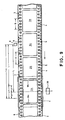
- a negative film 2 is formed with semi-circular notches 1, one for each picture frame which is to be printed.
- the notch 1 is formed in the side margin where the DX bar code 4 is printed and located at the center of the picture frame of the negative film 2.
- a notch sensor 90 to detect the notch 1.
- the notch sensor 90 is at the same distance L as but opposite to the bar code sensor 6 relative to the negative film 2.
- These bar code sensor 6 and notch sensor 90 may be located at different distances from the center of the film framing mask 7.
- the notch sensor 90 detects the notch 1 to start measurement of the length of advancing negative film 2.
- the negative film 2 when advanced by a length equal to the distance between the notch sensor 90 and the center of the film framing mask 7, is stopped to place the picture frame 2a accompanied with a notch 1 in position in the film framing mask 7 at the printing station.
- advanced distances of three notches 1 are measured at once and the negative film 2 is, therefore, continually advanced by a length equal to the distance between the two adjacent notches 1.
- the frame number of the picture frame 2a at the printing station can be specified by detecting two of the five frame number bar codes 3 which are within a distance L3 between the limits defined by a distance L0 from the center of the film framing mask 7. This can be effected by detecting the frame number bar codes within the distance L2 and out of the distance L1.
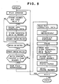
- Fig. 7 shows details of an essential part of the controller 35 for use in identifying and printing frame numbers.
- the number printer 50 is actuated in the same manner as described in connection with the embodiment in Fig. 4.
- the notch sensor 90 detects a notch 1 to provide a notch signal and sends it to notch counter means 81 through a selector 80.
- the notch counter means 81 includes three counters 81a - 81c which are selectively activated by the selector 80 to count drive pulses.
- Data on the number of drive pulses counted by the counters 81a - 81c are transferred to a comparator 82 to be compared with data on numbers of drive pulses corresponding to a distance L between the center of the film framing mask 7 and the notch sensor 90 stored in a memory 83.
- the comparator 82 provides a coincident signal and sends it to the reset-terminal R of a flip-flop 84 so as to thereby reset the flip-flop 84.
- the output terminal Q changes its output signal level to high "L”, changing output signal levels of OR and AND gates 85 and 86 to low “L”, respectively. Consequently the AND gate 86 shuts off drive pulses to pass therethrough to stop the pulse motor 23, stopping the negative film 2.
- the notch 1 attached to the picture frame 2a to be printed is located at the center of the film framing mask 7.
- a direction signal indicating a direction in which the pulse motor 23 is to be rotated is sent to driver 51 though the OR gate 87 and to the OR gate 85.
- the AND gate 86 opens to pass drive pulses, driving the pulse motor 23 in the direction according to the direction signal sent thereto so as to advance manually the negative film 2.
- the pulse motor 23 rotates in the normal direction to advance the negative film 2 forwardly when the OR gate 87 provides a high level output "H" and, on the other hand, in the reverse direction to advance backwardly when the OR gate 87 provides a low level output "L". Since the OR gate 87 is connected to the flip-flop 84 at the Q terminal, the pulse motor 23 rotates in the normal direction at the end of printing of each picture frame.
- the frame number bar code signals are sent to the decoder 62 and are translated or decoded into binary numerical data therein and then stored in the frame number memory 64a.
- the selected binary numerical data is finally converted into frame number data with the decoder 68 and sent to the number printer 50.
- the notch counter means 81 starts to count drive pulses every time the notch sensor 90 detects a notch 1 during the forward advancement of the negative film 2.
- the comparator 82 provides a high high level output "H”, resetting the flip-flop 84 to close the AND gate 86 so as to stop the pulse motor 23, and hence the negative film 2, to thereby place the detected notch 1 at the center of the film framing mask 7.
- exposure correction data for the picture frame 2a associated with the detected notch 1 is read from the punched tape 92 with the tape reader 93 and inputted into the controller 35.
- the image sensor 30 measures the picture frame 2a to detect a large area transmittance density of the picture frame 2a for each color and sent it to the controller 35.
- the filter controller 17 controls the filters 11 - 13, independently, and the lamp 10 is excited to emit light at its full rate for a predetermined time.
- the shutter controller 38 controls the shutter 39 to open for an appropriate time, so as to expose the photographic paper 37. Thereafter, the exposed color paper 37 is subjected to frame number printing, development and cutting in the same manner as described in connection with the previous exempraly embodiment.
- the color and density correction keys 57 and 58 are operated to enter color and density correction data into the photographic printer after positioning the individual picture frame. Thereafter, the print key 56 is operated to effect the above-described sequential operation and becomes ready for the next printing after positioning the next picture frame with a notch 1.
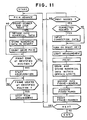
- FIG. 9 to 11 showing another embodiment of the present invention which is applied to the color printer shown in Fig. 3.
- a particular feature of this embodiment is to detect a negative film in position at a printing station by detecting front and rear edge of a picture frame of the negative film with an image sensor for measuring three color components of the transmitted light from each point of the negative image of the picture frame of the negative film placed in position at the printing station.
- the image sensor 30 is disposed to sight the center of the film framing mask 7 for detecting an edges 9a and 9b of the picture frame 2a of the negative film 2 advancing in a direction shown by an arrow in Fig. 9 as well as three color components of passed light through the picture frame 2a.
- the image sensor 30 detects the frame edges 9a and 9b at predetermined or preselected positions relative to the film framing mask 7, respectively, the negative film 2 is stopped to be placed in position in the film framing mask 7 at the printing station.
- Fig. 10 shows details of an essential part of the controller 35, for use in identifying and printing frame numbers.
- the negative film 2 is printed with the frame number bar code 3 in one side margin thereof, and the DX code 4 on the other side margin thereof.
- the frame number 5 is printed in both side margins of the film 2.
- the frame number bar code 3 is read with the bar code sensor 6. After storing temporarily the output singal from the bar code sensor 6 in a buffer memory 91, it is converted into binary numerical data with the decoder 62, the binary numerical data being stored in a memory 63.
- the image sensor 30, as is well known in the art, comprises a large number of pixels arranged in a matrix which convert incident light thereupon into electric signals and accumulate them in the form of as electric charge.
- the electric signals accumulated in the respective pixels are periodically read out to provide time-serial signals.
- the time-serial signals are converted into a digital form by an A/D converter 110 at at timing synchronized with reading out the electric charges from the image sensor 30.
- the digital signals are converted into a digital form by a logarithmic transformer 111 to provide density signals, in particular to signals representative of values proportional to densities and then sent to a comparator 112.
- unexposed portion of the negative film 2 has a base density value lower than density values of exposed frames of the negative film 2.
- an exposed frame can be detected by comparing the density value of an exposed frame with the base density value.
- a comparator 112 is provided having a threshold level representative of a density value slightly higher than the base density value to convert a density signals of each pixel of the picture frame from the logarithmic transformer 111 into a binary signal.
- Data of the binary signal is stored in a frame memory 113.
- the frame memory 113 stores data of the binary signals in synchronism with the reading out of electric charges from the image sensor 30.
- a shadowed area of the frame memory 113 is allocated to one picture frame.
- a frame identifying section 114 reads out binary signals for one line from the frame memory 113 to detect positions of the front and rear edges 9a and 9b of each picture frame and to find the center of the picture frame which lies halfway between the front and rear edges 9a and 9b. Since picture frames have indistinctive edges if exposed under artificial light, it is preferred to read out binary signals for a plurality of, for example three, lines, namely upper, middle and lower lines to find the center of a picture frame. Ar the time the center of the picture frame reaches the center position of the frame memory PL, the negative is stopped. For stopping gently the pulse motor 23, the pulse motor 23 begins to decelerate at a time the front edge 9a reaches a preselected point, for example the center position PL of the frame memory 113.
- a motor control circuit 115 under the presence of a print end signal, provides periodically drive pulses and sends them to the drive pulse number memory section 65a - 65e and the driver 51 and simultaneously a direction signal indicating a direction of rotation to driver 51.
- the driver 51 when the frame identifying section 114 provides a deceleration signal, increasingly changes the period at which the drive pulses are provided therefrom to control the pulse motor 23 to decelerate.
- a characteristic value drawing section 117 to draw characteristic values, such as large area transmittance density value, maximum and minimum density values, a density value of a specific area of the picture frame and the like, for each color.
- an exposure calculating section 118 calculates exposure for each color for controlling color filters 11 - 13.
- the image sensor 30 In advancing the negative film 2, the image sensor 30 periodically reads also the picture frame in the film framing mask 7 to provide time-serial signals which are, after having been subjected to digital and logarithmic conversions, changed into binary numerical data with the comparator 112 and stored in the frame memory 113. Since the frame memory 113 stores data in synchronism with the reading the picture frame with the image sensor 30, it stores the latest binary numerical data.
- the frame identifying section 114 reads out binary numerical data for one line from the frame memory 113 to detect the front edge 9a of the picture frame 2a.
- the frame identifying section 114 provides a deceleration signal and applied it to the motor control circuit 115.
- the motor control circuit 115 periodically provides drive pulses with a period changed longer to slow down the pulse motor 23.
- the frame identifying section 114 also detects both the front and rear edges 9a and 9b to find the center of the picture frame and, when the center of picture frame reaches the position PL, provides a stop signal and sends it to the motor control circuit 115, stopping the pulse motor 23 to thereby placing the picture frame in position at the printing station.
- a picture frame with reference also to a fixed length of advancement of the negative film 2.
- a frame identifying section 114 specifies the picture frame with reference to the length of advancement of the negative film 2 prior to the detection of the edges. In this case, when the negative film is advanced by a length as long as the pitch, the pulse motor 23 is stopped.
- a negative film strip 2 includes a plurality of, for example six, picture frames.
- Such a negative film strip 2A is usually made from a 12, 24 or 36 exposure roll of developed film for the convenience of insertion into envelope.
- the leading edge 2f of the negative film strip 2 is detected with an edge sensor 120 located at a certain distance L5 from the center of the film framing mask 7. Since the distance of each picture frame 2a - 2e from the leading edge 2f is previously known, each picture frame can be positioned by detecting an advanced length of the leading edge 2f of the negative film strip 2 after the detection of the leading edge 2f with the edge sensor 120.
- Fig. 13 shows details of an essential part of the controller 35, for use in identifying and printing frame numbers.
- the notch sensor 120 detect the notch to provide a signal which causes a counter 121 to count drive pulses from a motor control circuit 115.
- the counter 121 shifts its already counted value and restarts to count drive pulses. This means that the counter 121 can detects advanced lengths of two notches at once.
- a picture frame identifying section 122 decides whether the counter 121 has counted the number of drive pulses as many as sufficient to advance the negative film strip 2A by a distance L4 between the film framing mask 7 and the notch sensor 90. The yes decision indicates that the picture frame to be printed is placed in position in the film framing mask 7 at the printing station. Then, the identification section 122 provides a set signal.
- each picture frame 2a - 2e from the leading edge 2f is predetermined, each picture frame can be positioned by measuring the advanced distance of the leading edge of the negative film strip 2A. For example, assuming that the picture frames are arranged at regular spacings of 2 mm and the length of picture frame is 36 mm, the distance between the leading edge 2f and the center of the picture frame 2a is 20 mm (18 + 2 mm).
- the first picture frame 2a of the negative film strip 2A can be positioned by stopping the advancement of the negative film strip 2A when the counter 123 counts up drive pulses as many as corresponding to L5 + 20 mm
- the second picture frame 2b is at a distance 58 mm. (2 + 36 + 2 + 18 mm), it is positioned by stopping the advancement of the negative film strip 2A when when the counter 123 counts up drive pulses as many as corresponding to L5 + 58 mm.
- a memory 124 stores data of the numbers of drive pulses corresponding to distances of the respective picture frames 2a, 2b, .... . from the leading edge 2f, namely the distances of (L5 + 20) mm, (L4 + 58) mm, . « .
- An identifying section 125 checks the counted vale of the counter 123 with reference to the data in the memory 124 to provide a frame set signal.
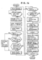
- a set signal drawing section 126 draws frame set signals from the identifying sections 114, 122 and 125 in predetermined priority order, for example in order of notch detection, frame detection and leading edge detection. If the negative film strip 2A has notches, the notch detection is prior to the other two and the set signals drawing section 126 draws a frame set signal from the identifying section 122 to provide a stop signals to the motor control circuit 115, thereby stopping the pulse motor 23 to position the picture frame. If the negative film strip 2A has no notches, the frame detection is prior to the leading edge detection and the set signals drawing section 126 draws a frame set signal from the identifying section 114 to provide a stop signals to the motor control circuit 115, thereby stopping the pulse motor 23 to position the picture frame.
- the set signals drawing section 126 draws a frame set signal from the identifying section 125 to provide a stop signals to the motor control circuit 115, thereby stopping the pulse motor 23 to position the picture frame.
- the motor control circuit 143 under the presence of a print end signal, provides a direction signal indicating a direction of rotation of the pulse motor 23 and sends it to the driver 51 simultaneously with periodic drive pulses which in turn are sent both to the driver 51, to drive pulse memories 65a - 65e and to the counters 121 and 123.
- the edge sensor 120 detects the leading edge 2f of the negative film strip 2A to provide a signal.
- the counter 123 is cuased to count drive pulses, thereby detecting an advanced length of the leading edge 2f of the negative film strip 2A. Because the negative film strip 2A shown in Fig. 12 is formed with no notches, the notch sensor 90 provides no notch signal and the counter 121 is not caused accordingly. Then, the identifying section 122 provides a signal indicating the absence of notch and sends it to the set signal drawing section 126.
- the image sensor 30 measures periodically a picture frame of the negative film strip 2A in the film framing mask 7 to provide time-serial signals which in turn are changed to binary numerical data with the comparator 112 after having been subjected to digital and logarithmic conversions and then stored in the frame memory 113. Since the frame memory 113 stores the binary numerical data in synchronism with the reading the picture frame with the image sensor 30, it stores the latest binary numerical data.
- the frame identifying section 114 provides an edge signal when detects both of the front and read edges 9a and 9b of the picture frame 2a and sends it to the set signal drawing section 126.
- the edge signal indicates that the positioning of picture frame is effective by way of frame image detection.
- the frame identifying section 114 also detects both of the front and rear edges 9a and 9b to find the center of the picture frame and, when the center of picture frame reaches the position PL, provides a set signal and sends it to the set signal drawing section 126.
- the frame identifying section 125 provides a set signal according to a position to which the leading edge 2f of the negative film strip 2A is advanced.
- the set signal drawing section 126 draws a set signal from the frame identifying section 114.
- the set signal drawing section 126 thus receiving the set signal provides a stop signal and sends it to the motor control circuit 115, stopping the pulse motor 23 to thereby placing the picture frame in position at the printing station.
- inspection of each picture frame and development of the exposed color paper are effected.
- the set signal drawing section 126 draws a set signal from the frame identification section 125 prior to the frame identification section 114. Therefore, the negative film strip 2A is positioned with reference to the distance data in the memory 124.
- the notch sensor 90 detects a notch to provide and send a notch signal to the counter 121. Consequently the counter 121 starts to count drive pulses at one counting section.
- the notch sensor 90 detects another notch, it cause the counter 121 shifts the previous count of the one counting section to the other counting section and restarts to count drive pulses at the two counting sections.
- the set signal drawing section 126 receives a signal indicating that the notch priority film positioning is possible.
- a frame set signal is provided from the frame identifying section 122 and sent to the set signal drawing section 126. Then, the set signal drawing section 126 provides and sent a stop signal to the motor control circuit 115 to stop the pulse motor 23.
- the frame identifying method of the present invention is applied to a printer in order to print frame numbers.
- the present invention can be embodied in a printer to automatically position a picture frame of a negative film or film strip to be reprinted.
- the present invention can be applied to negative film inspection apparatus. With such a negative film inspection apparatus, the exposure correction data or exposure amount data during the negative inspection process, and the identified frame number data are recorded or stored in a paper tape or a floppy disk. Such storage medium and the negative film are set in the photographic printing apparatus to print a photograph and a frame number.
Landscapes
- Physics & Mathematics (AREA)
- General Physics & Mathematics (AREA)
- Projection-Type Copiers In General (AREA)
Applications Claiming Priority (8)
| Application Number | Priority Date | Filing Date | Title |
|---|---|---|---|
| JP315708/87 | 1987-12-14 | ||
| JP62315707A JPH0820678B2 (ja) | 1987-12-14 | 1987-12-14 | 写真フイルムのコマ番号判定方法 |
| JP62315708A JPH0820679B2 (ja) | 1987-12-14 | 1987-12-14 | 写真フイルムのコマ番号判定方法 |
| JP315707/87 | 1987-12-14 | ||
| JP7292288A JPH0827483B2 (ja) | 1988-03-26 | 1988-03-26 | 写真フイルムのコマ番号判定方法 |
| JP72922/88 | 1988-03-26 | ||
| JP9746788A JPH0830851B2 (ja) | 1988-04-20 | 1988-04-20 | ピースネガのコマ番号判定方法 |
| JP97467/88 | 1988-04-20 |
Publications (3)
| Publication Number | Publication Date |
|---|---|
| EP0320880A2 true EP0320880A2 (de) | 1989-06-21 |
| EP0320880A3 EP0320880A3 (en) | 1989-12-06 |
| EP0320880B1 EP0320880B1 (de) | 1994-03-16 |
Family
ID=27465523
Family Applications (1)
| Application Number | Title | Priority Date | Filing Date |
|---|---|---|---|
| EP88120816A Expired - Lifetime EP0320880B1 (de) | 1987-12-14 | 1988-12-13 | Verfahren zur Feststellung der Bildnummern eines photographischen Filmes |
Country Status (3)
| Country | Link |
|---|---|
| US (1) | US5128519A (de) |
| EP (1) | EP0320880B1 (de) |
| DE (1) | DE3888483T2 (de) |
Cited By (4)
| Publication number | Priority date | Publication date | Assignee | Title |
|---|---|---|---|---|
| WO1991013383A1 (en) * | 1990-03-01 | 1991-09-05 | Kodak Limited | Improvements in and relating to film frame number identification |
| DE4103721A1 (de) * | 1990-02-15 | 1991-09-12 | Fuji Photo Film Co Ltd | Photo-printer |
| DE4140560A1 (de) * | 1990-12-10 | 1992-06-11 | Fuji Photo Film Co Ltd | Automatische abzugsvorrichtung und verfahren zur ueberpruefung der korrespondenz zwischen einzelbild-spezifikationsdaten und dem aktuellen einzelbild, welches in der abzugsposition in der automatischen abzugsvorrichtung angeordnet ist |
| DE4108815A1 (de) * | 1991-03-18 | 1992-09-24 | Agfa Gevaert Ag | Verfahren zur verarbeitung von entwickelten fotografischen filmen |
Families Citing this family (33)
| Publication number | Priority date | Publication date | Assignee | Title |
|---|---|---|---|---|
| US5268563A (en) * | 1988-04-28 | 1993-12-07 | Fuji Photo Film Co., Ltd. | Device for reading bar codes on photographic film |
| JPH04187768A (ja) * | 1990-11-21 | 1992-07-06 | Hitachi Ltd | 被処理物搭載用トレイの管理方法ならびに装置、および被処理物搬送装置 |
| DE59108212D1 (de) * | 1991-08-12 | 1996-10-24 | Gretag Imaging Ag | Führungsvorrichtung für Kopiervorlagen |
| EP0554639A1 (de) * | 1992-02-06 | 1993-08-11 | Gretag Imaging Ag | Verfahren zur Erstellung fotografischer Kopien von fotografischen Kopiervorlagen in einem fotografischen Kopiergerät |
| US5756981A (en) * | 1992-02-27 | 1998-05-26 | Symbol Technologies, Inc. | Optical scanner for reading and decoding one- and-two-dimensional symbologies at variable depths of field including memory efficient high speed image processing means and high accuracy image analysis means |
| US5352879A (en) * | 1992-04-30 | 1994-10-04 | Eastman Kodak Company | DX bar code reader |
| US5376806A (en) * | 1993-06-30 | 1994-12-27 | Eastman Kodak Company | Storage phosphor reader having storage phosphor size and exposure speed detection |
| JP2910534B2 (ja) * | 1993-11-18 | 1999-06-23 | ノーリツ鋼機株式会社 | 写真フィルム用コード情報読取装置 |
| US5597994A (en) * | 1993-12-06 | 1997-01-28 | Hornung; Thomas | Information display system |
| US5448049A (en) * | 1994-02-16 | 1995-09-05 | Eastman Kodak Company | Film latent image bar-code (LIBC) reader |
| US5764870A (en) * | 1994-02-28 | 1998-06-09 | Eastman Kodak Company | Method of making an index print |
| US5576794A (en) * | 1994-05-12 | 1996-11-19 | Eastman Kodak Company | Random batch photofinishing |
| JP3294437B2 (ja) * | 1994-07-13 | 2002-06-24 | 富士写真フイルム株式会社 | 写真フイルム |
| US5452055A (en) * | 1994-07-14 | 1995-09-19 | Eastman Kodak Company | Apparatus and method for making a reference exposure on a leading and/or trailing portion of a filmstrip |
| JP2845312B2 (ja) * | 1994-07-28 | 1999-01-13 | ノーリツ鋼機株式会社 | 写真感光材料用処理装置 |
| JP2979978B2 (ja) * | 1994-10-27 | 1999-11-22 | ノーリツ鋼機株式会社 | 写真焼付け装置における位置情報決定方法および写真焼付け装置 |
| JP2947090B2 (ja) * | 1994-10-27 | 1999-09-13 | ノーリツ鋼機株式会社 | ネガフィルムの搬送量の補正方法と装置 |
| US5525459A (en) * | 1995-03-15 | 1996-06-11 | Minnesota Mining And Manufacturing Company | Photographic film having a mask bar code |
| US5552855A (en) * | 1995-04-21 | 1996-09-03 | Eastman Kodak Company | Detecting apparatus for finding a reference exposure made on a leading and/or trailing portion of a filmstrip |
| US5665950A (en) * | 1995-05-30 | 1997-09-09 | Eastman Kodak Company | Fat bit bar code reader |
| JPH0980729A (ja) * | 1995-09-12 | 1997-03-28 | Fuji Photo Film Co Ltd | 写真フィルム及び写真フィルム検定方法及び装置 |
| US5933213A (en) * | 1995-09-26 | 1999-08-03 | Imation Corp. | Apparatus and method for imparting a succession of predetermined latent images on a strip of unexposed light sensitive film |
| US5969322A (en) * | 1996-07-29 | 1999-10-19 | Minolta Co., Ltd. | Apparatus having a film condition judging device |
| US6105870A (en) * | 1996-09-11 | 2000-08-22 | Fuji Photo Film Co., Ltd. | Photographic film and method of testing the photographic film and apparatus thereof |
| US5872616A (en) * | 1996-10-22 | 1999-02-16 | Eastman Kodak Company | Method of printing frame numbers from DX-coded photographic film |
| US5864126A (en) * | 1996-12-11 | 1999-01-26 | Ncr Corporation | Self reading permanent electronic label for a computing device |
| US6050489A (en) * | 1997-04-08 | 2000-04-18 | Fuji Photo Film Co., Ltd. | Bar code system for brownie film and bar code reader of camera |
| US6324345B1 (en) * | 1997-12-10 | 2001-11-27 | Fuji Photo Film Co., Ltd. | Photographic film with recorded information, method of acquiring the information recorded on photographic film, image processing method using the acquired information, and print system using the same |
| US6112982A (en) * | 1998-05-29 | 2000-09-05 | Eastman Kodak Company | Equipment for coating photographic media |
| US6206287B1 (en) | 1998-08-21 | 2001-03-27 | Eastman Kodak Company | Film optical image bar code reader |
| US7446800B2 (en) * | 2002-10-08 | 2008-11-04 | Lifetouch, Inc. | Methods for linking photographs to data related to the subjects of the photographs |
| DE102005063410A1 (de) | 2005-12-15 | 2007-10-11 | Up Management Gmbh & Co Med-Systems Kg | Blutgefäßkatheter und Injektionssystem zum Durchführen einer Blutdruckmessung eines Patienten |
| US7714908B2 (en) | 2006-05-26 | 2010-05-11 | Lifetouch Inc. | Identifying and tracking digital images with customized metadata |
Family Cites Families (12)
| Publication number | Priority date | Publication date | Assignee | Title |
|---|---|---|---|---|
| JPS52111718A (en) * | 1976-03-16 | 1977-09-19 | Fuji Photo Film Co Ltd | Printing apparatus for repeated order |
| US4207473A (en) * | 1977-06-17 | 1980-06-10 | Minolta Camera Kabushiki Kaisha | Frame detection circuitry for microfilm reader apparatus |
| JPS56128933A (en) * | 1980-03-14 | 1981-10-08 | Fuji Color Service:Kk | Display method for film frame number to print |
| DE3237053A1 (de) * | 1982-10-06 | 1984-04-12 | Agfa-Gevaert Ag, 5090 Leverkusen | Verfahren und vorrichtung zum automatischen erkennen der in einem filmstreifen liegenden bildfelder |
| CH664225A5 (de) * | 1984-07-20 | 1988-02-15 | Alos Ag | Vorrichtung zum detektieren von optischen zeichen auf einem relativ zur vorrichtung bewegten filmtraeger. |
| US4727399A (en) * | 1984-11-01 | 1988-02-23 | Fuji Photo Film Co., Ltd. | Photographic printer and method for detecting and positioning frames |
| US4659213A (en) * | 1985-04-08 | 1987-04-21 | Fuji Photo Film Co., Ltd. | Method and apparatus for detecting and processing image information |
| JPS62206534A (ja) * | 1986-03-07 | 1987-09-11 | Fuji Photo Film Co Ltd | コマ位置設定方法 |
| JP2738833B2 (ja) * | 1986-08-04 | 1998-04-08 | 富士写真フイルム株式会社 | 写真焼付方法 |
| US4806990A (en) * | 1986-10-15 | 1989-02-21 | Fuji Photo Film Co., Ltd. | Photographic printing method |
| JPH01102539A (ja) * | 1987-10-16 | 1989-04-20 | Fuji Photo Film Co Ltd | 写真フイルムのコマ番号判別方法 |
| DE3737797C2 (de) * | 1987-11-06 | 1998-03-26 | Agfa Gevaert Ag | Verfahren und Vorrichtung zur Verarbeitung von entwickelten fotografischen Filmen |
-
1988
- 1988-12-13 DE DE3888483T patent/DE3888483T2/de not_active Expired - Lifetime
- 1988-12-13 EP EP88120816A patent/EP0320880B1/de not_active Expired - Lifetime
- 1988-12-14 US US07/284,159 patent/US5128519A/en not_active Expired - Lifetime
Cited By (7)
| Publication number | Priority date | Publication date | Assignee | Title |
|---|---|---|---|---|
| DE4103721A1 (de) * | 1990-02-15 | 1991-09-12 | Fuji Photo Film Co Ltd | Photo-printer |
| WO1991013383A1 (en) * | 1990-03-01 | 1991-09-05 | Kodak Limited | Improvements in and relating to film frame number identification |
| DE4140560A1 (de) * | 1990-12-10 | 1992-06-11 | Fuji Photo Film Co Ltd | Automatische abzugsvorrichtung und verfahren zur ueberpruefung der korrespondenz zwischen einzelbild-spezifikationsdaten und dem aktuellen einzelbild, welches in der abzugsposition in der automatischen abzugsvorrichtung angeordnet ist |
| DE4140560C2 (de) * | 1990-12-10 | 1998-11-12 | Fuji Photo Film Co Ltd | Automatische Abzugsvorrichtung und Verfahren zur Überprüfung der Korrespondenz zwischen Einzelbild-Spezifikationsdaten und dem aktuellen Einzelbild, welches in der Abzugsposition in der automatischen Abzugsvorrichtung angeordnet ist |
| DE4108815A1 (de) * | 1991-03-18 | 1992-09-24 | Agfa Gevaert Ag | Verfahren zur verarbeitung von entwickelten fotografischen filmen |
| US5253011A (en) * | 1991-03-18 | 1993-10-12 | Agfa-Gevaert Aktiengesellschaft | Copying method and copier for film |
| DE4108815C2 (de) * | 1991-03-18 | 2000-05-25 | Agfa Gevaert Ag | Verfahren zur Verarbeitung von entwickelten fotografischen Filmen |
Also Published As
| Publication number | Publication date |
|---|---|
| EP0320880A3 (en) | 1989-12-06 |
| US5128519A (en) | 1992-07-07 |
| EP0320880B1 (de) | 1994-03-16 |
| DE3888483T2 (de) | 1994-06-23 |
| DE3888483D1 (de) | 1994-04-21 |
Similar Documents
| Publication | Publication Date | Title |
|---|---|---|
| EP0320880B1 (de) | Verfahren zur Feststellung der Bildnummern eines photographischen Filmes | |
| US4918484A (en) | Picture frame number discriminating method and apparatus therefor | |
| CN100430821C (zh) | 摄影和视频图像系统 | |
| EP0331049B1 (de) | Vorrichtung zum Lesen des Strichcodes eines photographischen Filmes | |
| US4933713A (en) | Photographic printing method and apparatus therefor | |
| US5978067A (en) | Photographic camera system | |
| EP0561592B1 (de) | Photographischer Filmprinter | |
| US5336873A (en) | Photographic film having frame number bar codes | |
| RU1836650C (ru) | Полоса фотопленки и копировальное устройство | |
| JP2568346B2 (ja) | 感光性材料を処理する装置 | |
| EP0423810B1 (de) | Photographisches Reproduktionsverfahren und photographischer Reproduktionsapparat | |
| US4806990A (en) | Photographic printing method | |
| US5179266A (en) | Photographic film and method of identifying frame numbers of photographic film | |
| US4728996A (en) | Photographic printing method | |
| US5157437A (en) | Apparatus and method for checking coincidence between frame specification data and an actual frame of an auto-printer | |
| EP0364991B1 (de) | Verfahren und Vorrichtung zur Herstellung von Photos | |
| JP2578494B2 (ja) | 写真フィルム及びそのフレームナンバー続取方法 | |
| JPH01245234A (ja) | 写真フイルムのコマ番号判定方法 | |
| JPH0820678B2 (ja) | 写真フイルムのコマ番号判定方法 | |
| US6600880B2 (en) | Photographic camera system | |
| JPH0830851B2 (ja) | ピースネガのコマ番号判定方法 | |
| US5406350A (en) | Image recording apparatus | |
| JPH01155330A (ja) | 写真フイルムのコマ番号判定方法 | |
| JPH04213447A (ja) | オートプリンタのコマ番号印字方法 | |
| JPH0666026B2 (ja) | ネガフィルムの装着異常検出方法 |
Legal Events
| Date | Code | Title | Description |
|---|---|---|---|
| PUAI | Public reference made under article 153(3) epc to a published international application that has entered the european phase |
Free format text: ORIGINAL CODE: 0009012 |
|
| AK | Designated contracting states |
Kind code of ref document: A2 Designated state(s): DE FR GB |
|
| PUAL | Search report despatched |
Free format text: ORIGINAL CODE: 0009013 |
|
| AK | Designated contracting states |
Kind code of ref document: A3 Designated state(s): DE FR GB |
|
| 17P | Request for examination filed |
Effective date: 19900312 |
|
| 17Q | First examination report despatched |
Effective date: 19920323 |
|
| GRAA | (expected) grant |
Free format text: ORIGINAL CODE: 0009210 |
|
| AK | Designated contracting states |
Kind code of ref document: B1 Designated state(s): DE FR GB |
|
| REF | Corresponds to: |
Ref document number: 3888483 Country of ref document: DE Date of ref document: 19940421 |
|
| ET | Fr: translation filed | ||
| PLBE | No opposition filed within time limit |
Free format text: ORIGINAL CODE: 0009261 |
|
| STAA | Information on the status of an ep patent application or granted ep patent |
Free format text: STATUS: NO OPPOSITION FILED WITHIN TIME LIMIT |
|
| 26N | No opposition filed | ||
| REG | Reference to a national code |
Ref country code: GB Ref legal event code: IF02 |
|
| REG | Reference to a national code |
Ref country code: GB Ref legal event code: 732E |
|
| REG | Reference to a national code |
Ref country code: FR Ref legal event code: CD Ref country code: FR Ref legal event code: TP |
|
| PGFP | Annual fee paid to national office [announced via postgrant information from national office to epo] |
Ref country code: GB Payment date: 20071219 Year of fee payment: 20 |
|
| PGFP | Annual fee paid to national office [announced via postgrant information from national office to epo] |
Ref country code: DE Payment date: 20080130 Year of fee payment: 20 |
|
| PGFP | Annual fee paid to national office [announced via postgrant information from national office to epo] |
Ref country code: FR Payment date: 20071214 Year of fee payment: 20 |
|
| REG | Reference to a national code |
Ref country code: GB Ref legal event code: PE20 Expiry date: 20081212 |
|
| PG25 | Lapsed in a contracting state [announced via postgrant information from national office to epo] |
Ref country code: GB Free format text: LAPSE BECAUSE OF EXPIRATION OF PROTECTION Effective date: 20081212 |