EP0320885A2 - Füllung für Destillierkolonnen zur kryogenen Scheidung von Luft - Google Patents
Füllung für Destillierkolonnen zur kryogenen Scheidung von Luft Download PDFInfo
- Publication number
- EP0320885A2 EP0320885A2 EP88120824A EP88120824A EP0320885A2 EP 0320885 A2 EP0320885 A2 EP 0320885A2 EP 88120824 A EP88120824 A EP 88120824A EP 88120824 A EP88120824 A EP 88120824A EP 0320885 A2 EP0320885 A2 EP 0320885A2
- Authority
- EP
- European Patent Office
- Prior art keywords
- less
- oxygen
- packing
- liquid
- vapor
- Prior art date
- Legal status (The legal status is an assumption and is not a legal conclusion. Google has not performed a legal analysis and makes no representation as to the accuracy of the status listed.)
- Withdrawn
Links
Images


Classifications
-
- F—MECHANICAL ENGINEERING; LIGHTING; HEATING; WEAPONS; BLASTING
- F25—REFRIGERATION OR COOLING; COMBINED HEATING AND REFRIGERATION SYSTEMS; HEAT PUMP SYSTEMS; MANUFACTURE OR STORAGE OF ICE; LIQUEFACTION SOLIDIFICATION OF GASES
- F25J—LIQUEFACTION, SOLIDIFICATION OR SEPARATION OF GASES OR GASEOUS OR LIQUEFIED GASEOUS MIXTURES BY PRESSURE AND COLD TREATMENT OR BY BRINGING THEM INTO THE SUPERCRITICAL STATE
- F25J3/00—Processes or apparatus for separating the constituents of gaseous or liquefied gaseous mixtures involving the use of liquefaction or solidification
- F25J3/02—Processes or apparatus for separating the constituents of gaseous or liquefied gaseous mixtures involving the use of liquefaction or solidification by rectification, i.e. by continuous interchange of heat and material between a vapour stream and a liquid stream
- F25J3/04—Processes or apparatus for separating the constituents of gaseous or liquefied gaseous mixtures involving the use of liquefaction or solidification by rectification, i.e. by continuous interchange of heat and material between a vapour stream and a liquid stream for air
- F25J3/04763—Start-up or control of the process; Details of the apparatus used
- F25J3/04866—Construction and layout of air fractionation equipments, e.g. valves, machines
- F25J3/04896—Details of columns, e.g. internals, inlet/outlet devices
-
- B—PERFORMING OPERATIONS; TRANSPORTING
- B01—PHYSICAL OR CHEMICAL PROCESSES OR APPARATUS IN GENERAL
- B01D—SEPARATION
- B01D3/00—Distillation or related exchange processes in which liquids are contacted with gaseous media, e.g. stripping
- B01D3/14—Fractional distillation or use of a fractionation or rectification column
- B01D3/32—Other features of fractionating columns ; Constructional details of fractionating columns not provided for in groups B01D3/16 - B01D3/30
-
- B—PERFORMING OPERATIONS; TRANSPORTING
- B01—PHYSICAL OR CHEMICAL PROCESSES OR APPARATUS IN GENERAL
- B01J—CHEMICAL OR PHYSICAL PROCESSES, e.g. CATALYSIS OR COLLOID CHEMISTRY; THEIR RELEVANT APPARATUS
- B01J19/00—Chemical, physical or physico-chemical processes in general; Their relevant apparatus
- B01J19/30—Loose or shaped packing elements, e.g. Raschig rings or Berl saddles, for pouring into the apparatus for mass or heat transfer
-
- F—MECHANICAL ENGINEERING; LIGHTING; HEATING; WEAPONS; BLASTING
- F25—REFRIGERATION OR COOLING; COMBINED HEATING AND REFRIGERATION SYSTEMS; HEAT PUMP SYSTEMS; MANUFACTURE OR STORAGE OF ICE; LIQUEFACTION SOLIDIFICATION OF GASES
- F25J—LIQUEFACTION, SOLIDIFICATION OR SEPARATION OF GASES OR GASEOUS OR LIQUEFIED GASEOUS MIXTURES BY PRESSURE AND COLD TREATMENT OR BY BRINGING THEM INTO THE SUPERCRITICAL STATE
- F25J3/00—Processes or apparatus for separating the constituents of gaseous or liquefied gaseous mixtures involving the use of liquefaction or solidification
- F25J3/02—Processes or apparatus for separating the constituents of gaseous or liquefied gaseous mixtures involving the use of liquefaction or solidification by rectification, i.e. by continuous interchange of heat and material between a vapour stream and a liquid stream
- F25J3/04—Processes or apparatus for separating the constituents of gaseous or liquefied gaseous mixtures involving the use of liquefaction or solidification by rectification, i.e. by continuous interchange of heat and material between a vapour stream and a liquid stream for air
- F25J3/04763—Start-up or control of the process; Details of the apparatus used
- F25J3/04769—Operation, control and regulation of the process; Instrumentation within the process
- F25J3/04854—Safety aspects of operation
-
- F—MECHANICAL ENGINEERING; LIGHTING; HEATING; WEAPONS; BLASTING
- F25—REFRIGERATION OR COOLING; COMBINED HEATING AND REFRIGERATION SYSTEMS; HEAT PUMP SYSTEMS; MANUFACTURE OR STORAGE OF ICE; LIQUEFACTION SOLIDIFICATION OF GASES
- F25J—LIQUEFACTION, SOLIDIFICATION OR SEPARATION OF GASES OR GASEOUS OR LIQUEFIED GASEOUS MIXTURES BY PRESSURE AND COLD TREATMENT OR BY BRINGING THEM INTO THE SUPERCRITICAL STATE
- F25J3/00—Processes or apparatus for separating the constituents of gaseous or liquefied gaseous mixtures involving the use of liquefaction or solidification
- F25J3/02—Processes or apparatus for separating the constituents of gaseous or liquefied gaseous mixtures involving the use of liquefaction or solidification by rectification, i.e. by continuous interchange of heat and material between a vapour stream and a liquid stream
- F25J3/04—Processes or apparatus for separating the constituents of gaseous or liquefied gaseous mixtures involving the use of liquefaction or solidification by rectification, i.e. by continuous interchange of heat and material between a vapour stream and a liquid stream for air
- F25J3/04763—Start-up or control of the process; Details of the apparatus used
- F25J3/04866—Construction and layout of air fractionation equipments, e.g. valves, machines
- F25J3/04896—Details of columns, e.g. internals, inlet/outlet devices
- F25J3/04909—Structured packings
-
- B—PERFORMING OPERATIONS; TRANSPORTING
- B01—PHYSICAL OR CHEMICAL PROCESSES OR APPARATUS IN GENERAL
- B01J—CHEMICAL OR PHYSICAL PROCESSES, e.g. CATALYSIS OR COLLOID CHEMISTRY; THEIR RELEVANT APPARATUS
- B01J2219/00—Chemical, physical or physico-chemical processes in general; Their relevant apparatus
- B01J2219/30—Details relating to random packing elements
- B01J2219/304—Composition or microstructure of the elements
- B01J2219/30408—Metal
-
- F—MECHANICAL ENGINEERING; LIGHTING; HEATING; WEAPONS; BLASTING
- F25—REFRIGERATION OR COOLING; COMBINED HEATING AND REFRIGERATION SYSTEMS; HEAT PUMP SYSTEMS; MANUFACTURE OR STORAGE OF ICE; LIQUEFACTION SOLIDIFICATION OF GASES
- F25J—LIQUEFACTION, SOLIDIFICATION OR SEPARATION OF GASES OR GASEOUS OR LIQUEFIED GASEOUS MIXTURES BY PRESSURE AND COLD TREATMENT OR BY BRINGING THEM INTO THE SUPERCRITICAL STATE
- F25J2290/00—Other details not covered by groups F25J2200/00 - F25J2280/00
- F25J2290/10—Mathematical formulae, modeling, plot or curves; Design methods
-
- F—MECHANICAL ENGINEERING; LIGHTING; HEATING; WEAPONS; BLASTING
- F25—REFRIGERATION OR COOLING; COMBINED HEATING AND REFRIGERATION SYSTEMS; HEAT PUMP SYSTEMS; MANUFACTURE OR STORAGE OF ICE; LIQUEFACTION SOLIDIFICATION OF GASES
- F25J—LIQUEFACTION, SOLIDIFICATION OR SEPARATION OF GASES OR GASEOUS OR LIQUEFIED GASEOUS MIXTURES BY PRESSURE AND COLD TREATMENT OR BY BRINGING THEM INTO THE SUPERCRITICAL STATE
- F25J2290/00—Other details not covered by groups F25J2200/00 - F25J2280/00
- F25J2290/44—Particular materials used, e.g. copper, steel or alloys thereof or surface treatments used, e.g. enhanced surface
Definitions
- This invention relates generally to a cryogenic process for the separation of an oxygen containing mixture to produce an enriched product by means of passing streams of liquid and vapor countercurrently through a mass transfer zone containing packing elements fabricated from thin material in order to effect vapor-liquid contact.
- the packing utilized is a copper-containing material having certain specified properties and characteristics.
- Mass transfer and distillation columns of various types have been known in the art for many years.
- enhanced vapor-liquid contact in columns of this type has been effected through the use, for example, of perforated or sieve trays whereby the rising vapor passes through openings, or through bubble caps, in trays on which a pool of the liquid is maintained at a significant depth.
- the vapor-liquid contact is controlled and enhanced.
- vapor-liquid contact can also be achieved through the utilization of packing elements in lieu of bubbling the vapor through pools of liquid on trays.
- Packing elements such as saddles and Raschig rings are well known in the art for such employment.
- materials of fabrication for the trays and packing materials have been suggested. Illustrative of these are carbon steel, stainless steel, aluminum alloys, copper alloys, and plastics of various types.
- these trays usually contain a liquid inventory equivalent to a depth of 30 to 50 or more millimeters.
- the thickness of the tray alone militates against the propagation of combustion of the material, even in the presence of a relatively high concentration of oxygen, and the presence of the liquid inventory on the tray would act to quench the combustion reaction.
- the material used to fabricate packing elements is relatively thin and thus more susceptible to combustion.
- the liquid being contacted with the vapor is in the form of a thin film on the surface of the elements, which film is several orders of magnitude thinner than the height of the liquid inventory on a tray.
- cryogenic separation of oxygen-containing mixtures can be safely practiced when certain defined materials are utilized as packing elements in the mass transfer or vapor-liquid contact zones.
- These packing elements can be random-type packings (such as saddles, Raschig rings and Pall rings) and can be ordered or structured-type packings.
- structured or ordered packing is meant a packing which will promote liquid and vapor mixing in a direction perpendicular to the primary flow direction.
- the packing elements are fabricated from a copper containing material which has a copper concentration of at least about 30% by weight.
- the material from which the packing elements are fabricated is to have a heat of reaction with oxygen at 20°C of less than about 1.0 Kcal/g.
- the packing element is fabricated from a material containing at least about 50% by weight copper and especially materials containing even higher concentrations of copper such as for example 55, 60, 65 and even 70, by weight copper.
- Particularly suitable materials have been found to be alloys containing from about 60 or 63% up to about 70% copper, e.g. brass.
- the process of our invention can also be practiced utilizing packing materials having extremely high copper contents such as 85, 90 or higher.
- Commercial grades of copper containing 99%+ copper content are also quite suitable. Materials of the type described above are readily available commercially today and include various materials such as Monel, nickel silver, naval brass, cartridge brass, red brass, commercial brass, phosphor bronze and various commercial grades of copper.
- the process of our invention is advantageously practiced when employing packing elements fabricated from materials having a thickness of less than about 1/2 millimeter and particularly less than about 0.30 millimeter.
- the process of our invention is especially advantageous in the employment of packing elements fabricated from materials having a thickness of less than about 0.20 millimeter.
- the material from which the packing elements are to be fabricated can have a heat of reaction with oxygen at 20°C. of less than about 0.95 Kcal/g and even less than 0.85 Kcal/g. It is particularly desirable to employ materials having a heat of reaction of less than about 0.80 Kcal/g.
- the process of this invention becomes more advantageous as the oxygen concentration in the vapor phase increases.
- the process of this invention is generally advantageous when the oxygen concentration is greater than that normally found in atmospheric air, greater than about 21% by volume, the process becomes more advantageous when the oxygen concentration in the vapor phase is greater than about 50% by volume.
- the process of our invention is particularly advantageous when the oxygen concentration in the vapor phase is greater than about 70% by volume and especially so when the concentration exceeds about 80 or even 95% by volume.
- cryogenic air separation processes are conducted at about atmospheric pressure, or just slightly above, and the advantages of the present process are obtainable at these relatively low pressures.
- Distillation can be practiced at pressures less than the critical pressure of the system.
- distillation can be effected at less than about 475 psig.
- From a process point of view it can be advantageous to utilize pressures of less than about 200 psig and particularly less than about 125 psig.
- the process of this invention can provide especially advantageous operation when employing pressures in the range of less than about 50 psig and particularly less than about 25 psig.
- the liquid film on the surface of the packing elements is generally less than about 1 millimeter.
- the advantages of this invention are usually more readily manifest when the thickness of the liquid film on the packing elements is less than about 1/2 millimeter, particularly when it is less than about 0.25 millimeter, and especially when it is less than about 0.1 millimeter. At times the liquid film can be as thin as 0.05 or even 0.025 millimeter.
- such materials generally have a specific area of at least about 300 square meters per cubic meter of packing elements.
- the specific area of the packing material is at least about 400 square meters per cubic meter and it is particularly preferred to utilize a material having a specific area of at least about 500 square meters per cubic meter and especially greater than about 600 square meters per cubic meter.
- the packing elements are fabricated so as to have a bulk density of less than about 1,000 kilograms per cubic meter, preferably less than about 700 kilograms per cubic meter, and especially less than about 400 kilograms per cubic meter.
- the interrelationship between the specific area and the bulk density of the packing material is determinative of the thickness of the material to be employed.
- a mass transfer column 10 utilized for cryogenic air separation.
- Pretreated dry oxygen-containing gas is introduced into column 10 by means of line 12.
- a pressure maintained at less than about 150 psig, and preferably less than about 50 or even 25 psig, is maintained, liquid and vapor are contacted with each other in a countercurrent fashion with the vapor rising within column 10 and being removed therefrom by means of line 14 as a nitrogen enriched stream.
- a portion of the vapor from line 14 is passed by means of line 16 to cooler 18 where it is condensed to form reflux liquid which is returned to column 10 by means of line 20.
- the liquid flows downwardly within column 10 countercurrent to the upwardly flowing vapor and the oxygen enriched liquid is removed from column 10 by means of line 22.
- a portion of the liquid in line 22 is passed, via line 24, to reboiler 26. There it is heated and vaporized and the vapor is returned to the column 10 by means of line 28. This vapor flows upwardly within column 10 countercurrently to the liquid.
- packing material 30 having a specific area of greater than about 350 square meters per cubic meter and a bulk density of less than about 375 kilograms per cubic meter. As illustrated in Figure 1, the packing material provides means for the liquid to flow downwardly in the form of thin films of less than about about 0.15 millimeter on the surface of the packing material, while permitting the vapor to flow upwardly between the packing elements resulting in contact between the countercurrently flowing liquid and vapor.
- the material of fabrication of the packing elements utilized is as described in this invention.
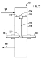
- test specimens of various materials were subjected to testing in an apparatus which will be described in connection with FIG. 2.
- the test apparatus 100 generally consisted of a vertical test vessel 110 of 41 mm inside diameter.
- the test specimens 112 were mounted coaxially within the vessel 110 by being held by mounting block 114, which in turn was supported by mounting brackets 116 affixed to the interior of test vessel 110.
- the lower end of the test specimen 112 was located 50 mm above the midpoint of test vessel 110 between a pair of electrodes 118 used for ignition. Molten slag and burning metal were collected in the bottom of test vessel 110.
- Two separate test vessels 110 were used in the following Examples. One was a brass vessel rated for pressures up to 2.2 MPa (315 psi). The other was stainless steel vessel with a brass liner having the same internal dimensions but rated for 10.4 MPa (1515 psi).
- a gas supply system including an O2 analyzer to measure the composition of blended feed gas mixtures and a chromatograph to analyze premixed gases, provided metered flows of feed gas comprised O2 and diluent to the top of the test vessel 110 by means of gas inlet line 120. This feed gas was supplied at a temperature of 25°C. Gas was removed from test vessel 110 at a point below the lower end of test specimen 112 by means of gas outlet line 122 and passed to a back-pressure regulator (not shown) used to control the pressure in test vessel 110.
- test specimens 112 were 2-3/4 to 3 in. long.
- a promoter or igniter 124 was attached to the bottom 4.8 mm of the test specimen 112.
- the two opposing electrodes 118 were pressed against the igniter 124 by pneumatic cylinders (not shown) and a direct current was passed through it for about one second. In this manner the test specimens 112 were ignited at the bottom so that combustion propagated upwards. This configuration permitted the molten slag and burning metal to fall away from the test specimen 112, giving more accurate and reproducible results.
- the igniter or promoter 124 was applied to the bottom of a test specimen 112 to be tested and the test specimen 112 was mounted in mounting block 114 within the test vessel 110.
- Test vessel 110 was closed and the inlet gas flow through line 120 was started. The gas component flow rates and the pressure were adjusted to the desired values. The system was purged until the effluent gas composition from line 122 and the total gas flow were constant at the desired values.
- the total gas flow was set to 0.33 standard litre/s, giving gas velocities of 250 mm/s (0.8 ft/s) at 100 kPa (14.7 psi) to 12 mm/s (0.04 ft/sec) at 10.4 MPa (1515 psi). Reynolds numbers were in the range of 640 to 670, based on the 41 mm inside diameter of the vessel. When all conditions were set, the electrodes 118 activated and the test commenced.
- test specimen 112 was removed for examination and the remaining, unconsumed portion (if any) of the test specimen 112 was measured and the length thereof recorded.
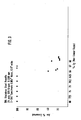
- a series of 304 stainless steel test specimens having a heat of combustion with oxygen at 20° C. of 1.9 Kcal/g were subjected to flammability testing employing a mixture of gaseous oxygen and argon at a pressure of 25 psig.
- the test specimens were 2-3/4 inches long by 0.5 inch wide and 0.004 inch (0.1016 mm) thick.
- the igniters employed for the tests utilizing oxygen concentrations in the range from 67 to 80% by volume were 4 wraps of 5 mil steel and the igniter employed for the tests utilizing 66% by volume oxygen were 2 mil steel with steel wool or magnesium.
- the tests of this example were conducted in the manner described above and the measurements of the test specimens are plotted in FIG. 3.
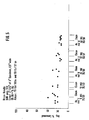
- a series of 3003 aluminum test specimens having a heat of combustion with oxygen at 20° C. of about 7.4 Kcal/g were subjected to flammability testing employing a mixture of gaseous oxygen and argon at a pressure of 25 psig.
- the test specimens were 2-3/4 inches long by 0.5 inch wide and 0.008 inch (0.2032 mm) thick.
- the igniters employed for the tests utilizing oxygen concentrations of 78% by volume and greater were 1 wrap of 5 mil steel, the igniters employed for the tests utilizing from 74 to 78% by volume oxygen were 5 mil steel with added magnesium wire, and the igniters employed for the tests utilizing from 72% by volume oxygen and less were 2 mil steel with added magnesium wire.
- the tests of this Example were conducted in the manner described above and the measurements of the test specimens are plotted in FIG. 4.
- test specimens having different copper contents were subjected to flammability testing employing substantially pure gaseous oxygen (99.99% by vol.) at a pressure of 1500 psig.
- the test specimens were 3 inches long by 0.5 inch wide and ranged from 0.005 inch (0.1270 mm) to 0.04 inch (1.016 mm) thick.
- the test specimens having a copper content of 70% by weight had a heat of reaction with oxygen at 20° C. of 0.79 Kcal/g, while the test specimens having a copper content of 63% by weight had a heat of reaction with oxygen of 0.84 Kcal/g.
- the igniters employed for all of the tests were 4 wraps of 5 mil carbon steel. The tests of this example were conducted in the manner described above and the measurements of the test specimens are plotted in FIG. 5.
Landscapes
- Engineering & Computer Science (AREA)
- Physics & Mathematics (AREA)
- Thermal Sciences (AREA)
- Chemical & Material Sciences (AREA)
- Mechanical Engineering (AREA)
- General Engineering & Computer Science (AREA)
- Chemical Kinetics & Catalysis (AREA)
- Organic Chemistry (AREA)
- Separation By Low-Temperature Treatments (AREA)
- Vaporization, Distillation, Condensation, Sublimation, And Cold Traps (AREA)
- Physical Or Chemical Processes And Apparatus (AREA)
- Separation Using Semi-Permeable Membranes (AREA)
Applications Claiming Priority (2)
| Application Number | Priority Date | Filing Date | Title |
|---|---|---|---|
| US13251587A | 1987-12-14 | 1987-12-14 | |
| US132515 | 1987-12-14 |
Publications (2)
| Publication Number | Publication Date |
|---|---|
| EP0320885A2 true EP0320885A2 (de) | 1989-06-21 |
| EP0320885A3 EP0320885A3 (de) | 1989-08-23 |
Family
ID=22454397
Family Applications (1)
| Application Number | Title | Priority Date | Filing Date |
|---|---|---|---|
| EP88120824A Withdrawn EP0320885A3 (de) | 1987-12-14 | 1988-12-13 | Füllung für Destillierkolonnen zur kryogenen Scheidung von Luft |
Country Status (9)
| Country | Link |
|---|---|
| EP (1) | EP0320885A3 (de) |
| JP (1) | JPH024189A (de) |
| KR (1) | KR910002168B1 (de) |
| AU (1) | AU2663188A (de) |
| CA (1) | CA1280968C (de) |
| DE (1) | DE320885T1 (de) |
| DK (1) | DK693888A (de) |
| FI (1) | FI885760A7 (de) |
| NO (1) | NO885526L (de) |
Cited By (1)
| Publication number | Priority date | Publication date | Assignee | Title |
|---|---|---|---|---|
| EP4192615A4 (de) * | 2020-08-06 | 2024-05-15 | Air Company Holdings, Inc. | Legierungen und verfahren zur verbesserten entfernung von verunreinigungen in destillationsverfahren |
Families Citing this family (3)
| Publication number | Priority date | Publication date | Assignee | Title |
|---|---|---|---|---|
| JP2686039B2 (ja) * | 1993-11-12 | 1997-12-08 | 大同ほくさん株式会社 | 酸素ガス製造装置 |
| JP4717777B2 (ja) * | 2006-10-25 | 2011-07-06 | 三機工業株式会社 | 気液接触用充填要素、気液接触用充填材および気液接触用充填要素の製造方法 |
| CN104307459A (zh) * | 2014-10-02 | 2015-01-28 | 北京玉珠峰科技有限公司 | 一种新型气液交换填料 |
Family Cites Families (3)
| Publication number | Priority date | Publication date | Assignee | Title |
|---|---|---|---|---|
| FR596747A (fr) * | 1924-07-17 | 1925-10-30 | Julien Wurth Et Cie | Perfectionnements apportés aux spirales de remplissage pour colonnes de réaction et de contact |
| DE1751501B2 (de) * | 1968-06-10 | 1972-06-15 | Linde Ag, 6200 Wiesbaden | Fuellmasse fuer tieftemperatur-regeneratoren |
| EP0070915A1 (de) * | 1981-07-30 | 1983-02-09 | GebràDer Sulzer Aktiengesellschaft | Einbauelement für eine Vorrichtung für Stoff- und direkten Wärmeaustausch und Mischen |
-
1988
- 1988-12-07 AU AU26631/88A patent/AU2663188A/en not_active Abandoned
- 1988-12-08 CA CA000585330A patent/CA1280968C/en not_active Expired - Lifetime
- 1988-12-13 DE DE198888120824T patent/DE320885T1/de active Pending
- 1988-12-13 NO NO88885526A patent/NO885526L/no unknown
- 1988-12-13 DK DK693888A patent/DK693888A/da not_active Application Discontinuation
- 1988-12-13 FI FI885760A patent/FI885760A7/fi not_active Application Discontinuation
- 1988-12-13 EP EP88120824A patent/EP0320885A3/de not_active Withdrawn
- 1988-12-14 JP JP63316059A patent/JPH024189A/ja active Granted
- 1988-12-14 KR KR1019880016620A patent/KR910002168B1/ko not_active Expired
Cited By (1)
| Publication number | Priority date | Publication date | Assignee | Title |
|---|---|---|---|---|
| EP4192615A4 (de) * | 2020-08-06 | 2024-05-15 | Air Company Holdings, Inc. | Legierungen und verfahren zur verbesserten entfernung von verunreinigungen in destillationsverfahren |
Also Published As
| Publication number | Publication date |
|---|---|
| DE320885T1 (de) | 1989-10-26 |
| DK693888A (da) | 1989-06-15 |
| JPH024189A (ja) | 1990-01-09 |
| EP0320885A3 (de) | 1989-08-23 |
| NO885526L (no) | 1989-06-15 |
| FI885760L (fi) | 1989-06-15 |
| AU2663188A (en) | 1989-06-15 |
| DK693888D0 (da) | 1988-12-13 |
| FI885760A0 (fi) | 1988-12-13 |
| NO885526D0 (no) | 1988-12-13 |
| JPH0526112B2 (de) | 1993-04-15 |
| CA1280968C (en) | 1991-03-05 |
| KR910002168B1 (ko) | 1991-04-06 |
| FI885760A7 (fi) | 1989-06-15 |
| KR890009454A (ko) | 1989-08-02 |
Similar Documents
| Publication | Publication Date | Title |
|---|---|---|
| KR100454610B1 (ko) | 합성가스의제조방법 | |
| Lin et al. | An integrated purification and production of hydrogen with a palladium membrane-catalytic reactor | |
| DK174008B1 (da) | Gasblander og -fordeler til reaktor | |
| US4789384A (en) | Process for partial oxidation of a hydrocarbon-containing fuel | |
| US4813988A (en) | Suitable distillation column packing for the cryogenic separation of air | |
| US2257293A (en) | Manufacture of hydrocarbons | |
| US2419565A (en) | Carbon black process and apparatus | |
| EP0320885A2 (de) | Füllung für Destillierkolonnen zur kryogenen Scheidung von Luft | |
| Peramanu et al. | Solubility study for the purification of hydrogen from high pressure hydrocracker off‐gas by an absorption‐stripping process | |
| US3969490A (en) | Production of hydrogen chloride by thermal dissociation of organic substances containing chlorine | |
| US4590318A (en) | Method for producing vinyl chloride | |
| EP0866141A1 (de) | Verfahren zum Herstellen von sauerstofffreie Schutzgasen mit niedriger Taupunkt zur Verwendung in Wärmebehandlungen | |
| US5049508A (en) | Apparatus and process for total sulfur determination | |
| US4042640A (en) | Oxychlorination of hydrocarbons | |
| GB1443277A (en) | Process for producing methane-rich gases from hydrocarbons | |
| Pan | Characteristics of Pt-Rh gauze catalyst and kinetics of the HCN synthesis | |
| UA52630C2 (uk) | Спосіб дистиляції етиленоксиду | |
| CA2428339C (en) | Process for producing synthesis gas by non-catalytic partial oxidation of natural gas | |
| US4216194A (en) | Method of producing methane and carbon | |
| CA2088973C (en) | Process for the purification of acetic anhydride and acetic acid | |
| US3452114A (en) | Production of acetylene by incomplete combustion of hydrocarbons with oxygen | |
| US4071571A (en) | Control of molten salt oxidation in production of chlorinated hydrocarbons | |
| US3063803A (en) | Turbulent flow flame synthesis of hydrogen cyanide | |
| US3576606A (en) | Reactor for the manufacture of nitric oxide | |
| US4491572A (en) | Process for preparing sulfur dioxide |
Legal Events
| Date | Code | Title | Description |
|---|---|---|---|
| PUAI | Public reference made under article 153(3) epc to a published international application that has entered the european phase |
Free format text: ORIGINAL CODE: 0009012 |
|
| AK | Designated contracting states |
Kind code of ref document: A2 Designated state(s): BE DE ES FR GB GR IT NL SE |
|
| PUAL | Search report despatched |
Free format text: ORIGINAL CODE: 0009013 |
|
| RHK1 | Main classification (correction) |
Ipc: F25J 3/04 |
|
| AK | Designated contracting states |
Kind code of ref document: A3 Designated state(s): BE DE ES FR GB GR IT NL SE |
|
| TCNL | Nl: translation of patent claims filed | ||
| DET | De: translation of patent claims | ||
| EL | Fr: translation of claims filed | ||
| 17P | Request for examination filed |
Effective date: 19891030 |
|
| 17Q | First examination report despatched |
Effective date: 19900709 |
|
| STAA | Information on the status of an ep patent application or granted ep patent |
Free format text: STATUS: THE APPLICATION HAS BEEN WITHDRAWN |
|
| 18W | Application withdrawn |
Withdrawal date: 19910821 |