EP0320892A1 - Rasoir à tête pivotante - Google Patents
Rasoir à tête pivotante Download PDFInfo
- Publication number
- EP0320892A1 EP0320892A1 EP88120849A EP88120849A EP0320892A1 EP 0320892 A1 EP0320892 A1 EP 0320892A1 EP 88120849 A EP88120849 A EP 88120849A EP 88120849 A EP88120849 A EP 88120849A EP 0320892 A1 EP0320892 A1 EP 0320892A1
- Authority
- EP
- European Patent Office
- Prior art keywords
- head
- razor
- razor blade
- oscillating
- locking device
- Prior art date
- Legal status (The legal status is an assumption and is not a legal conclusion. Google has not performed a legal analysis and makes no representation as to the accuracy of the status listed.)
- Granted
Links
- 230000007935 neutral effect Effects 0.000 abstract 1
- 230000006835 compression Effects 0.000 description 5
- 238000007906 compression Methods 0.000 description 5
- 238000006073 displacement reaction Methods 0.000 description 4
- 239000000969 carrier Substances 0.000 description 1
- 238000010276 construction Methods 0.000 description 1
- 230000002349 favourable effect Effects 0.000 description 1
Images


Classifications
-
- B—PERFORMING OPERATIONS; TRANSPORTING
- B26—HAND CUTTING TOOLS; CUTTING; SEVERING
- B26B—HAND-HELD CUTTING TOOLS NOT OTHERWISE PROVIDED FOR
- B26B21/00—Razors of the open or knife type; Safety razors or other shaving implements of the planing type; Hair-trimming devices involving a razor-blade; Equipment therefor
- B26B21/40—Details or accessories
- B26B21/52—Handles, e.g. tiltable, flexible
- B26B21/521—Connection details, e.g. connection to razor heads
-
- B—PERFORMING OPERATIONS; TRANSPORTING
- B26—HAND CUTTING TOOLS; CUTTING; SEVERING
- B26B—HAND-HELD CUTTING TOOLS NOT OTHERWISE PROVIDED FOR
- B26B21/00—Razors of the open or knife type; Safety razors or other shaving implements of the planing type; Hair-trimming devices involving a razor-blade; Equipment therefor
- B26B21/08—Razors of the open or knife type; Safety razors or other shaving implements of the planing type; Hair-trimming devices involving a razor-blade; Equipment therefor involving changeable blades
- B26B21/14—Safety razors with one or more blades arranged transversely to the handle
- B26B21/22—Safety razors with one or more blades arranged transversely to the handle involving several blades to be used simultaneously
- B26B21/222—Safety razors with one or more blades arranged transversely to the handle involving several blades to be used simultaneously with the blades moulded into, or attached to, a changeable unit
- B26B21/225—Safety razors with one or more blades arranged transversely to the handle involving several blades to be used simultaneously with the blades moulded into, or attached to, a changeable unit the changeable unit being resiliently mounted on the handle
Definitions
- the invention relates to an oscillating head razor with a fork holder arranged in a razor head, which can be opened and closed, for receiving, holding and dispensing an oscillating head razor blade, as well as a spring cams corresponding to the oscillating head razor blade for oscillating the oscillating head razor blade by a zero position and ejecting the oscillating head razor blade during delivery, wherein the oscillating head razor blade in the fork holder can be locked in its shaving position by a locking device to be operated by the user and having a locking member by positive engagement of the oscillating head razor blade.
- the technical term “oscillating head razor blade” also includes the so-called razor blade units with one or more razor blades firmly embedded in plastic carriers.
- a vibrating head razor of this type is known from EP-OS 0 271 185.
- a razor blade holding mechanism is arranged between a lower part and a separate upper part which, when assembled, form the razor head.
- This initially consists of an opening and closing fork holder for receiving, holding and dispensing an oscillating head razor blade.
- the oscillating head razor blade is in the fork holder between the two free, opposite ends pivotally mounted so that the razor blade can adapt while shaving the face shape while maintaining a favorable shaving angle by pivoting movements.
- an actuating element in the form of a slide is provided on the back of the razor head, with which the receiving forks can be pivoted in opposite directions.
- a new oscillating head razor blade can then also be accommodated, the forks springing back into their closed position by releasing the slide and thus holding the oscillating head razor blade in the shaving position so that it can move in a swinging manner.
- a push-in spring cam protrudes from the front end of the razor head, which correspondingly rests on the rear side of the oscillating head razor blade. Since it is under spring tension, this spring cam also serves as an ejection mechanism when dispensing a used oscillating head razor blade.
- the known oscillating head razor also has a locking device by means of which the oscillating head razor blade in the fork holder in its shaving position can be locked by a locking device to be operated by the user, in that a locking member of this locking device positively detects the oscillating-head razor blade and fixes it in its position.
- the locking member consists of a slidable ge in the razor head led displacement element, which can be extended to lock the oscillating head razor blade on both sides of the spring cam in such a way that its tip rests against the back of the oscillating head razor blade and fixes it in position.
- a rotary knob mounted in the razor head is used to move the sliding element and engages with a cam in a recess in the sliding element, the sliding element being displaced forwards or backwards by twisting.
- a disadvantage of this known oscillating head shaver is that it consists of many individual parts, which results in a complicated assembly.
- the individual parts in order for the oscillating head shaver to function properly, the individual parts must fit exactly with one another, even slight deviations leading to faults and therefore to rejects. This applies in particular to the fact that in addition to the spring cam, a separate locking member in the form of a displacement element must be provided, which must be displaceable out of the razor head independently of the spring cam.
- the object of the invention is to further develop the known oscillating head shaving apparatus in such a way that it is technically simplified, in particular with regard to the locking device for the oscillating head razor blade.
- the invention proposes that the locking member is the spring cam, which can be blocked by the locking device.
- the design of the spring cam at the same time as a locking element creates a structurally simple oscillating head shaving apparatus which does not require many individual parts.
- the spring cam serves as a device to define the zero position of the oscillating head razor blade for the oscillating movements, as an ejection device when dispensing a used oscillating head razor blade, and also as a locking device for a fixed shaving system by the locking device according to the invention the spring cam in its Movability blocked. This results in a simple construction that can be easily installed within the shaver head without fear of faults due to tolerance deviations that lead to rejects.
- a pivotable lever is provided in a further development, in particular on the rear of the razor head. In this way, the user can transfer the oscillating head shaving apparatus into a fixed shaving system by operating the lever by means of one-hand operation.
- the slide is additionally designed to be rotatable by means of an integrated rotary knob and is combined with the locking device in such a way that the oscillating head razor blade is locked in a different rotary position of the rotary valve from the oscillating position.
- the handling of the oscillating head shaver is made easier for the user by the user in the one rotational position of the rotation slider can pick up and deliver the oscillating head razor blade, in which position the oscillating head of the oscillating head razor blade is also possible.
- the locking device fixes the oscillating head razor blade.
- the locking device preferably has a toggle which fixes the spring cam in the locking position.
- the toggle head razor blade can be locked very securely by means of such a toggle.
- the toggle is preferably arranged on the axis of the lever or of the rotary slide, so that the toggle reaches its operative position by a corresponding rotary movement.
- the gag fixes the spring cam on the front and its abutment on the back and is provided with an oblique contact surface.
- the razor head have an outer apparatus body with a front window into which the razor blade holding mechanism can be used, among other things, with the fork holder, the spring cam and the locking device as a separate assembly and can be fixed in the razor head in particular with a latching device.
- a separate assembly group is created which contains all the parts necessary for the function of the oscillating head shaver and which can be inserted into the shaver head after separate assembly.
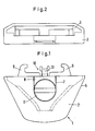
- the razor head 1 of the oscillating head shaver not shown in its entirety, has an outer apparatus body 2 with a front window 3 into which the parts belonging to the actual mounting of the razor blade unit, not shown, can be inserted.
- the outer apparatus body 2 is provided with a razor handle, which is not shown, to be formed in one piece or to be connectable.
- a lower base plate 4 of substantially triangular shape and an upper closure plate 5 form a housing with cross connections and, if necessary, side connections 6.
- the upper closure plate 5 is provided with a wide recess 7 for receiving and guiding a slide 8 which can be pushed forward and which serves the user to bring the receiving forks 9 of a fork holder 10 into an open position for receiving the razor blade unit.
- the slider 8, which can be moved back and forth, is combined with a rotary knob 11, by means of which the user is able to lock a razor blade unit which has been picked up and held by the fork holder 10 by rotating it in a fixing position.
- the rotary knob 11 acts via a locking device 12 arranged below the upper locking plate 5 on a spring cam 13, which is arranged between the receiving forks 9 of the fork holder 10 and can be pressed in by a central rib of the razor blade unit to be inserted, which can be pressed in spring-loaded in the oscillating position and in the locking position to generate a fixed shaving system is blocked by the locking device after a corresponding rotation of the rotary knob 11 in the contact position on the razor blade unit.
- the lower base plate 4 is L-shaped in section and forms with the upper closure plate 5 a housing for holding the rotary knob 11 arranged on the top, combined with the slide 8.
- the housing contains a holder for the receiving forks 9, the spring cams 13 and Various actuating parts that enable the axial displacement of the slider 8 and the rotation of the rotary knob 11 in the sense of receiving, holding and dispensing a vibrating head razor blade unit and locking them by means of the locking device.
- longitudinal guides 14 (FIG. 7), which are arranged parallel to one another on both sides of their center, are formed for the spring cam 13, which ends on the inside in a pin 15, which is the one abutment of a compression spring 16, the other abutment 17 of which is also by means of the slide 8 is arranged axially movable in the guides at the rear end.
- the spring cam 13 is enclosed by the fork holder 10.
- Their receiving forks 9 - as can be seen in FIG. 9 of the drawing - are pivotally mounted on the pivot bearing pin 18 of the lower base plate 9 in opposite directions, the fork arms being designed on the inside in each case as an expanding and stepped curve 19 are best seen in Fig. 3 of the drawing in the dashed line. Via the curve 19, the sliding movement of the slide 8 to the front is implemented in a pivoting movement of the receiving forks 9 outwards into their open position.
- the rear ends of the receiving forks 9 engage behind a recess 20 of the abutment 17, so that this with the Axial displacement of the slide 8 to the front and the resulting pivoting movement of the receiving forks 10 is pressed outward in its longitudinal guides 14, the spring 16 being tensioned.
- the slide 8 In order to achieve the pivoting of the receiving forks 9 into their open position by moving the slide 8 to the front, it is held axially movable in the recess 7 of the upper closure plate by tongue and groove engagement.
- the inner part of the slide 8 encloses the spring cam 13 and forms a guide for the latter, which enables its axial movement to the rear against the action of the compression spring 16.
- a cam 22 On a central axis 21 of the slide 8, which is also the axis of rotation for the knob 11, a cam 22 is formed inside, which cooperates with the curve 19 of the fork bracket 10 so that it opens when the slide 8 is axially moved and in the open position by positive locking is held.
- the locking device 12 consists of the rotary knob 11 which can be rotated into a locking position in the slide 8, on the axis 21 of which a toggle 23 is arranged, which in its fixing position shown in FIG abutment 17 at its rear end presses against its rear stop in the L-shaped part of the base plate 4.
- This locking position is possible by turning the rotary knob out of its normal position into the position of FIG. 8 when the fork holder is in its closed position, ie holds a razor blade unit between its receiving forks 9 in the application.
- FIGS. 6 and 7 of the drawing show the locking device in its inactive position with the rotary knob 11 rotated by 90 °, so that the usual oscillating movement of the razor blade unit in the oscillating head shaver is made possible.
- the spring cam 13 can be moved due to its free backward movement against the action of the compression spring and does not hinder the pivoting of the razor blade unit.
- the alternative embodiment of the razor head 1 shown in FIG. 10 differs from the previously described embodiment in that a lever 28 is provided instead of a rotary button 11 integrated in the slide 8. This is guided out of the inside of the shaver head 1 through a slot 29 on the rear side thereof.
- This embodiment using a lever 28 for locking the spring cam 13 also provides a (not visible) toggle 23 which is arranged on the axis 21 of the lever 28 and comes into engagement with the spring cam 13 during a pivoting movement with the contact surfaces 24. By back pivoting the lever 28, the spring cam 13 is unlocked again, so that the oscillating head razor blade can be pivoted again in the fork holder.
Landscapes
- Life Sciences & Earth Sciences (AREA)
- Forests & Forestry (AREA)
- Engineering & Computer Science (AREA)
- Mechanical Engineering (AREA)
- Dry Shavers And Clippers (AREA)
- Finish Polishing, Edge Sharpening, And Grinding By Specific Grinding Devices (AREA)
- Paper (AREA)
Priority Applications (1)
| Application Number | Priority Date | Filing Date | Title |
|---|---|---|---|
| AT88120849T ATE55566T1 (de) | 1987-12-18 | 1988-12-14 | Schwingkopf-rasierapparat. |
Applications Claiming Priority (2)
| Application Number | Priority Date | Filing Date | Title |
|---|---|---|---|
| DE19873742956 DE3742956A1 (de) | 1987-12-18 | 1987-12-18 | Schwingkopfrasierapparat |
| DE3742956 | 1987-12-18 |
Publications (2)
| Publication Number | Publication Date |
|---|---|
| EP0320892A1 true EP0320892A1 (fr) | 1989-06-21 |
| EP0320892B1 EP0320892B1 (fr) | 1990-08-16 |
Family
ID=6342920
Family Applications (1)
| Application Number | Title | Priority Date | Filing Date |
|---|---|---|---|
| EP88120849A Expired - Lifetime EP0320892B1 (fr) | 1987-12-18 | 1988-12-14 | Rasoir à tête pivotante |
Country Status (7)
| Country | Link |
|---|---|
| US (1) | US4922609A (fr) |
| EP (1) | EP0320892B1 (fr) |
| AT (1) | ATE55566T1 (fr) |
| DE (2) | DE3742956A1 (fr) |
| ES (1) | ES2017007B3 (fr) |
| GR (1) | GR3001079T3 (fr) |
| HK (1) | HK147195A (fr) |
Families Citing this family (13)
| Publication number | Priority date | Publication date | Assignee | Title |
|---|---|---|---|---|
| AU638974B2 (en) * | 1989-06-05 | 1993-07-15 | Warner-Lambert Company | Razor mechanism |
| US5044077A (en) * | 1990-04-10 | 1991-09-03 | Warner-Lambert Company | Razor mechanism |
| US6880253B1 (en) * | 2000-06-23 | 2005-04-19 | Bic Violex S.A. | Razor with a movable shaving head |
| EP1308250A1 (fr) * | 2001-11-01 | 2003-05-07 | Warner-Lambert Company | Ensemble rasoir à cartouche remplaçable |
| US8474144B2 (en) * | 2009-08-12 | 2013-07-02 | The Gillette Company | Safety razor with rotational movement and locking button |
| US8720072B2 (en) | 2010-08-11 | 2014-05-13 | Thomas J. Bucco | Razor with three-axis multi-position capability |
| EP2962815A1 (fr) * | 2014-07-02 | 2016-01-06 | The Gillette Company | Blocage de pivotement de rasoir |
| JP7084915B2 (ja) | 2016-08-24 | 2022-06-15 | エッジウェル パーソナル ケア ブランズ リミテッド ライアビリティ カンパニー | かみそり及び回転部分を有するかみそりハンドル |
| EP3398738B1 (fr) * | 2017-05-05 | 2020-03-11 | BIC Violex S.A. | Manche de rasoir |
| USD948791S1 (en) * | 2019-12-06 | 2022-04-12 | Michael Sopuch | Modular razor cartridge clasp |
| USD935695S1 (en) * | 2020-02-03 | 2021-11-09 | Edgewell Personal Care Brands, Llc | Razor cartridge connector |
| USD935696S1 (en) * | 2020-02-03 | 2021-11-09 | Edgewell Personal Care Brands, Llc | Razor cartridge connector |
| USD935096S1 (en) * | 2020-02-03 | 2021-11-02 | Edgewell Personal Care Brands, Llc | Razor cartridge connector |
Citations (4)
| Publication number | Priority date | Publication date | Assignee | Title |
|---|---|---|---|---|
| US3964160A (en) * | 1975-04-02 | 1976-06-22 | Garron Gordon | Safety razor with an angularly adjustable head |
| GB2066135A (en) * | 1979-12-31 | 1981-07-08 | Warner Lambert Co | Razor handle with latch for piovtable cartridge |
| US4492025A (en) * | 1982-09-17 | 1985-01-08 | The Gillette Company | Razor handle assembly |
| EP0271185A2 (fr) * | 1986-12-08 | 1988-06-15 | Warner-Lambert Company | Rasoir mécanique à tête pivotante avec moyens de blocage de la tête |
Family Cites Families (4)
| Publication number | Priority date | Publication date | Assignee | Title |
|---|---|---|---|---|
| US4083104A (en) * | 1975-05-12 | 1978-04-11 | The Gillette Company | Razor handle |
| NL7809461A (nl) * | 1978-09-18 | 1980-03-20 | Philips Nv | Scheerapparaat. |
| US4266340A (en) * | 1979-06-11 | 1981-05-12 | Warner-Lambert Company | Razor handle for mounting pivotable razor blade cartridges |
| US4756082A (en) * | 1987-05-12 | 1988-07-12 | Apprille Jr Domenic V | Razor blade assembly and handle therefor |
-
1987
- 1987-12-18 DE DE19873742956 patent/DE3742956A1/de not_active Withdrawn
-
1988
- 1988-12-14 EP EP88120849A patent/EP0320892B1/fr not_active Expired - Lifetime
- 1988-12-14 AT AT88120849T patent/ATE55566T1/de not_active IP Right Cessation
- 1988-12-14 DE DE8888120849T patent/DE3860462D1/de not_active Expired - Lifetime
- 1988-12-14 ES ES88120849T patent/ES2017007B3/es not_active Expired - Lifetime
- 1988-12-15 US US07/284,953 patent/US4922609A/en not_active Expired - Lifetime
-
1990
- 1990-11-15 GR GR90400922T patent/GR3001079T3/el unknown
-
1995
- 1995-09-14 HK HK147195A patent/HK147195A/xx not_active IP Right Cessation
Patent Citations (4)
| Publication number | Priority date | Publication date | Assignee | Title |
|---|---|---|---|---|
| US3964160A (en) * | 1975-04-02 | 1976-06-22 | Garron Gordon | Safety razor with an angularly adjustable head |
| GB2066135A (en) * | 1979-12-31 | 1981-07-08 | Warner Lambert Co | Razor handle with latch for piovtable cartridge |
| US4492025A (en) * | 1982-09-17 | 1985-01-08 | The Gillette Company | Razor handle assembly |
| EP0271185A2 (fr) * | 1986-12-08 | 1988-06-15 | Warner-Lambert Company | Rasoir mécanique à tête pivotante avec moyens de blocage de la tête |
Also Published As
| Publication number | Publication date |
|---|---|
| ES2017007B3 (es) | 1990-12-16 |
| ATE55566T1 (de) | 1990-09-15 |
| EP0320892B1 (fr) | 1990-08-16 |
| DE3742956A1 (de) | 1989-06-29 |
| US4922609A (en) | 1990-05-08 |
| GR3001079T3 (en) | 1992-04-17 |
| DE3860462D1 (de) | 1990-09-20 |
| HK147195A (en) | 1995-09-22 |
Similar Documents
| Publication | Publication Date | Title |
|---|---|---|
| DE69314800T2 (de) | Mechanismus für einen rasierhandgriff mit einer konvex-konkav gleitenden stütze für die klingeneinheit | |
| DE69018706T2 (de) | Rasierer-Mechanismus. | |
| EP0302268B1 (fr) | Rasoir électrique avec tête oscillante réglable | |
| EP1671761B1 (fr) | Rasoir mécanique comprenant une cartouche amovible | |
| EP1934021B1 (fr) | Cutter | |
| EP0320892B1 (fr) | Rasoir à tête pivotante | |
| DE3729257C2 (fr) | ||
| DE102016120891A1 (de) | Verschluss für Schusswaffen | |
| DE3414328C2 (de) | Magazinhalteeinrichtung für Pistolen | |
| DE2136724C3 (de) | Sitz mit verstellbarer Rückenlehne | |
| DE2342805A1 (de) | Kraftsteckdose mit schalter und verriegelungsmechanismus | |
| DE2035282A1 (de) | Mit Schließzyhnder ausgerüstetes Lenkschloß | |
| DE3128701C2 (de) | Sperrvorrichtung mit zwei Verriegelungsstiften | |
| DE3006151A1 (de) | Schloss, insbesondere fuer kraftfahrzeug-heckklappentuer | |
| DE3433286A1 (de) | Messer mit feststehender klinge | |
| DE3915728C2 (fr) | ||
| DE102023100423B3 (de) | Auswerferknopf mit integrierter Rückstellfunktion für einen Rasiererhandgriff, Rasiererhandgriff und Nassrasierer | |
| DE2649559C2 (de) | Verschluß für Sicherheitsgurte | |
| DE2927608A1 (de) | Tuerverschluss, inskesondere fuer haushaltsgeraete | |
| DE9407540U1 (de) | Rasierapparatekopf | |
| DE540284C (de) | Zigarrenabschneider | |
| DE2725047A1 (de) | Automatische umschaltvorrichtung fuer wannenfuell- und brausearmaturen o.dgl. | |
| DE8716672U1 (de) | Schwingkopfrasierapparat | |
| DE2710887C2 (de) | Scharnier | |
| DE3036210A1 (de) | Fersenhalter |
Legal Events
| Date | Code | Title | Description |
|---|---|---|---|
| PUAI | Public reference made under article 153(3) epc to a published international application that has entered the european phase |
Free format text: ORIGINAL CODE: 0009012 |
|
| AK | Designated contracting states |
Kind code of ref document: A1 Designated state(s): AT BE CH DE ES FR GB GR IT LI LU NL SE |
|
| 17P | Request for examination filed |
Effective date: 19890628 |
|
| 17Q | First examination report despatched |
Effective date: 19891006 |
|
| GRAA | (expected) grant |
Free format text: ORIGINAL CODE: 0009210 |
|
| AK | Designated contracting states |
Kind code of ref document: B1 Designated state(s): AT BE CH DE ES FR GB GR IT LI LU NL SE |
|
| REF | Corresponds to: |
Ref document number: 55566 Country of ref document: AT Date of ref document: 19900915 Kind code of ref document: T |
|
| ET | Fr: translation filed | ||
| GBT | Gb: translation of ep patent filed (gb section 77(6)(a)/1977) | ||
| ITF | It: translation for a ep patent filed | ||
| REF | Corresponds to: |
Ref document number: 3860462 Country of ref document: DE Date of ref document: 19900920 |
|
| PGFP | Annual fee paid to national office [announced via postgrant information from national office to epo] |
Ref country code: ES Payment date: 19901218 Year of fee payment: 3 |
|
| PGFP | Annual fee paid to national office [announced via postgrant information from national office to epo] |
Ref country code: SE Payment date: 19901219 Year of fee payment: 3 |
|
| PGFP | Annual fee paid to national office [announced via postgrant information from national office to epo] |
Ref country code: AT Payment date: 19901221 Year of fee payment: 3 |
|
| PGFP | Annual fee paid to national office [announced via postgrant information from national office to epo] |
Ref country code: GR Payment date: 19901227 Year of fee payment: 3 Ref country code: LU Payment date: 19901227 Year of fee payment: 3 |
|
| ITTA | It: last paid annual fee | ||
| PG25 | Lapsed in a contracting state [announced via postgrant information from national office to epo] |
Ref country code: LU Free format text: LAPSE BECAUSE OF NON-PAYMENT OF DUE FEES Effective date: 19901231 |
|
| PGFP | Annual fee paid to national office [announced via postgrant information from national office to epo] |
Ref country code: NL Payment date: 19901231 Year of fee payment: 3 |
|
| PGFP | Annual fee paid to national office [announced via postgrant information from national office to epo] |
Ref country code: BE Payment date: 19910114 Year of fee payment: 3 |
|
| PGFP | Annual fee paid to national office [announced via postgrant information from national office to epo] |
Ref country code: CH Payment date: 19910121 Year of fee payment: 3 |
|
| EPTA | Lu: last paid annual fee | ||
| PLBE | No opposition filed within time limit |
Free format text: ORIGINAL CODE: 0009261 |
|
| STAA | Information on the status of an ep patent application or granted ep patent |
Free format text: STATUS: NO OPPOSITION FILED WITHIN TIME LIMIT |
|
| REG | Reference to a national code |
Ref country code: GR Ref legal event code: FG4A Free format text: 3001079 |
|
| 26N | No opposition filed | ||
| PG25 | Lapsed in a contracting state [announced via postgrant information from national office to epo] |
Ref country code: AT Effective date: 19911214 |
|
| PG25 | Lapsed in a contracting state [announced via postgrant information from national office to epo] |
Ref country code: SE Effective date: 19911215 |
|
| PG25 | Lapsed in a contracting state [announced via postgrant information from national office to epo] |
Ref country code: LI Effective date: 19911231 Ref country code: CH Effective date: 19911231 Ref country code: BE Effective date: 19911231 |
|
| BERE | Be: lapsed |
Owner name: WILKINSON SWORD G.M.B.H. Effective date: 19911231 |
|
| PG25 | Lapsed in a contracting state [announced via postgrant information from national office to epo] |
Ref country code: GR Free format text: THE PATENT HAS BEEN ANNULLED BY A DECISION OF A NATIONAL AUTHORITY Effective date: 19920630 |
|
| PG25 | Lapsed in a contracting state [announced via postgrant information from national office to epo] |
Ref country code: NL Effective date: 19920701 |
|
| NLV4 | Nl: lapsed or anulled due to non-payment of the annual fee | ||
| REG | Reference to a national code |
Ref country code: CH Ref legal event code: PL |
|
| PG25 | Lapsed in a contracting state [announced via postgrant information from national office to epo] |
Ref country code: ES Free format text: LAPSE BECAUSE OF NON-PAYMENT OF DUE FEES Effective date: 19921215 |
|
| PGFP | Annual fee paid to national office [announced via postgrant information from national office to epo] |
Ref country code: FR Payment date: 19941209 Year of fee payment: 7 |
|
| REG | Reference to a national code |
Ref country code: GR Ref legal event code: MM2A Free format text: 3001079 |
|
| EUG | Se: european patent has lapsed |
Ref document number: 88120849.0 Effective date: 19920704 |
|
| PG25 | Lapsed in a contracting state [announced via postgrant information from national office to epo] |
Ref country code: FR Effective date: 19960830 |
|
| REG | Reference to a national code |
Ref country code: FR Ref legal event code: ST |
|
| REG | Reference to a national code |
Ref country code: GB Ref legal event code: IF02 |
|
| REG | Reference to a national code |
Ref country code: ES Ref legal event code: FD2A Effective date: 19930113 |
|
| PG25 | Lapsed in a contracting state [announced via postgrant information from national office to epo] |
Ref country code: IT Free format text: LAPSE BECAUSE OF NON-PAYMENT OF DUE FEES;WARNING: LAPSES OF ITALIAN PATENTS WITH EFFECTIVE DATE BEFORE 2007 MAY HAVE OCCURRED AT ANY TIME BEFORE 2007. THE CORRECT EFFECTIVE DATE MAY BE DIFFERENT FROM THE ONE RECORDED. Effective date: 20051214 |
|
| PGFP | Annual fee paid to national office [announced via postgrant information from national office to epo] |
Ref country code: GB Payment date: 20071227 Year of fee payment: 20 |
|
| PGFP | Annual fee paid to national office [announced via postgrant information from national office to epo] |
Ref country code: DE Payment date: 20080131 Year of fee payment: 20 |
|
| REG | Reference to a national code |
Ref country code: GB Ref legal event code: PE20 Expiry date: 20081213 |
|
| PG25 | Lapsed in a contracting state [announced via postgrant information from national office to epo] |
Ref country code: GB Free format text: LAPSE BECAUSE OF EXPIRATION OF PROTECTION Effective date: 20081213 |