EP0320948A1 - Turbine à gaz - Google Patents
Turbine à gaz Download PDFInfo
- Publication number
- EP0320948A1 EP0320948A1 EP88121030A EP88121030A EP0320948A1 EP 0320948 A1 EP0320948 A1 EP 0320948A1 EP 88121030 A EP88121030 A EP 88121030A EP 88121030 A EP88121030 A EP 88121030A EP 0320948 A1 EP0320948 A1 EP 0320948A1
- Authority
- EP
- European Patent Office
- Prior art keywords
- recuperator
- gas turbine
- combustion chamber
- compressor
- turbine plant
- Prior art date
- Legal status (The legal status is an assumption and is not a legal conclusion. Google has not performed a legal analysis and makes no representation as to the accuracy of the status listed.)
- Granted
Links
- 238000002485 combustion reaction Methods 0.000 claims abstract description 23
- 239000000919 ceramic Substances 0.000 claims 1
- 238000010276 construction Methods 0.000 abstract description 3
- 239000012212 insulator Substances 0.000 abstract description 2
- 239000007789 gas Substances 0.000 description 24
- 239000003570 air Substances 0.000 description 10
- 238000009413 insulation Methods 0.000 description 3
- 238000009434 installation Methods 0.000 description 2
- 239000012080 ambient air Substances 0.000 description 1
- 238000001816 cooling Methods 0.000 description 1
- 230000001934 delay Effects 0.000 description 1
- 238000004519 manufacturing process Methods 0.000 description 1
- 239000012528 membrane Substances 0.000 description 1
- 239000002184 metal Substances 0.000 description 1
- 230000002093 peripheral effect Effects 0.000 description 1
- 230000000717 retained effect Effects 0.000 description 1
- 230000003584 silencer Effects 0.000 description 1
- 230000007704 transition Effects 0.000 description 1
Images


Classifications
-
- F—MECHANICAL ENGINEERING; LIGHTING; HEATING; WEAPONS; BLASTING
- F28—HEAT EXCHANGE IN GENERAL
- F28D—HEAT-EXCHANGE APPARATUS, NOT PROVIDED FOR IN ANOTHER SUBCLASS, IN WHICH THE HEAT-EXCHANGE MEDIA DO NOT COME INTO DIRECT CONTACT
- F28D7/00—Heat-exchange apparatus having stationary tubular conduit assemblies for both heat-exchange media, the media being in contact with different sides of a conduit wall
- F28D7/10—Heat-exchange apparatus having stationary tubular conduit assemblies for both heat-exchange media, the media being in contact with different sides of a conduit wall the conduits being arranged one within the other, e.g. concentrically
- F28D7/103—Heat-exchange apparatus having stationary tubular conduit assemblies for both heat-exchange media, the media being in contact with different sides of a conduit wall the conduits being arranged one within the other, e.g. concentrically consisting of more than two coaxial conduits or modules of more than two coaxial conduits
-
- F—MECHANICAL ENGINEERING; LIGHTING; HEATING; WEAPONS; BLASTING
- F01—MACHINES OR ENGINES IN GENERAL; ENGINE PLANTS IN GENERAL; STEAM ENGINES
- F01D—NON-POSITIVE DISPLACEMENT MACHINES OR ENGINES, e.g. STEAM TURBINES
- F01D21/00—Shutting-down of machines or engines, e.g. in emergency; Regulating, controlling, or safety means not otherwise provided for
- F01D21/04—Shutting-down of machines or engines, e.g. in emergency; Regulating, controlling, or safety means not otherwise provided for responsive to undesired position of rotor relative to stator or to breaking-off of a part of the rotor, e.g. indicating such position
- F01D21/045—Shutting-down of machines or engines, e.g. in emergency; Regulating, controlling, or safety means not otherwise provided for responsive to undesired position of rotor relative to stator or to breaking-off of a part of the rotor, e.g. indicating such position special arrangements in stators or in rotors dealing with breaking-off of part of rotor
-
- F—MECHANICAL ENGINEERING; LIGHTING; HEATING; WEAPONS; BLASTING
- F02—COMBUSTION ENGINES; HOT-GAS OR COMBUSTION-PRODUCT ENGINE PLANTS
- F02C—GAS-TURBINE PLANTS; AIR INTAKES FOR JET-PROPULSION PLANTS; CONTROLLING FUEL SUPPLY IN AIR-BREATHING JET-PROPULSION PLANTS
- F02C7/00—Features, components parts, details or accessories, not provided for in, or of interest apart form groups F02C1/00 - F02C6/00; Air intakes for jet-propulsion plants
- F02C7/08—Heating air supply before combustion, e.g. by exhaust gases
Definitions
- the invention relates to a gas turbine system of the type specified in the preamble of the first claim.
- recuperators have the disadvantage that they are relatively large, so that they increase the installation volume of the gas turbine system.
- the generic gas turbine system is known from US Pat. No. 2,633,338.
- the ring-shaped recuperator encloses the compressor and the compressor turbine as well as the combustion chamber.
- Nothing is known about the arrangement of a power turbine with a necessary reduction gear.
- a disadvantage of this arrangement it is that the compressor is also enclosed by the recuperator and can therefore become too warm.
- the structure of the recuperator made of sheet metal described there is far too expensive to manufacture and too susceptible to damage because of the necessary soldered connections.
- the object of the invention is to propose a gas turbine system with a recuperator which is small due to its installation volume.
- this object is achieved by the characterizing features of the first claim.
- This solution has the advantage that by combing the combustion chamber and the heat exchanger, the heat exchanger insulates the combustion chamber from the outside, so that the heat loss from the combustion chamber remains largely in the gas turbine system and is therefore useful.
- weight can be saved in this way because the outer wall of the combustion chamber can be dispensed with and its function can be taken over by the outer wall of the heat exchanger.
- the heat exchanger arrangement thus created can also serve as a burst protection for the combustion chamber and turbine impellers, so that the walls thereof can be made simpler or lighter.
- this also further increases the function of the heat insulation of the heat exchanger, because now the Heat loss from the turbine is largely retained in the system and is therefore used to increase the temperature of the combustion air.
- this arrangement has the advantage that the heat exchanger can also function as a soundproofing body for the loudest sections of the gas turbine system.
- the compressor, which is not part of the hot parts, and any reduction gear behind the utility turbine are not enclosed by the recuperator. They can therefore also be cooled well or are not heated unnecessarily.
- Claim 2 describes a preferred construction of the heat exchanger.
- a particularly compact heat exchanger is achieved if at least two pipes are pushed into one another and the individual pipe pairs are arranged on concentric circles.
- the advantage is achieved that thermal insulation of the heat exchanger can be achieved by the outside air around without additional means.
- Claim 4 describes a compact and very well thermally insulated structure of the gas turbine system for a vehicle drive.
- the gas turbine system consists of a compressor 1 which draws in ambient air and compresses it via a line 2 to an annular recuperator 3 which works according to the counterflow principle.
- the compressed air flows through it and is heated by the hot gases.
- the compressed air heated in this way reaches an annular combustion chamber 4, which is constructed as a two-stage annular combustion chamber.
- the hot gases generated there flow from the combustion chamber outlet into the compressor turbine 5 and the utility turbine 6. From there, the hot gases pass via the likewise annular line 7 to the recuperator 3, which they leave via the line 8.
- conventional silencer devices can be provided.
- the peripheral edges have been omitted in FIG. 1 for a better overview.
- the power turbine 6 is connected to a reduction gear 9, on the output shaft 10 of which - when using the gas turbine system as a vehicle drive - a drive gear is arranged.
- the entire gas turbine system with its individual elements is arranged concentrically around a common central longitudinal axis 11.
- the shafts of the compressor 1 and the two turbines 5 and 6 as well as the longitudinal axis of the annular combustion chamber 4 and of the recuperator 3 surrounding them lie on this common longitudinal axis.
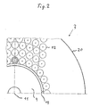
- the recuperator 3 encloses both the combustion chamber 4 and the compressor turbine 5 and the power turbine 6 in a cylindrical shape. On the one hand, it acts as a heat insulator for the hottest parts of the gas turbine system. On the other hand, it can act as a burst protection, in particular for the two turbine impellers. Because of this arrangement the transition channels from the turbine outlet to the heat exchanger inlet are relatively short and can be designed with very little construction so that the flow delays are each associated with relatively low losses. The heat insulation to the outside can also be achieved with this arrangement if the line 2 in the area of the recuperator 3 is ring-shaped and thus surrounds the recuperator from the outside as a cylinder or partial cylinder.
- the recuperator 3 itself is designed as a counterflow heat exchanger and has a multiplicity of thin-walled tubes 12, 13 and 14 with stepped diameters (FIGS. 2, 3). As clearly shown in FIG. 2 in particular, the individual tubes 12-14 are arranged with their longitudinal axes coaxial and within the recuperator 3 on concentric circles to the longitudinal axis 11 thereof. This creates a very dense design with sufficiently large heat exchanger contact areas. The individual tubes 12-14 are held one above the other via inner webs 15. The recuperator 3 is thus constructed from a multiplicity of cylindrical tubes (multicylinder), which in turn each consist of three individual tubes pushed into one another.
- multicylinder multicylinder
- FIG. 3 An end view of such three individual tubes 12-14 is shown in FIG. 3.
- the tube 14 and the remaining annular gap between the tube outer diameter 13 and the tube inner diameter 12 are used to guide the hot gases after they have left the utility turbine.
- the annular gap between the tube outer diameter of the tube 14 and the tube inner diameter of the tube 13 serves to guide the compressed air to be heated.
- retaining washers 16, 17 and 18 are provided in their end region, in which they are tightly and elastically fastened. These retaining washers act as a membrane, so that they can easily allow the thermal expansion that occurs without causing stress peaks on the pipe or retaining washer side. In addition, this may lead to leakage air at the joining and assembly points of the combustion chamber and does not flow as a loss to the outside or to places in the gas turbine system where it can impair its function.
- collecting or distribution channels are formed between the individual holding disks, which can serve for supplying and removing the hot gas or the air to be heated.
- the recuperator 3 also has inner and outer walls 19 and 20 in addition to the holding disks (FIG. 3).
- additional guide channels for the compressed, heated air from the recuperator 3 to the combustion chamber 4 can be avoided if in the region of the end of the combustion chamber and in the region of the turbines (compressor turbine 5 or utility turbine 6) there is also an end wall - in FIGS. 1 with 21 and 22 designated - is provided.
- the end wall in the region of the turbines can also be replaced by the annular hot gas line 7.
Landscapes
- Engineering & Computer Science (AREA)
- Mechanical Engineering (AREA)
- General Engineering & Computer Science (AREA)
- Chemical & Material Sciences (AREA)
- Combustion & Propulsion (AREA)
- Physics & Mathematics (AREA)
- Thermal Sciences (AREA)
- Heat-Exchange Devices With Radiators And Conduit Assemblies (AREA)
Applications Claiming Priority (2)
| Application Number | Priority Date | Filing Date | Title |
|---|---|---|---|
| DE19873742892 DE3742892A1 (de) | 1987-12-17 | 1987-12-17 | Gasturbinenanlage |
| DE3742892 | 1987-12-17 |
Publications (3)
| Publication Number | Publication Date |
|---|---|
| EP0320948A1 true EP0320948A1 (fr) | 1989-06-21 |
| EP0320948B1 EP0320948B1 (fr) | 1991-10-16 |
| EP0320948B2 EP0320948B2 (fr) | 1996-06-19 |
Family
ID=6342884
Family Applications (1)
| Application Number | Title | Priority Date | Filing Date |
|---|---|---|---|
| EP88121030A Expired - Lifetime EP0320948B2 (fr) | 1987-12-17 | 1988-12-15 | Turbine à gaz |
Country Status (3)
| Country | Link |
|---|---|
| EP (1) | EP0320948B2 (fr) |
| DE (2) | DE3742892A1 (fr) |
| ES (1) | ES2026989T5 (fr) |
Cited By (4)
| Publication number | Priority date | Publication date | Assignee | Title |
|---|---|---|---|---|
| FR2883367A1 (fr) * | 2005-03-15 | 2006-09-22 | Pierre Bignon | Echangeur thermique |
| WO2008015314A1 (fr) * | 2006-08-02 | 2008-02-07 | Pierre Bignon | Echangeur thermique |
| CN100535569C (zh) * | 2007-09-07 | 2009-09-02 | 浙江海峰制鞋设备有限公司 | 套筒式换热器 |
| FR3144187A1 (fr) * | 2022-12-23 | 2024-06-28 | Safran Helicopter Engines | Turbomachine comprenant des moyens de blindage economiques. |
Families Citing this family (4)
| Publication number | Priority date | Publication date | Assignee | Title |
|---|---|---|---|---|
| DE4335136C2 (de) * | 1992-10-22 | 1999-12-16 | Alstom Energy Syst Gmbh | Verfahren und Vorrichtung zur Durchführung des Verfahrens zur Erzeugung von Gasen zum Betreiben einer Gasturbine in einem kombinierten Gas- und Dampfkraftwerk |
| DE19525298A1 (de) * | 1995-07-12 | 1997-02-27 | Christian Kurpiers | Dampf-Gas-Turbine |
| RU2154181C1 (ru) * | 1999-02-22 | 2000-08-10 | Косарев Александр Владимирович | Газотурбинная установка |
| RU2210679C2 (ru) * | 1999-03-24 | 2003-08-20 | Открытое акционерное общество Научно-производственное объединение "Искра" | Система подогрева воздуха в агрегатах с газотурбинным двигателем |
Citations (6)
| Publication number | Priority date | Publication date | Assignee | Title |
|---|---|---|---|---|
| FR1003131A (fr) * | 1946-12-07 | 1952-03-14 | Perfectionnements apportés aux ensembles devant comporter un échangeur thermique, notamment aux groupes turbo-moteurs à compression et réchauffage préalables | |
| US2633338A (en) * | 1947-02-19 | 1953-03-31 | Continental Aviat & Engineerin | Heat exchanger |
| DE1023276B (de) * | 1954-11-13 | 1958-01-23 | Vlastimir Davidovitch Dipl Ing | Gasturbine |
| US3831374A (en) * | 1971-08-30 | 1974-08-27 | Power Technology Corp | Gas turbine engine and counterflow heat exchanger with outer air passageway |
| DE2618025A1 (de) * | 1976-04-24 | 1977-11-10 | Erich Tausend | Gasturbine mit hohlrippenzylinder- vorerhitzer |
| GB2005355A (en) * | 1977-10-06 | 1979-04-19 | Kernforschungsanlage Juelich | Gas turbine unit |
Family Cites Families (2)
| Publication number | Priority date | Publication date | Assignee | Title |
|---|---|---|---|---|
| DE2707290C3 (de) * | 1977-02-19 | 1979-09-20 | Kernforschungsanlage Juelich Gmbh, 5170 Juelich | Rekuperativer Wärmeübertrager aus keramischem Material |
| DE2712136C3 (de) * | 1977-03-19 | 1980-11-20 | Kernforschungsanlage Juelich Gmbh, 5170 Juelich | Gasturbinenanlage für den Antrieb von Fahrzeugen |
-
1987
- 1987-12-17 DE DE19873742892 patent/DE3742892A1/de active Granted
-
1988
- 1988-12-15 EP EP88121030A patent/EP0320948B2/fr not_active Expired - Lifetime
- 1988-12-15 DE DE8888121030T patent/DE3865650D1/de not_active Expired - Lifetime
- 1988-12-15 ES ES88121030T patent/ES2026989T5/es not_active Expired - Lifetime
Patent Citations (6)
| Publication number | Priority date | Publication date | Assignee | Title |
|---|---|---|---|---|
| FR1003131A (fr) * | 1946-12-07 | 1952-03-14 | Perfectionnements apportés aux ensembles devant comporter un échangeur thermique, notamment aux groupes turbo-moteurs à compression et réchauffage préalables | |
| US2633338A (en) * | 1947-02-19 | 1953-03-31 | Continental Aviat & Engineerin | Heat exchanger |
| DE1023276B (de) * | 1954-11-13 | 1958-01-23 | Vlastimir Davidovitch Dipl Ing | Gasturbine |
| US3831374A (en) * | 1971-08-30 | 1974-08-27 | Power Technology Corp | Gas turbine engine and counterflow heat exchanger with outer air passageway |
| DE2618025A1 (de) * | 1976-04-24 | 1977-11-10 | Erich Tausend | Gasturbine mit hohlrippenzylinder- vorerhitzer |
| GB2005355A (en) * | 1977-10-06 | 1979-04-19 | Kernforschungsanlage Juelich | Gas turbine unit |
Cited By (5)
| Publication number | Priority date | Publication date | Assignee | Title |
|---|---|---|---|---|
| FR2883367A1 (fr) * | 2005-03-15 | 2006-09-22 | Pierre Bignon | Echangeur thermique |
| WO2008015314A1 (fr) * | 2006-08-02 | 2008-02-07 | Pierre Bignon | Echangeur thermique |
| CN101568789B (zh) * | 2006-08-02 | 2011-07-27 | 皮埃尔·比尼翁 | 热交换器 |
| CN100535569C (zh) * | 2007-09-07 | 2009-09-02 | 浙江海峰制鞋设备有限公司 | 套筒式换热器 |
| FR3144187A1 (fr) * | 2022-12-23 | 2024-06-28 | Safran Helicopter Engines | Turbomachine comprenant des moyens de blindage economiques. |
Also Published As
| Publication number | Publication date |
|---|---|
| DE3742892C2 (fr) | 1989-10-12 |
| EP0320948B2 (fr) | 1996-06-19 |
| DE3742892A1 (de) | 1989-06-29 |
| ES2026989T3 (es) | 1992-05-16 |
| EP0320948B1 (fr) | 1991-10-16 |
| DE3865650D1 (de) | 1991-11-21 |
| ES2026989T5 (es) | 1996-10-01 |
Similar Documents
| Publication | Publication Date | Title |
|---|---|---|
| DE2949522C2 (de) | Gekühlte Schubdüse für ein Raketentriebwerk | |
| EP0125572B1 (fr) | Brûleur polycombustible | |
| DE69609324T2 (de) | Kombinierter wärmetauscher und schalldämpfer | |
| DE1426648C3 (de) | Schnelldampferzeuger | |
| DE4006982C2 (de) | Gasturbinentriebwerk | |
| EP2839135A1 (fr) | Microturbine à gaz équipée d'un récupérateur de forme tubulaire | |
| DE3742892C2 (fr) | ||
| DE3813202A1 (de) | Waermetauscher | |
| EP0179233A1 (fr) | Machine à ondes de pression travaillant comme échangeur de pression, spécialement pour utilisation comme compresseur d'alimentation en haute pression pour turbine à gaz | |
| DE1060666B (de) | Kraftanlage mit in geschlossenem Kreislauf arbeitendem Gasturbinenaggregat | |
| DE2536657A1 (de) | Waermeaustauscher | |
| DE1266056B (de) | Gasturbinentriebwerk | |
| EP0128463A2 (fr) | Appareil de chauffage des locaux pour des locaux de petite dimension | |
| EP0315098A1 (fr) | Echangeur de chaleur pour chauffer des liquides | |
| DE4118786C2 (de) | Gaslaser, insbesondere Axialstromgaslaser | |
| DE102010032324A1 (de) | Wärmetauscher, Anordnung von Wärmetauschern sowie Gasturbinentriebwerk mit Wärmetauscher oder Anordnung solcher | |
| DE1476773A1 (de) | Rekuperativeinrichtung fuer ein Gasturbinentriebwerk | |
| DE1626120C3 (de) | Gasturbinentriebwerk | |
| DE2628326B2 (de) | Gasturbinenanlage, insbesondere für Kraftfahrzeuge, wie Ackerschlepper | |
| DE963753C (de) | Zwillingsstrahltriebwerk mit quer zur Flugrichtung liegender gemeinsamer Achse | |
| DE949478C (de) | Roehrenlufterhitzer mit Gegenstromprinzip | |
| DE2903764A1 (de) | Kuehlvorrichtung fuer insbesondere fluessigkeitsgekuehlte verbrennungskraftmaschinen fuer nutzfahrzeuge u.dgl. | |
| DE1023276B (de) | Gasturbine | |
| DE950547C (de) | Ammoniakverbrennungsofen mit Abhitzeverwertung | |
| EP4015935B1 (fr) | Collecteur solaire |
Legal Events
| Date | Code | Title | Description |
|---|---|---|---|
| PUAI | Public reference made under article 153(3) epc to a published international application that has entered the european phase |
Free format text: ORIGINAL CODE: 0009012 |
|
| AK | Designated contracting states |
Kind code of ref document: A1 Designated state(s): DE ES FR GB IT SE |
|
| 17P | Request for examination filed |
Effective date: 19890704 |
|
| 17Q | First examination report despatched |
Effective date: 19900615 |
|
| GRAA | (expected) grant |
Free format text: ORIGINAL CODE: 0009210 |
|
| AK | Designated contracting states |
Kind code of ref document: B1 Designated state(s): DE ES FR GB IT SE |
|
| ET | Fr: translation filed | ||
| GBT | Gb: translation of ep patent filed (gb section 77(6)(a)/1977) | ||
| REF | Corresponds to: |
Ref document number: 3865650 Country of ref document: DE Date of ref document: 19911121 |
|
| ITF | It: translation for a ep patent filed | ||
| REG | Reference to a national code |
Ref country code: ES Ref legal event code: FG2A Ref document number: 2026989 Country of ref document: ES Kind code of ref document: T5 |
|
| PLBI | Opposition filed |
Free format text: ORIGINAL CODE: 0009260 |
|
| 26 | Opposition filed |
Opponent name: MTU MOTOREN- UND TURBINEN-UNION MUENCHEN GMBH Effective date: 19920716 |
|
| RAP4 | Party data changed (patent owner data changed or rights of a patent transferred) |
Owner name: BAYERISCHE MOTOREN WERKE AKTIENGESELLSCHAFT |
|
| EAL | Se: european patent in force in sweden |
Ref document number: 88121030.6 |
|
| PGFP | Annual fee paid to national office [announced via postgrant information from national office to epo] |
Ref country code: ES Payment date: 19951213 Year of fee payment: 8 |
|
| PLAW | Interlocutory decision in opposition |
Free format text: ORIGINAL CODE: EPIDOS IDOP |
|
| PUAH | Patent maintained in amended form |
Free format text: ORIGINAL CODE: 0009272 |
|
| STAA | Information on the status of an ep patent application or granted ep patent |
Free format text: STATUS: PATENT MAINTAINED AS AMENDED |
|
| 27A | Patent maintained in amended form |
Effective date: 19960619 |
|
| AK | Designated contracting states |
Kind code of ref document: B2 Designated state(s): DE ES FR GB IT SE |
|
| ET3 | Fr: translation filed ** decision concerning opposition | ||
| GBTA | Gb: translation of amended ep patent filed (gb section 77(6)(b)/1977) |
Effective date: 19960619 |
|
| ITF | It: translation for a ep patent filed | ||
| REG | Reference to a national code |
Ref country code: ES Ref legal event code: DC2A Kind code of ref document: T5 Effective date: 19960807 |
|
| REG | Reference to a national code |
Ref country code: ES Ref legal event code: DC2A Kind code of ref document: T5 Effective date: 19960807 |
|
| PGFP | Annual fee paid to national office [announced via postgrant information from national office to epo] |
Ref country code: SE Payment date: 19961125 Year of fee payment: 9 |
|
| PGFP | Annual fee paid to national office [announced via postgrant information from national office to epo] |
Ref country code: GB Payment date: 19961209 Year of fee payment: 9 |
|
| PGFP | Annual fee paid to national office [announced via postgrant information from national office to epo] |
Ref country code: FR Payment date: 19961230 Year of fee payment: 9 |
|
| PG25 | Lapsed in a contracting state [announced via postgrant information from national office to epo] |
Ref country code: GB Free format text: LAPSE BECAUSE OF NON-PAYMENT OF DUE FEES Effective date: 19971215 |
|
| PG25 | Lapsed in a contracting state [announced via postgrant information from national office to epo] |
Ref country code: SE Free format text: LAPSE BECAUSE OF NON-PAYMENT OF DUE FEES Effective date: 19971216 Ref country code: ES Free format text: LAPSE BECAUSE OF NON-PAYMENT OF DUE FEES Effective date: 19971216 |
|
| PG25 | Lapsed in a contracting state [announced via postgrant information from national office to epo] |
Ref country code: FR Free format text: THE PATENT HAS BEEN ANNULLED BY A DECISION OF A NATIONAL AUTHORITY Effective date: 19971231 |
|
| GBPC | Gb: european patent ceased through non-payment of renewal fee |
Effective date: 19971215 |
|
| EUG | Se: european patent has lapsed |
Ref document number: 88121030.6 |
|
| REG | Reference to a national code |
Ref country code: FR Ref legal event code: ST |
|
| PGFP | Annual fee paid to national office [announced via postgrant information from national office to epo] |
Ref country code: DE Payment date: 20000128 Year of fee payment: 12 |
|
| PG25 | Lapsed in a contracting state [announced via postgrant information from national office to epo] |
Ref country code: DE Free format text: LAPSE BECAUSE OF NON-PAYMENT OF DUE FEES Effective date: 20011002 |
|
| REG | Reference to a national code |
Ref country code: ES Ref legal event code: FD2A Effective date: 19990114 |
|
| PG25 | Lapsed in a contracting state [announced via postgrant information from national office to epo] |
Ref country code: IT Free format text: LAPSE BECAUSE OF NON-PAYMENT OF DUE FEES;WARNING: LAPSES OF ITALIAN PATENTS WITH EFFECTIVE DATE BEFORE 2007 MAY HAVE OCCURRED AT ANY TIME BEFORE 2007. THE CORRECT EFFECTIVE DATE MAY BE DIFFERENT FROM THE ONE RECORDED. Effective date: 20051215 |