EP0321013A2 - Internes Korrosionsinspektions-Verfahren und Vorrichtung für Rohre und Leitungen, deren lichte Weite relativ klein ist - Google Patents
Internes Korrosionsinspektions-Verfahren und Vorrichtung für Rohre und Leitungen, deren lichte Weite relativ klein ist Download PDFInfo
- Publication number
- EP0321013A2 EP0321013A2 EP88202714A EP88202714A EP0321013A2 EP 0321013 A2 EP0321013 A2 EP 0321013A2 EP 88202714 A EP88202714 A EP 88202714A EP 88202714 A EP88202714 A EP 88202714A EP 0321013 A2 EP0321013 A2 EP 0321013A2
- Authority
- EP
- European Patent Office
- Prior art keywords
- probe
- tube
- capacitance
- tubes
- tube wall
- Prior art date
- Legal status (The legal status is an assumption and is not a legal conclusion. Google has not performed a legal analysis and makes no representation as to the accuracy of the status listed.)
- Withdrawn
Links
Images


Classifications
-
- G—PHYSICS
- G01—MEASURING; TESTING
- G01N—INVESTIGATING OR ANALYSING MATERIALS BY DETERMINING THEIR CHEMICAL OR PHYSICAL PROPERTIES
- G01N27/00—Investigating or analysing materials by the use of electric, electrochemical, or magnetic means
- G01N27/02—Investigating or analysing materials by the use of electric, electrochemical, or magnetic means by investigating impedance
- G01N27/22—Investigating or analysing materials by the use of electric, electrochemical, or magnetic means by investigating impedance by investigating capacitance
- G01N27/24—Investigating the presence of flaws
-
- G—PHYSICS
- G01—MEASURING; TESTING
- G01B—MEASURING LENGTH, THICKNESS OR SIMILAR LINEAR DIMENSIONS; MEASURING ANGLES; MEASURING AREAS; MEASURING IRREGULARITIES OF SURFACES OR CONTOURS
- G01B7/00—Measuring arrangements characterised by the use of electric or magnetic techniques
- G01B7/12—Measuring arrangements characterised by the use of electric or magnetic techniques for measuring diameters
- G01B7/13—Internal diameters
-
- G—PHYSICS
- G01—MEASURING; TESTING
- G01B—MEASURING LENGTH, THICKNESS OR SIMILAR LINEAR DIMENSIONS; MEASURING ANGLES; MEASURING AREAS; MEASURING IRREGULARITIES OF SURFACES OR CONTOURS
- G01B7/00—Measuring arrangements characterised by the use of electric or magnetic techniques
- G01B7/28—Measuring arrangements characterised by the use of electric or magnetic techniques for measuring contours or curvatures
- G01B7/287—Measuring arrangements characterised by the use of electric or magnetic techniques for measuring contours or curvatures using a plurality of fixed, simultaneously operating transducers
Definitions
- the invention relates to a method and apparatus for internal corrosion inspection of pipes or tubes of relatively small diameter, such as, for example, used in heat exchangers, flow lines and the like.
- the steel wall of such a tube or pipe may be subject to internal corrosion. This is dependent, obviously, on the matter that is transported through the tube or pipe. Both liquids and gases may attack the steel wall.
- Two forms of corrosion may be of interest, namely uniform corrosion and pitting.
- uniform corrosion the wall thickness decreases more or less uniformly and it will be clear that this could lead to the tube becoming unserviceable, because the wall will become too weak to resist the internal pressure. Pitting could lead to leakage and this phenomenon must also be avoided.
- the disadvantage of using mechanical calipers to detect a general thinning of the wall is that only the first few centimetres of a tube are inspected. Inspection by means of a piglet gives an indication of the complete circumference of the pipes as a function of the distance along the tube. This indication can relate to a general thinning of the wall or to a localized pit, but it is impossible to discriminate between these two phenomena, let alone quantify the pit depths.
- the most commonly used method for inspection of a "complete pipe" is either the ultrasonic technique or the eddy current technique.
- the invention therefore provides a method for internal inspection of pipes or tubes of relatively small diameter characterized by the steps of moving a probe through the tube to be inspected; measuring the capacitance between a first means located on the probe and the tube wall functioning as a second means; monitoring signals representing changes in capacitance which will result from a varying gap between the said first and second means, and deriving from the signals thus obtained information concerning the internal condition of the tube or pipe.
- the invention also provides an apparatus for internal inspection of pipes or tubes of a relatively small diameter characterized by a probe system adapted to be moved through the tube to be inspected; means for measuring the capacitance between a first means mounted on the probe and the tube wall functioning as a second means, means for monitoring signals representing a change of capacitance between the said tube wall and the said means on the probe, and means for deriving information concerning the internal condition of the tube wall from the signals thus obtained.
- the said first and second means are capacitor plates.
- the principle of the invention is based on a capacitive technique.
- the tube wall itself will function as a first capacitive means and the probe should contain one or more second capacitive means.
- the gap between the first and second capacitive means will vary depending on the condition of the tube wall.
- the capacitance between the said first and second means will change, which change can be monitored in any suitable manner.
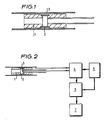
- the probe system comprises a probe body 1 which in any suitable manner is provided with a first capacitive means 2.
- the probe body 1 fits close into a pipe or tube to be inspected.
- the tube wall which functions as a second capacitive means has been represented by the reference numeral 3.
- the capacitive means are connected in any way suitable for the purpose to a detection system which in fig. 1 has not been shown for reasons of clarity and will be described in more detail in fig. 2.
- the first capacitive means is a cylindrical capacitor plate; the probe body 1 can for example be machined out of teflon and may have a length of about 50 mm and a diameter of about 19.5 mm.
- the first capacitor plate can be made out of copper and may be 18.5 mm in diameter with a length of 10 mm.
- the average internal diameter of the tube is for example 20 mm.
- the first capacitor plate 2 is connected in any suitable manner (for example a coaxial cable) to one of the terminals of a capacitance bridge 4.
- the other terminal thereof is connected, also, for example, via a coaxial cable, to the tube wall 3.
- the capacitance bridge 4 is used to compensate for the equilibrium capacitance of the probe system in the tube.
- the capacitance changes are measured in any suitable manner, for example using a phase sensitive detection technique using an oscillator 5 and a lock-in amplifier 6.
- these capacitance changes are displayed in any way suitable for the purpose for example on a chart recorder 7.
- Fig. 3 represents the variation of the internal tube diameter (vertical axis) as a function of the distance along the tube (horizontal axis).
- the actual length covered in the experiments was 32 cm and the length of the tubes was 36 cm.
- the results are for an undamaged - as-received - tube measured with the embodiment of figs. 1 and 2. These measurements have been obtained in a step-wise manner.
- Fig. 4 represents the variation of the internal diameter (vertical axis) as a function of the distance (horizontal axis) along a tube Z (fig. 4 (top)) containing slots with various depths, at the locations A to E, measured with the embodiment of figs. 1 and 2.
- LOCATION WIDTH ACTUAL DEPTH (mm)
- MEASURED DEPTH mm
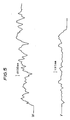
- Fig. 5 represents the results of measurements with another advantageous embodiment of the invention on a naturally corroded tube. Due to excentricity of the probe system in the pipe under inspection the sensitivity is different for the top and bottom plates (V and W respectively). The capacitance measurements were not hindered by the presence of debris.
- the first (cylindrical) capacitor plate in the probe has been replaced by a plurality of plates (for example 6) equally divided around the circumference of the probe.
- the capacitor plates can be surrounded by a plurality (for example 2) (cylindrical) guard rings parallel to the said capacitor plates to obtain a better defined capacitance.
- the diameter of the probe can be reduced to about 18.0 mm in order to be able to travel through highly corroded test tubes.
- the probe body can be provided with springs to provide a better alignment of the probe body in the tubes.
- a switching circuit was required to connect the (six) capacitor plates to the capacitance bridge sequentially and simultaneously connecting the other plates to the guarding potential.
- the first capacitive means of the apparatus of the invention can have any suitable shape and is not necessarily cylindrical.
Landscapes
- Physics & Mathematics (AREA)
- General Physics & Mathematics (AREA)
- Chemical & Material Sciences (AREA)
- Chemical Kinetics & Catalysis (AREA)
- Electrochemistry (AREA)
- Health & Medical Sciences (AREA)
- Life Sciences & Earth Sciences (AREA)
- Analytical Chemistry (AREA)
- Biochemistry (AREA)
- General Health & Medical Sciences (AREA)
- Immunology (AREA)
- Pathology (AREA)
- Investigating Or Analyzing Materials By The Use Of Electric Means (AREA)
- Investigating Or Analyzing Materials By The Use Of Magnetic Means (AREA)
Applications Claiming Priority (2)
| Application Number | Priority Date | Filing Date | Title |
|---|---|---|---|
| GB878728063A GB8728063D0 (en) | 1987-12-01 | 1987-12-01 | Method & apparatus for internal corrosion-inspection of pipes/tubes of relatively small diameter |
| GB8728063 | 1987-12-01 |
Publications (2)
| Publication Number | Publication Date |
|---|---|
| EP0321013A2 true EP0321013A2 (de) | 1989-06-21 |
| EP0321013A3 EP0321013A3 (de) | 1989-07-05 |
Family
ID=10627793
Family Applications (1)
| Application Number | Title | Priority Date | Filing Date |
|---|---|---|---|
| EP88202714A Withdrawn EP0321013A3 (de) | 1987-12-01 | 1988-11-28 | Internes Korrosionsinspektions-Verfahren und Vorrichtung für Rohre und Leitungen, deren lichte Weite relativ klein ist |
Country Status (4)
| Country | Link |
|---|---|
| EP (1) | EP0321013A3 (de) |
| JP (1) | JPH01201151A (de) |
| AU (1) | AU2637288A (de) |
| GB (1) | GB8728063D0 (de) |
Cited By (6)
| Publication number | Priority date | Publication date | Assignee | Title |
|---|---|---|---|---|
| FR2659438A1 (fr) * | 1990-03-07 | 1991-09-13 | Electricite De France | Dispositif et procede de mesure du profil de la paroi interne d'un tube par mesure capacitive. |
| US5864229A (en) * | 1991-06-11 | 1999-01-26 | Millstrong Limited | Eddy current probe system and method for determining the midpoint and depth of a discontinuity |
| RU2172488C1 (ru) * | 1999-12-06 | 2001-08-20 | Саратовский государственный технический университет | Снаряд-дефектоскоп для контроля отверстий в стенках внутри трубопровода |
| GB2408340A (en) * | 2003-11-18 | 2005-05-25 | Radiodetection Ltd | A vehicle for inspecting a pipe |
| RU2265816C2 (ru) * | 2003-09-01 | 2005-12-10 | "Газприборавтоматикасервис" (ГПАС) | Снаряд-дефектоскоп для контроля отверстий в стенках внутри трубопровода |
| WO2015016742A1 (ru) * | 2013-07-30 | 2015-02-05 | Открытое акционерное общество "Акционерная компания по транспорту нефти "Транснефть" (ОАО "АК "Транснефть") | Магнитная измерительная система для дефектоскопа с продольным намагничиванием |
Family Cites Families (4)
| Publication number | Priority date | Publication date | Assignee | Title |
|---|---|---|---|---|
| DE1248956B (de) * | 1967-08-31 | |||
| FR2202586A5 (de) * | 1972-10-06 | 1974-05-03 | Commissariat Energie Atomique | |
| GB2015165B (en) * | 1978-02-09 | 1983-01-12 | Koa Oil Co Ltd | Detecting capacitively corrosion of pipes |
| EP0067643A3 (de) * | 1981-06-12 | 1983-02-09 | Peter Caleb Frederick Wolfendale | Verfahren zur Feststellung der Dimensionen und/oder der Gestalt von Oberflächen |
-
1987
- 1987-12-01 GB GB878728063A patent/GB8728063D0/en active Pending
-
1988
- 1988-11-28 EP EP88202714A patent/EP0321013A3/de not_active Withdrawn
- 1988-11-29 JP JP30212888A patent/JPH01201151A/ja active Pending
- 1988-11-29 AU AU26372/88A patent/AU2637288A/en not_active Abandoned
Cited By (7)
| Publication number | Priority date | Publication date | Assignee | Title |
|---|---|---|---|---|
| FR2659438A1 (fr) * | 1990-03-07 | 1991-09-13 | Electricite De France | Dispositif et procede de mesure du profil de la paroi interne d'un tube par mesure capacitive. |
| US5864229A (en) * | 1991-06-11 | 1999-01-26 | Millstrong Limited | Eddy current probe system and method for determining the midpoint and depth of a discontinuity |
| RU2172488C1 (ru) * | 1999-12-06 | 2001-08-20 | Саратовский государственный технический университет | Снаряд-дефектоскоп для контроля отверстий в стенках внутри трубопровода |
| RU2265816C2 (ru) * | 2003-09-01 | 2005-12-10 | "Газприборавтоматикасервис" (ГПАС) | Снаряд-дефектоскоп для контроля отверстий в стенках внутри трубопровода |
| GB2408340A (en) * | 2003-11-18 | 2005-05-25 | Radiodetection Ltd | A vehicle for inspecting a pipe |
| WO2015016742A1 (ru) * | 2013-07-30 | 2015-02-05 | Открытое акционерное общество "Акционерная компания по транспорту нефти "Транснефть" (ОАО "АК "Транснефть") | Магнитная измерительная система для дефектоскопа с продольным намагничиванием |
| EA031338B1 (ru) * | 2013-07-30 | 2018-12-28 | Публичное Акционерное Общество "Транснефть" | Магнитная измерительная система для дефектоскопа с продольным намагничиванием |
Also Published As
| Publication number | Publication date |
|---|---|
| EP0321013A3 (de) | 1989-07-05 |
| GB8728063D0 (en) | 1988-01-06 |
| JPH01201151A (ja) | 1989-08-14 |
| AU2637288A (en) | 1989-06-01 |
Similar Documents
| Publication | Publication Date | Title |
|---|---|---|
| US4295092A (en) | Apparatus for and method of detecting and measuring corrosion damage in pipe | |
| AU595748B2 (en) | Magnetic flux leakage probe with radially offset coils for use in nondestructives testing of pipes and tubes | |
| US5446382A (en) | Eddy current probe having one yoke within another yoke for increased inspection depth, sensitivity and discrimination | |
| US5200704A (en) | System and method including a buried flexible sheet target impregnated with ferromagnetic particles and eddy current probe for determining proximity of a non-conductive underground structure | |
| AU598704B2 (en) | Method for detecting corrosion on conductive containers | |
| CA2630050C (en) | Pulsed eddy current pipeline inspection system and method | |
| US4352065A (en) | Nondestructive electromagnetic inspection of pipelines incorporated in an electrically closed loop | |
| US4806863A (en) | Eddy current apparatus including cylindrical coil with flux concentrator for high resolution detection of flaws in conductive objects | |
| CA1149460A (en) | Inspection system for heat exchanger tubes | |
| US3401332A (en) | Magnetic leakage field and eddy current flaw detection system | |
| JPH0232205A (ja) | 管内壁の輪郭検査方法及び装置 | |
| US3732726A (en) | Method of and apparatus for determining the internal diameter of pipes | |
| WO2023049975A1 (pt) | Equipamento para inspeção interna de integridade de dutos por meio de memória magnética de metal | |
| EP0410580B1 (de) | Abtasten der äusseren Oberfläche von Steuerstäben | |
| EP0321013A2 (de) | Internes Korrosionsinspektions-Verfahren und Vorrichtung für Rohre und Leitungen, deren lichte Weite relativ klein ist | |
| US5821747A (en) | Method and apparatus for scanning a plurality of parallel pipes for flaws using tube-to-tube through transmissions | |
| JPH06501105A (ja) | 熱交換器のパイプを熱交換器内で検査する方法 | |
| KR100360978B1 (ko) | 비파괴식 이중관 검사 장치 | |
| JPS5823563B2 (ja) | 腐食損耗度検出方法 | |
| JPS5818602B2 (ja) | 腐食損耗度検出方法 | |
| Smith | Application of eddy currents to detect corrosion in copper and stainless steel tubing | |
| Obrutsky et al. | Transmit-receive eddy current probes for defect detection and sizing in steam generator tubes | |
| Schmidt | History of the remote-field eddy current inspection technique: Materials evaluation, Vol. 47, No. 1, pp. 14–22 (Jan. 1989) | |
| Sukhorukov | The eddy current testing scientific research—automatization by CAMAC-devices: Non-destructive testing, Proceedings of the 4th european conference, London (United Kingdom), 13–17 Sep. 1987. Vol. 4, pp. 2646–2651. Edited by JM Farley and RW Nichols. Pergamon Press, 1988 | |
| CN117990782A (zh) | 一种用于管道裂纹检测的带磁芯阵列涡流传感器及检测装置 |
Legal Events
| Date | Code | Title | Description |
|---|---|---|---|
| PUAI | Public reference made under article 153(3) epc to a published international application that has entered the european phase |
Free format text: ORIGINAL CODE: 0009012 |
|
| PUAL | Search report despatched |
Free format text: ORIGINAL CODE: 0009013 |
|
| AK | Designated contracting states |
Kind code of ref document: A2 Designated state(s): DE FR GB NL |
|
| AK | Designated contracting states |
Kind code of ref document: A3 Designated state(s): DE FR GB NL |
|
| 17P | Request for examination filed |
Effective date: 19891124 |
|
| STAA | Information on the status of an ep patent application or granted ep patent |
Free format text: STATUS: THE APPLICATION HAS BEEN WITHDRAWN |
|
| 18W | Application withdrawn |
Withdrawal date: 19900713 |
|
| R18W | Application withdrawn (corrected) |
Effective date: 19900713 |