EP0321101B1 - Hin- und her bewegendes Mechanismus für einen Schermechanismus in gerader Linie - Google Patents
Hin- und her bewegendes Mechanismus für einen Schermechanismus in gerader Linie Download PDFInfo
- Publication number
- EP0321101B1 EP0321101B1 EP88311012A EP88311012A EP0321101B1 EP 0321101 B1 EP0321101 B1 EP 0321101B1 EP 88311012 A EP88311012 A EP 88311012A EP 88311012 A EP88311012 A EP 88311012A EP 0321101 B1 EP0321101 B1 EP 0321101B1
- Authority
- EP
- European Patent Office
- Prior art keywords
- drive rod
- arm
- drive
- rod
- shear
- Prior art date
- Legal status (The legal status is an assumption and is not a legal conclusion. Google has not performed a legal analysis and makes no representation as to the accuracy of the status listed.)
- Expired - Lifetime
Links
- 230000007246 mechanism Effects 0.000 title claims description 29
- 230000000712 assembly Effects 0.000 description 6
- 238000000429 assembly Methods 0.000 description 6
- 238000010008 shearing Methods 0.000 description 5
- 230000002028 premature Effects 0.000 description 3
- 238000006073 displacement reaction Methods 0.000 description 2
- 230000007257 malfunction Effects 0.000 description 2
- 230000004323 axial length Effects 0.000 description 1
- 238000010276 construction Methods 0.000 description 1
- 230000000694 effects Effects 0.000 description 1
- 238000012986 modification Methods 0.000 description 1
- 230000004048 modification Effects 0.000 description 1
- 239000006060 molten glass Substances 0.000 description 1
- 238000000926 separation method Methods 0.000 description 1
Images


Classifications
-
- C—CHEMISTRY; METALLURGY
- C03—GLASS; MINERAL OR SLAG WOOL
- C03B—MANUFACTURE, SHAPING, OR SUPPLEMENTARY PROCESSES
- C03B7/00—Distributors for the molten glass; Means for taking-off charges of molten glass; Producing the gob, e.g. controlling the gob shape, weight or delivery tact
- C03B7/10—Cutting-off or severing the glass flow with the aid of knives or scissors or non-contacting cutting means, e.g. a gas jet; Construction of the blades used
Definitions
- the present invention relates to an improved reciprocating mechanism, particularly for use in a straight line shear mechanism.
- U.S. Patent No. 4,215,611 discloses an apparatus for straight line shearing of molten glass wherein upper and lower shear blade assemblies are each reciprocably mounted on carriage members, the upper and lower carriage members being driven by a pneumatic cylinder assembly and rack and pinion arrangement.
- one of the shear blade carriage arms (or “flange portions") is coupled to a forward portion of the operating rod driven by the pneumatic cylinder assembly, while the other carriage arm is indirectly driven in the opposite direction by means of a parallel rack and pinion linkage between such carriage arm and a rear portion of the operating rod.
- the flange portion, or carriage arm is secured to the driving rod or rack using washers, lock washer, and a nut member to secure the connection.
- the carriage arms are in turn connected to the shear blade carriages via a tubular portions of the carriages which are slidingly mounted on guide rods, the opposite ends of the carriage being slidingly mounted on a guide rail.
- the shear blades are reciprocated between open and shearing positions along an axis parallel to the axes of the guide rods, and ideally, to the axes of the operating rod and racks.
- the present invention provides a reciprocating mechanism of a glassware forming machine, of the type including an arm secured to reciprocating parts, at least one slidingly mounted drive rod having an axis essentially parallel to the axis of reciprocation of the parts, the drive rod being joined to the arm so that the arm and parts move in parallel with the drive rod, and drive means for reciprocating the drive rod along its axis; characterised in that the joint between the arm and the drive rod, comprises a circumferential member fitted to or integral with the drive rod first and second annular members projecting from the circumferential member said annual members having radial surfaces facing each other; and a bushing member secured to or integral with the arm and fitted around the drive rod intermediate the radial surfaces of said annular members with a radial clearance region between the circumferential member and the bushing member and an axial clearance region between the bushing member and the radial surfaces to permit limited repositioning and reorientation of the arm relative to the drive rod.
- the reciprocating mechanism is a straight line shear mechanism.
- the drive rod, first and second annular members, and bushing member are all circular in radial cross section.
- the radial clearance region is of the order of .0254 - .254 cm (.01-.1 inch) in width.
- these are separated by an axial gap which is preferably an order of .00254 to .00762 cm (.001 to .003 inches) in width.
- a hard sleeve is provided for the drive rod which forms the circumference of the rod within the bushing member, such sleeve having a flange which provides the first annular member.
- the second annular member comprises a rod nut which is located at the end of the sleeve opposite its flange.
- the shear mechanism is generally of the design disclosed in commonly assigned U.S. Patent No. 4,215,611, which discloses a straight line shearing mechanism utilizing a pneumatic drive system to cause the operation of the shears, but includes certain modifications to adapt shear mechanism 10 to a servo motor drive, in accordance with commonly assigned U.S. Patent No. 4,699,643 ( Figure 1).
- the shear mechanism 10 is driven by servo motor 28, rather than a pneumatic drive source as in the '611 patent.
- the air cylinder 26 seen at the lower left in Figure 1 does not serve as a drive source, but rather to separate the shears for safety purposes in the event of an electrical malfunction.
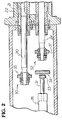
- drive rods and racks There is a substantially different configuration of drive rods and racks as will be further explained below with reference to Figure 2.
- upper and lower shear assemblies 15 and 17, respectively are reciprocably moveable.
- the upper shear assembly 15 has a tubular portion 16 which slides on a guide rail 13 seen in phantom, shear assembly 15 also slides on guide rail 14.
- Lower shear assembly 17 has a tubular portion 18 (only partially visible in Figure 1) which slides on a guide rail not visible in this view, and lower shear assembly 17 also slides on guide rail 14.
- the tubular portion 16 of upper shear assembly 15 has a flange portion or arm 35 which links the shear assembly to a drive rod 20 which is driven from servomotor 28 as explained below with reference to Figure 2.
- the tubular portion 18 of lower shear assembly 17 also has a double flange portion, comprising opposing arms 37, 38. Arm 37 is linked to a drive rod 24 driven by servomotor 28, while arm 38 is aligned with but not linked to a piston rod 31 from air cylinder 26, as further explained below.
- the main frame 19 of shear mechanism 10 is an integrally formed structure, which has advantages noted below. It should be noted that the guide rails 13 and 14 and the drive rods 20, 24 ideally are parallel to each other.
- the drive structures of the shear assembly 10 include a pair of upper and lower rack rods 20 and 24 with respective rack portions the upper one of which is seen at 21.
- the rack portions are geared to a pinion gear within housing 22, such pinion gear being directly coupled to the shaft of the servo motor 28 to be rotated thereby.
- the rack rods 20 and 24 are respectively coupled to the arms 35 and 37 by adaptable joints 30 and 32 in accordance with the present invention, the detailed design of which will be discussed below.
- adaptable joints 30 and 32 permit a certain amount of radial repositioning of the arms 35 and 37 relative to the axes of rods 20 and 24, and additionally a lesser degree of axial displacement and axial skew.
- the piston rod 31 extending from air cylinder 26 has at its end nearest arm 38 a bumper 33.
- Air cylinder 26 is actuated in the event of an electrical malfunction of the shear mechanism 10 to drive the bumper 33 against the arm 38 and thereby move the lower shear assembly 17 out from its central, shearing position.
- adaptable joints such as those shown at 30 and 32 in Figure 2 are incorporated in a pneumatically driven shear mechanism such as that shown in commonly assigned U.S. Patent No. 4,215,611.
- the drive source is an air cylinder-piston assembly rather than a servo-motor
- the piston rod-arm linkage is an adjustable joint rather than a fixed joint.
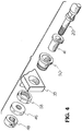
- Rack rod 20 has a hardened circumferential sleeve 41 fitted near the end of the rod, and includes a threaded portion 20t at the rod end.
- Hardened sleeve 41 includes an annular member in the form of a flange portion 43 at its inner end, and a second annular member is provided by a rod nut 46 threaded onto rod end 20T at the other end of sleeve 41.
- a radial surface 44 of sleeve flange 43 and radial surface 47 of rod nut 46 define between them a circumferential region 42 around the hardened sleeve 41.
- Split collar 48 retains rod nut 46 at the end of the rack rod 20.
- Region 42 contains bushing 50, bushing nut 58, and arm 35, which form an integral structure wherein the bushing 50 is secured within a cylindrical aperture of arm 35 by bushing nut 58, which is threaded onto a threaded surface 50t of bushing 50.
- the outer diameter of the body of sleeve 41 is less than the inner diameter of bushing 50 to provide a radial clearance region 70 between these structures.
- a gap on the order of 0.25 -2.5mm is provided between these structures.
- the axial length of bushing 50 is about 0.025 - 0.075 mm less than the separation of radial surfaces 44 and 47, so as to provide an axial clearance region 80. The effect of this is to permit radial repositioning of the arm 35 relative to the drive rod 20, and to a lesser extent, to permit relative axial displacement or axial skew of arm 35 relative to rod 20.
- joints 30 and 32 permit radial repositioning and axial reorientation of arms 35 and 37 relative to drive rods 20 and 24, and thereby prevent premature wear of the moving parts of shear mechanism 10 due to side loading from non-parallelism of the guide rails to the drive rods. Furthermore, by permitting a radial repositioning of the shear assemblies 15 and 17 and their interconnected structures relative to the drive rods 20 and 24, the shear mechanism 10 is able to adapt to variations within dimensional tolerances of the various structures of the shear mechanism drive.
- Figure 5 shows in section an alternative design of a flexible joint 30' generally similar to the joint 30 shown in Figure 3, with the difference that in lieu of a separate bushing 50 and bushing nut 58 secured to arm 35, the arm 35' of Figure 5 includes a cylindrical rim 60 having similar dimensions to those of bushing 50. That is, the length of rim 60 between its end surfaces 53, 54 and its inner diameter at surface 61 is comparable to the length and inner diameter of bushing 50.
- circumferential sleeve 41 may be integral with the drive rod 20.
Landscapes
- Chemical & Material Sciences (AREA)
- Engineering & Computer Science (AREA)
- Materials Engineering (AREA)
- Organic Chemistry (AREA)
- Transmission Devices (AREA)
- Shearing Machines (AREA)
Claims (3)
- Hin- und Herbewegemechanismus (10) einer Glaswarenherstellungsmaschine des Typs, der einen Arm (35) enthält, der an hin- und herbewegenden Teilen (17) gesichert ist, zumindest eine gleitend montierte Antriebsstange (20) mit einer Achse, die im wesentlichen parallel zu der Achse der Hin- und Herbewegung der Teile (17) ist, wobei die Antriebsstange (20) mit dem Arm (35) verbunden ist, so daß der Arm (35) und die Teile (17) sich parallel zu der Antriebsstange (20) bewegen, und eine Antriebseinrichtung (28, 22, 21) zum Hin- und Herbewegen der Antriebsstange entlang ihrer Achse, dadurch gekennzeichnet, daß die Verbindung (32) zwischen dem Arm (35) und der Antriebsstange (20) umfaßt:
ein Umfangselement (41), das an oder einstückig mit der Antriebsstange (20) angebracht ist,
ein erstes (43) und ein zweites (46) ringförmiges Element, die von dem Umfangselement (41) vorstehen, wobei die ringförmigen Elemente radiale Oberflächen (44, 47) haben, die sich gegenüberstehen, und
ein Laufbuchsenelement (50), das an oder einstückig mit dem Arm (35) gesichert ist und um die Antriebsstange (20) zwischen den radialen Oberflächen (44, 47) der ringförmigen Elemente (43, 46) angeordnet ist, und zwar mit einem radialen freien Bereich (70) zwischen dem Umfangselement (41) und dem Laufbuchsenelement (50) und einem axialen freien Bereich (80) zwischen dem Laufbuchsenelement (50) und den radialen Oberflächen (44, 47), um ein eingeschränktes Wiederpositionieren und eine Ausrichtung des Arms (35) relativ zu der Antriebsstange (20) zuzulassen. - Hin- und Herbewegungsmechanismus nach Anspruch 1, wobei die Antriebsstange (20), das erste (43) und das zweite (46) ringförmige Element und das Laufbuchsenelement (50) im radialen Querschnitt kreisförmig sind.
- Hin- und Herbewegungsmechanismus nach Anspruch 1, wobei das Umfangselement (41) eine harte Laufbuchse (41) an der Antriebsstange (20) umfaßt, wobei die Laufbuchse einen Flansch (43) aufweist, der das erste ringförmige Element schafft.
Applications Claiming Priority (2)
| Application Number | Priority Date | Filing Date | Title |
|---|---|---|---|
| US07/134,277 US4781746A (en) | 1987-12-17 | 1987-12-17 | Drive apparatus for straight line shear mechanism |
| US134277 | 1987-12-17 |
Publications (3)
| Publication Number | Publication Date |
|---|---|
| EP0321101A2 EP0321101A2 (de) | 1989-06-21 |
| EP0321101A3 EP0321101A3 (en) | 1990-09-12 |
| EP0321101B1 true EP0321101B1 (de) | 1993-04-07 |
Family
ID=22462608
Family Applications (1)
| Application Number | Title | Priority Date | Filing Date |
|---|---|---|---|
| EP88311012A Expired - Lifetime EP0321101B1 (de) | 1987-12-17 | 1988-11-22 | Hin- und her bewegendes Mechanismus für einen Schermechanismus in gerader Linie |
Country Status (7)
| Country | Link |
|---|---|
| US (1) | US4781746A (de) |
| EP (1) | EP0321101B1 (de) |
| JP (1) | JPH01197332A (de) |
| CN (1) | CN1014983B (de) |
| BR (1) | BR8806322A (de) |
| DE (1) | DE3880108T2 (de) |
| MX (1) | MX163171B (de) |
Families Citing this family (4)
| Publication number | Priority date | Publication date | Assignee | Title |
|---|---|---|---|---|
| US4781746A (en) * | 1987-12-17 | 1988-11-01 | Emhart Industries, Inc. | Drive apparatus for straight line shear mechanism |
| US4859227A (en) * | 1989-01-27 | 1989-08-22 | Emhart Industries, Inc. | Straight line shear mechanism |
| US4869746A (en) * | 1989-02-27 | 1989-09-26 | Emhart Industries, Inc. | Straight line shear mechanism |
| JP3796794B2 (ja) * | 1996-02-21 | 2006-07-12 | 旭硝子株式会社 | 溶融ガラス切断装置 |
Family Cites Families (9)
| Publication number | Priority date | Publication date | Assignee | Title |
|---|---|---|---|---|
| US3996037A (en) * | 1974-02-08 | 1976-12-07 | Emhart Industries, Inc. | Pass through shears for molten glass feeder |
| US4174647A (en) * | 1978-02-08 | 1979-11-20 | Emhart Industries, Inc. | Apparatus for straight line shearing |
| US4215611A (en) * | 1979-02-21 | 1980-08-05 | Emhart Industries, Inc. | Apparatus for straight line shearing |
| US4214494A (en) * | 1979-02-21 | 1980-07-29 | Emhart Industries, Inc. | Apparatus for straight line shearing |
| US4450741A (en) * | 1982-07-14 | 1984-05-29 | Owens-Illinois, Inc. | Multiple gob shearing mechanism operating in a straight line |
| US4500334A (en) * | 1983-08-02 | 1985-02-19 | Maul Technology Corporation | Glass stream cutting apparatus |
| GB8412249D0 (en) * | 1984-05-14 | 1984-06-20 | Bhf Eng Ltd | Straight-line shearing |
| US4699643A (en) * | 1985-05-07 | 1987-10-13 | Emhart Industries, Inc. | Straight line shear |
| US4781746A (en) * | 1987-12-17 | 1988-11-01 | Emhart Industries, Inc. | Drive apparatus for straight line shear mechanism |
-
1987
- 1987-12-17 US US07/134,277 patent/US4781746A/en not_active Expired - Fee Related
-
1988
- 1988-11-22 DE DE8888311012T patent/DE3880108T2/de not_active Expired - Fee Related
- 1988-11-22 EP EP88311012A patent/EP0321101B1/de not_active Expired - Lifetime
- 1988-11-28 BR BR888806322A patent/BR8806322A/pt unknown
- 1988-12-15 MX MX14211A patent/MX163171B/es unknown
- 1988-12-16 JP JP63318346A patent/JPH01197332A/ja active Pending
- 1988-12-16 CN CN88108663.0A patent/CN1014983B/zh not_active Expired
Also Published As
| Publication number | Publication date |
|---|---|
| DE3880108D1 (de) | 1993-05-13 |
| BR8806322A (pt) | 1989-08-15 |
| EP0321101A3 (en) | 1990-09-12 |
| US4781746A (en) | 1988-11-01 |
| DE3880108T2 (de) | 1993-07-15 |
| MX163171B (es) | 1991-09-30 |
| JPH01197332A (ja) | 1989-08-09 |
| CN1033613A (zh) | 1989-07-05 |
| EP0321101A2 (de) | 1989-06-21 |
| CN1014983B (zh) | 1991-12-04 |
Similar Documents
| Publication | Publication Date | Title |
|---|---|---|
| US4669325A (en) | Telescopic assembly | |
| US7600718B2 (en) | Pivoted flap mechanism for adjusting an aerodynamic pivoted flap associated with a wing | |
| US5477744A (en) | Position adustable steering column assembly for a motor vehicle | |
| EP0205939B1 (de) | Antriebs- und Führungsvorrichtung für eine an einem Flugzeugtragflügel angeordnete Klappe | |
| JPH069971B2 (ja) | ラツク・ピニオン式パワ−・ステアリング装置 | |
| EP0321101B1 (de) | Hin- und her bewegendes Mechanismus für einen Schermechanismus in gerader Linie | |
| CN215154987U (zh) | 用于线控转向系统的主轴传动装置和线控转向系统 | |
| DE19901300C1 (de) | Lenksystem | |
| KR102116864B1 (ko) | 차량 액슬 제작용 지그 장치 | |
| DE4336286C1 (de) | Zahnstangenlenkung für Kraftfahrzeuge | |
| EP2422906B1 (de) | Werkzeughalter mit Ausweichmechanismus sowie Verfahren zu dessen Herstellung | |
| EP0277649B1 (de) | Radaufhängung für lenkbare Hinterräder von mit Vorderradlenkung ausgestatteten Kraftfahrzeugen, insbesondere Personenkraftwagen | |
| US6543568B2 (en) | Dual variable-tooth rack and single pinion steering system | |
| NZ510924A (en) | Right hand drive steering system and conversion method from left hand drive vehicle | |
| US11591004B2 (en) | Bracket and steering apparatus | |
| US3994362A (en) | Hydraulically operated steer axle linkage | |
| JP5988392B2 (ja) | ツール駆動装置 | |
| EP3299258B1 (de) | Steer-by-wire lenkung | |
| JPH0625082U (ja) | 4輪操舵車両の後輪操舵装置 | |
| DE1108094B (de) | Mit hydraulischer Hilfskraftbetaetigung arbeitende Lenkeinrichtung fuer Kraftfahrzeuge | |
| JP5125032B2 (ja) | 電動位置調整式ステアリング装置 | |
| CN223327577U (zh) | 用于机动车辆的转向柱 | |
| DE19637997C1 (de) | Zahnstangenlenkung für ein Kraftfahrzeug mit einer Starrachse | |
| DE10033305C2 (de) | Verfahren zur Herstellung von Zahnstangenlenkgehäusen | |
| DE102024002178A1 (de) | Lenkeinrichtung für ein Kraftfahrzeug und Kraftfahrzeug |
Legal Events
| Date | Code | Title | Description |
|---|---|---|---|
| PUAI | Public reference made under article 153(3) epc to a published international application that has entered the european phase |
Free format text: ORIGINAL CODE: 0009012 |
|
| AK | Designated contracting states |
Kind code of ref document: A2 Designated state(s): DE FR GB IT |
|
| RAP1 | Party data changed (applicant data changed or rights of an application transferred) |
Owner name: EMHART INDUSTRIES, INC. |
|
| PUAL | Search report despatched |
Free format text: ORIGINAL CODE: 0009013 |
|
| AK | Designated contracting states |
Kind code of ref document: A3 Designated state(s): DE FR GB IT |
|
| 17P | Request for examination filed |
Effective date: 19901012 |
|
| RAP1 | Party data changed (applicant data changed or rights of an application transferred) |
Owner name: EMHART GLASS MACHINERY INC., |
|
| RAP1 | Party data changed (applicant data changed or rights of an application transferred) |
Owner name: EMHART GLASS MACHINERY INVESTMENTS INC. |
|
| 17Q | First examination report despatched |
Effective date: 19920114 |
|
| GRAA | (expected) grant |
Free format text: ORIGINAL CODE: 0009210 |
|
| AK | Designated contracting states |
Kind code of ref document: B1 Designated state(s): DE FR GB IT |
|
| REF | Corresponds to: |
Ref document number: 3880108 Country of ref document: DE Date of ref document: 19930513 |
|
| ET | Fr: translation filed | ||
| ITF | It: translation for a ep patent filed | ||
| PLBE | No opposition filed within time limit |
Free format text: ORIGINAL CODE: 0009261 |
|
| STAA | Information on the status of an ep patent application or granted ep patent |
Free format text: STATUS: NO OPPOSITION FILED WITHIN TIME LIMIT |
|
| 26N | No opposition filed | ||
| PGFP | Annual fee paid to national office [announced via postgrant information from national office to epo] |
Ref country code: FR Payment date: 19951013 Year of fee payment: 8 |
|
| PGFP | Annual fee paid to national office [announced via postgrant information from national office to epo] |
Ref country code: GB Payment date: 19951020 Year of fee payment: 8 |
|
| PGFP | Annual fee paid to national office [announced via postgrant information from national office to epo] |
Ref country code: DE Payment date: 19951027 Year of fee payment: 8 |
|
| PG25 | Lapsed in a contracting state [announced via postgrant information from national office to epo] |
Ref country code: GB Effective date: 19961122 |
|
| GBPC | Gb: european patent ceased through non-payment of renewal fee |
Effective date: 19961122 |
|
| PG25 | Lapsed in a contracting state [announced via postgrant information from national office to epo] |
Ref country code: FR Effective date: 19970731 |
|
| PG25 | Lapsed in a contracting state [announced via postgrant information from national office to epo] |
Ref country code: DE Effective date: 19970801 |
|
| REG | Reference to a national code |
Ref country code: FR Ref legal event code: ST |
|
| PG25 | Lapsed in a contracting state [announced via postgrant information from national office to epo] |
Ref country code: IT Free format text: LAPSE BECAUSE OF NON-PAYMENT OF DUE FEES;WARNING: LAPSES OF ITALIAN PATENTS WITH EFFECTIVE DATE BEFORE 2007 MAY HAVE OCCURRED AT ANY TIME BEFORE 2007. THE CORRECT EFFECTIVE DATE MAY BE DIFFERENT FROM THE ONE RECORDED. Effective date: 20051122 |