EP0321195A2 - Oszilierende Maschine - Google Patents
Oszilierende Maschine Download PDFInfo
- Publication number
- EP0321195A2 EP0321195A2 EP88311806A EP88311806A EP0321195A2 EP 0321195 A2 EP0321195 A2 EP 0321195A2 EP 88311806 A EP88311806 A EP 88311806A EP 88311806 A EP88311806 A EP 88311806A EP 0321195 A2 EP0321195 A2 EP 0321195A2
- Authority
- EP
- European Patent Office
- Prior art keywords
- base
- support base
- motor
- linear motion
- ring mold
- Prior art date
- Legal status (The legal status is an assumption and is not a legal conclusion. Google has not performed a legal analysis and makes no representation as to the accuracy of the status listed.)
- Granted
Links
Images

Classifications
-
- C—CHEMISTRY; METALLURGY
- C03—GLASS; MINERAL OR SLAG WOOL
- C03B—MANUFACTURE, SHAPING, OR SUPPLEMENTARY PROCESSES
- C03B32/00—Thermal after-treatment of glass products not provided for in groups C03B19/00, C03B25/00 - C03B31/00 or C03B37/00, e.g. crystallisation, eliminating gas inclusions or other impurities; Hot-pressing vitrified, non-porous, shaped glass products
-
- C—CHEMISTRY; METALLURGY
- C03—GLASS; MINERAL OR SLAG WOOL
- C03B—MANUFACTURE, SHAPING, OR SUPPLEMENTARY PROCESSES
- C03B27/00—Tempering or quenching glass products
- C03B27/04—Tempering or quenching glass products using gas
- C03B27/044—Tempering or quenching glass products using gas for flat or bent glass sheets being in a horizontal position
- C03B27/0442—Tempering or quenching glass products using gas for flat or bent glass sheets being in a horizontal position for bent glass sheets
-
- C—CHEMISTRY; METALLURGY
- C03—GLASS; MINERAL OR SLAG WOOL
- C03B—MANUFACTURE, SHAPING, OR SUPPLEMENTARY PROCESSES
- C03B23/00—Re-forming shaped glass
- C03B23/02—Re-forming glass sheets
-
- C—CHEMISTRY; METALLURGY
- C03—GLASS; MINERAL OR SLAG WOOL
- C03B—MANUFACTURE, SHAPING, OR SUPPLEMENTARY PROCESSES
- C03B23/00—Re-forming shaped glass
- C03B23/02—Re-forming glass sheets
- C03B23/023—Re-forming glass sheets by bending
- C03B23/03—Re-forming glass sheets by bending by press-bending between shaping moulds
-
- C—CHEMISTRY; METALLURGY
- C03—GLASS; MINERAL OR SLAG WOOL
- C03B—MANUFACTURE, SHAPING, OR SUPPLEMENTARY PROCESSES
- C03B27/00—Tempering or quenching glass products
- C03B27/04—Tempering or quenching glass products using gas
Definitions
- the present invention relates to an oscillating device for oscillating a ring mold which supports the peripheral edges of a sheet glass in a circular or similar motion within a horizontal plane.
- the peripheral edges of the sheet glass which is heated to a high temperature is supported, from below, by a ring mold, and oscillatory motion is imparted to the ring mold to move the same in a circular, elliptical, or linear path within a horizontal plane while cooling air is being applied to the surface of the sheet glass.
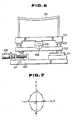
- FIG. 6 of the accompanying drawings shows a conventional oscillating device for imparting such oscillatory motion to a sheet glass.
- the illustrated oscillating device has a first support plate 104 movably disposed on a base 100 through a slide bearing 101 for movement in the direction of an X-axis (i.e., a horizontal direction in FIG. 6), and a second support plate 104 movably disposed on the first support plate 102 through slide bearings 103 for movement in the direction of a Y-axis (i.e., a direction normal to the sheet of FIG. 6).
- a ring mold 105 is supported on the second support plate 104.
- the first support plate 102 is moved in the X-axis direction by a motor 106 through a ball screw 107
- the second support plate 104 is moved in the Y-axis direction by a motor 108 through a ball screw 109.
- the ring mold 105 may be oscillated in an elliptical path which, as shown in FIG. 7, starts from an origin o to a to b to c to d to a to o . Between the points o and a , only the motor 106 is energized to move the ring mold 105.
- the ring mold supports the peripheral edges of a sheet glass thereon. If the ring mold failed to return to the original position, the supported sheet glass would be displaced out of a desired position. Therefore, the oscillating device is arranged such that it will finally move the ring mold back to the origin o at the end of an oscillating cycle.
- the conventional oscillating device tends to fail to move the ring mold 105 along an exact path and also to return the ring mold 105 back to the origin because of a backlash between the threads of the ball screw 107 and a nut threaded thereover, different weights of the two systems movable along the X- and Y-axes, and a failure to accurately control the timing to start the two motors 106, 108.
- an oscillating device for oscillating an object, comprising a base, a single motor mounted on the base, a support base mounted on the base for supporting an object, the support base being movable in first and second orthogonal horizontal directions, a first converter mechanism mounted on the base and coupled to the support base for converting rotation from the motor into a first linear motion in the first horizontal direction and applying the first linear motion to the support base, a second converter mechanism mounted on the base and coupled to the support base for converting rotation from the motor into a second linear motion in the second horizontal direction and applying the second linear motion to the support base, and a clutch mechanism mounted on the base and having two clutch plates with respective engaging surfaces thereof angularly displaced from each other for selectively transmitting the rotation from the motor to the second converter mechanism.
- the rotation of the motor is transmitted via a gearbox to the first converter mechanism, by which the rotation is transmitted as the first linear motion to the support base.
- the clutch mechanism is engaged to enable the second converter mechanism to impart the second linear motion to the support base in the second horizontal direction. Therefore, the support base makes a combined two-dimensional motion based on the first and second linear motions.
- an oscillating device according to the present invention is disposed on a table 1 of a mold changer carriage, for example.
- the table 1 supports thereon a plurality of upstanding posts 2.
- a support base 4 is movably supported on the upper ends of the support posts 2 by means of slide bearings 3 for movement in the direction of an X-axis (i.e., a horizontal direction in FIG. 1) and in the direction of a Y-axis (i.e., a direction normal to the sheet of FIG. 1).
- a ring mold outer frame 6 is fixedly mounted on the support base 4 by clamps 6, with a ring mold 7 disposed on the ring mold outer frame 6.
- An upper mold member 8 is positioned above the ring mold 7, and a lower mold member 9 is positioned below the ring mold 7.
- Each of the upper and lower mold members 8, 9 is of a hollow structure, and has a plurality of small holes defined in its shaping surface for ejecting cooling air toward a sheet glass G which is supported on the ring mold 7 after the sheet glass G has been shaped.
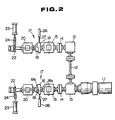
- a power transmitting mechanism 10 is mounted on the table 1. As shown in FIGS. 1 and 2, the power transmitting mechanism 10 includes a pair of gearboxes 13 interconnected by a connecting rod 12. Rotation of a variable-speed motor 11 equipped with a speed reducer is transmitted to the gearboxes 13, from which the rotation is transmitted through couplings 14 to two respective gearboxes 15. The rotation is then transmitted from the gearboxes 15 to first converter mechanisms 16 and respective clutch plates 18 of two clutch mechanisms 17.
- the clutch mechanisms 17 also include other clutch plates 19 associated respectively with the clutch plates 18 and mounted on one ends of shafts extending from two respective gearboxes 20, through which the rotation from the clutch mechanisms 17 is transmitted respective second converter mechanisms 21.
- Two pinions 22 with one-way clutches are fixed respectively to the other ends of the shafts of the gearboxes 20, and are held in mesh with respective racks 24 which are reciprocally movable by respective cylinder units 23.
- the cylinder units 23 are operated to angularly space engaging surfaces 19a of the clutch plates 19 from engaging surfaces 18a of the clutch plates 18 by 90°.
- the clutch plates 18 have holes 25 defined in outer circumferential surfaces thereof. The clutch plates 18 can be stopped in constant angular positions by inserting pins 27 moved by respective cylinder units 26 into the respective holes 25.
- the first and second converter mechanisms 16, 21 will be described below.
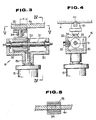
- the first and second converter mechanisms 16, 21 are structurally identical to each other, but angularly displaced 90° from each other. Only the first converter mechanisms 16 will be described below with reference to FIGS. 3 through 5.
- Each of the first converter mechanisms 16 has an upwardly open elongate box 30 mounted on the upper end of a rotatable shaft 15a projecting upwardly from the gearbox 15.
- a ball screw 31 is longitudinally disposed in the box 30 and extends through a hole defined in an eccentric block 32.
- the ball screw 31 is threaded through a nut 33 fixed to the eccentric block 32. By manually rotating the ball screw 31 about its own axis, the eccentric block 32 can be moved over the ball screw 31 along longitudinal inner surfaces of the box 30.
- An upstanding pin 34 is mounted on an upper surface of the eccentric block 32.
- a bifurcated slide 35 is fitted over an upper portion of the pin 34 and slidably engages a rail 4a attached to a lower surface of the support base 4.
- the eccentric block 32 is fixed to the box 30 by means of a screw 36 threaded through a side wall of the box 30 into the eccentric block 32.
- the support base 4 therefore makes a composite motion based on the linear motions transmitted from the respective first and second converter mechanisms 16, 21.
- the ring mold 7 supported on the support base 4 is reciprocally moved along a circular, elliptical, or linear path.
- the motor 11 is energized to move the ring mold 7 only along the X-axis from an origin o to a point a through the gearboxes 13, 15 and the first converter mechanisms 16. During this time, the ring mold 7 does not move in the Y-axis direction. Thereafter, when the clutch plates 18 are turned 90°, the clutch plates 18, 19 engage each other to transmit the rotation of the motor 11 also to the second converter mechanisms 21. The ring mold 7 is then caused to move in the Y-axis direction, so that the ring mold 7 repeats a composite circular motion based on the motions in the X- and Y-axis directions.
- the motor 11 is de-energized, and the cylinder units 26 are actuated to insert the pins 27 into the respective holes 25 in the clutch plates 18.
- the ring mold 7 is positioned at a point d .
- the cylinder units 23 are actuated to operate the racks 24 and the pinions 22 to angularly return the clutch plates 19 by 90° so as to be angularly spaced 90° from the clutch plates 18. This movement of the clutch plates 19 returns the ring mold 7 from the point d to the origin o in readiness for a next oscillating cycle.
- any of various members or objects which support a portion of a sheet glass may be oscillated by the oscillating device of the present invention.
- the support base 4 and hence the ring mold 7 thereon are moved in a combined motion in two horizontal directions, i.e., two-dimensionally, by the single motor 11. Therefore, the ring mold 7 can follow a more accurate path than would if a plurality of motors were employed to move the ring mold. Since the motor 11 is rotated in one direction only, no substantial backlashes will be developed quickly in the various mechanisms of the oscillating device. Moreover, the ring mold 7 can accurately be moved back to its origin by the angularly displaceable clutch mechanisms 18, 19.
Landscapes
- Chemical & Material Sciences (AREA)
- Engineering & Computer Science (AREA)
- Materials Engineering (AREA)
- Organic Chemistry (AREA)
- Physics & Mathematics (AREA)
- Thermal Sciences (AREA)
- Transmission Devices (AREA)
- Re-Forming, After-Treatment, Cutting And Transporting Of Glass Products (AREA)
- Forging (AREA)
- Apparatuses For Generation Of Mechanical Vibrations (AREA)
Applications Claiming Priority (2)
| Application Number | Priority Date | Filing Date | Title |
|---|---|---|---|
| JP1987192543U JPH0426420Y2 (de) | 1987-12-18 | 1987-12-18 | |
| JP192543/87U | 1987-12-18 |
Publications (3)
| Publication Number | Publication Date |
|---|---|
| EP0321195A2 true EP0321195A2 (de) | 1989-06-21 |
| EP0321195A3 EP0321195A3 (en) | 1990-09-12 |
| EP0321195B1 EP0321195B1 (de) | 1993-04-14 |
Family
ID=16293027
Family Applications (1)
| Application Number | Title | Priority Date | Filing Date |
|---|---|---|---|
| EP88311806A Expired - Lifetime EP0321195B1 (de) | 1987-12-18 | 1988-12-14 | Oszilierende Maschine |
Country Status (5)
| Country | Link |
|---|---|
| US (1) | US4906905A (de) |
| EP (1) | EP0321195B1 (de) |
| JP (1) | JPH0426420Y2 (de) |
| KR (1) | KR920000667B1 (de) |
| DE (1) | DE3880285T2 (de) |
Cited By (1)
| Publication number | Priority date | Publication date | Assignee | Title |
|---|---|---|---|---|
| EP0581742A1 (de) * | 1992-07-31 | 1994-02-02 | POPPI S.p.A. | Tempervorrichtung, insbesondere für Glasscheiben und ähnlichen |
Families Citing this family (2)
| Publication number | Priority date | Publication date | Assignee | Title |
|---|---|---|---|---|
| US6057662A (en) * | 1998-02-25 | 2000-05-02 | Applied Materials, Inc. | Single motor control for substrate handler in processing system |
| US11485667B2 (en) * | 2019-01-25 | 2022-11-01 | Corning Incorporated | Dual-elevation edge roll system for fused downdraw glass forming |
Family Cites Families (7)
| Publication number | Priority date | Publication date | Assignee | Title |
|---|---|---|---|---|
| US3454388A (en) * | 1965-06-28 | 1969-07-08 | Libbey Owens Ford Glass Co | Oscillatory spray tempering apparatus |
| US3488178A (en) * | 1966-04-18 | 1970-01-06 | Libbey Owens Ford Co | Apparatus for reshaping and cooling glass sheets |
| US3510286A (en) * | 1966-08-12 | 1970-05-05 | Ppg Industries Inc | Method and apparatus for bending and tempering glass sheets |
| US3849100A (en) * | 1972-10-24 | 1974-11-19 | Ppg Industries Inc | Tempering glass sheets |
| US3905794A (en) * | 1974-10-17 | 1975-09-16 | Libbey Owens Ford Co | Glass sheet supporting, shaping and conveying apparatus |
| US3994711A (en) * | 1975-09-15 | 1976-11-30 | Mcmaster Harold | Glass tempering system including oscillating roller furnace |
| JPS6183640A (ja) * | 1984-09-26 | 1986-04-28 | Nippon Sheet Glass Co Ltd | 板ガラスのプレス成形方法及び装置 |
-
1987
- 1987-12-18 JP JP1987192543U patent/JPH0426420Y2/ja not_active Expired
-
1988
- 1988-12-14 EP EP88311806A patent/EP0321195B1/de not_active Expired - Lifetime
- 1988-12-14 DE DE8888311806T patent/DE3880285T2/de not_active Expired - Fee Related
- 1988-12-15 KR KR1019880016700A patent/KR920000667B1/ko not_active Expired
- 1988-12-16 US US07/285,863 patent/US4906905A/en not_active Expired - Fee Related
Cited By (1)
| Publication number | Priority date | Publication date | Assignee | Title |
|---|---|---|---|---|
| EP0581742A1 (de) * | 1992-07-31 | 1994-02-02 | POPPI S.p.A. | Tempervorrichtung, insbesondere für Glasscheiben und ähnlichen |
Also Published As
| Publication number | Publication date |
|---|---|
| KR920000667B1 (ko) | 1992-01-20 |
| KR890009782A (ko) | 1989-08-04 |
| DE3880285D1 (de) | 1993-05-19 |
| DE3880285T2 (de) | 1993-07-29 |
| JPH0198134U (de) | 1989-06-30 |
| US4906905A (en) | 1990-03-06 |
| EP0321195B1 (de) | 1993-04-14 |
| EP0321195A3 (en) | 1990-09-12 |
| JPH0426420Y2 (de) | 1992-06-25 |
Similar Documents
| Publication | Publication Date | Title |
|---|---|---|
| US3703834A (en) | Device for transmitting control translatory movements | |
| KR0151439B1 (ko) | 파이프 벤딩 방법 및 그 장치 | |
| CN113319563B (zh) | 基于管片式散热器的自动上料穿管机构 | |
| EP0435417A1 (de) | Werkstücktransporteinrichtung | |
| US4989717A (en) | Pallet exchanging apparatus for machine tool | |
| US4906905A (en) | Device for oscillating a ring mold for sheet glass | |
| CN110786884A (zh) | 一种超声耦合剂自动涂抹装置 | |
| CA1316370C (en) | Device for oscillating a ring mold for sheet glass | |
| CN110102693A (zh) | 离合器从动盘辅助自动铆钉设备 | |
| CN207076877U (zh) | 一种板料对中装置 | |
| CN113172405A (zh) | 多压头自动切换式压装设备 | |
| KR970006926Y1 (ko) | 음극선관의 화면특성 측정 수단의 이송장치 | |
| KR900003674B1 (ko) | 중기 발생기 튜브 시이트 자동 스탬핑 장치 | |
| JP2000320985A (ja) | チューブ拡管装置及びチューブ位置検出方法 | |
| CN110538933B (zh) | 一种胀管机接收座高度规格切换机构 | |
| CN115055959B (zh) | 一种脱水塔冷凝器用管芯组件装配设备 | |
| US4580942A (en) | Device for the manipulation of workpieces, assembly parts, or the like | |
| JPH06510516A (ja) | 溶融ガラスの単数または複数のストランドを個々のゴブに分離するための装置 | |
| CN120920980B (zh) | 一种电力变压器铁芯焊接设备 | |
| SU941003A1 (ru) | Установка дл безударной клепки стержневых заклепок | |
| CN219854368U (zh) | 一种转动压装机构 | |
| CN223012402U (zh) | 一种自动上料的组装铆接设备 | |
| CN220839006U (zh) | 一种板件加工侧向定位机构 | |
| JPH022505Y2 (de) | ||
| CN209536399U (zh) | 移动夹手装置 |
Legal Events
| Date | Code | Title | Description |
|---|---|---|---|
| PUAI | Public reference made under article 153(3) epc to a published international application that has entered the european phase |
Free format text: ORIGINAL CODE: 0009012 |
|
| AK | Designated contracting states |
Kind code of ref document: A2 Designated state(s): DE FR GB IT |
|
| 17P | Request for examination filed |
Effective date: 19891219 |
|
| PUAL | Search report despatched |
Free format text: ORIGINAL CODE: 0009013 |
|
| AK | Designated contracting states |
Kind code of ref document: A3 Designated state(s): DE FR GB IT |
|
| 17Q | First examination report despatched |
Effective date: 19920211 |
|
| GRAA | (expected) grant |
Free format text: ORIGINAL CODE: 0009210 |
|
| AK | Designated contracting states |
Kind code of ref document: B1 Designated state(s): DE FR GB IT |
|
| ET | Fr: translation filed | ||
| REF | Corresponds to: |
Ref document number: 3880285 Country of ref document: DE Date of ref document: 19930519 |
|
| ITF | It: translation for a ep patent filed | ||
| PGFP | Annual fee paid to national office [announced via postgrant information from national office to epo] |
Ref country code: GB Payment date: 19931206 Year of fee payment: 6 |
|
| PGFP | Annual fee paid to national office [announced via postgrant information from national office to epo] |
Ref country code: DE Payment date: 19931208 Year of fee payment: 6 |
|
| PGFP | Annual fee paid to national office [announced via postgrant information from national office to epo] |
Ref country code: FR Payment date: 19931209 Year of fee payment: 6 |
|
| PLBE | No opposition filed within time limit |
Free format text: ORIGINAL CODE: 0009261 |
|
| STAA | Information on the status of an ep patent application or granted ep patent |
Free format text: STATUS: NO OPPOSITION FILED WITHIN TIME LIMIT |
|
| 26N | No opposition filed | ||
| PG25 | Lapsed in a contracting state [announced via postgrant information from national office to epo] |
Ref country code: GB Effective date: 19941214 |
|
| GBPC | Gb: european patent ceased through non-payment of renewal fee |
Effective date: 19941214 |
|
| PG25 | Lapsed in a contracting state [announced via postgrant information from national office to epo] |
Ref country code: FR Effective date: 19950831 |
|
| PG25 | Lapsed in a contracting state [announced via postgrant information from national office to epo] |
Ref country code: DE Effective date: 19950901 |
|
| REG | Reference to a national code |
Ref country code: FR Ref legal event code: ST |
|
| PG25 | Lapsed in a contracting state [announced via postgrant information from national office to epo] |
Ref country code: IT Free format text: LAPSE BECAUSE OF NON-PAYMENT OF DUE FEES;WARNING: LAPSES OF ITALIAN PATENTS WITH EFFECTIVE DATE BEFORE 2007 MAY HAVE OCCURRED AT ANY TIME BEFORE 2007. THE CORRECT EFFECTIVE DATE MAY BE DIFFERENT FROM THE ONE RECORDED. Effective date: 20051214 |