EP0321222A2 - Telephone - Google Patents
Telephone Download PDFInfo
- Publication number
- EP0321222A2 EP0321222A2 EP88311843A EP88311843A EP0321222A2 EP 0321222 A2 EP0321222 A2 EP 0321222A2 EP 88311843 A EP88311843 A EP 88311843A EP 88311843 A EP88311843 A EP 88311843A EP 0321222 A2 EP0321222 A2 EP 0321222A2
- Authority
- EP
- European Patent Office
- Prior art keywords
- receiver
- telephone
- user
- head
- receivers
- Prior art date
- Legal status (The legal status is an assumption and is not a legal conclusion. Google has not performed a legal analysis and makes no representation as to the accuracy of the status listed.)
- Withdrawn
Links
- 239000003990 capacitor Substances 0.000 claims description 5
- 210000003128 head Anatomy 0.000 description 12
- 230000003247 decreasing effect Effects 0.000 description 1
- 238000000034 method Methods 0.000 description 1
- 238000012986 modification Methods 0.000 description 1
- 230000004048 modification Effects 0.000 description 1
- 210000003454 tympanic membrane Anatomy 0.000 description 1
Images

Classifications
-
- H—ELECTRICITY
- H04—ELECTRIC COMMUNICATION TECHNIQUE
- H04M—TELEPHONIC COMMUNICATION
- H04M1/00—Substation equipment, e.g. for use by subscribers
- H04M1/02—Constructional features of telephone sets
- H04M1/03—Constructional features of telephone transmitters or receivers, e.g. telephone hand-sets
-
- H—ELECTRICITY
- H04—ELECTRIC COMMUNICATION TECHNIQUE
- H04M—TELEPHONIC COMMUNICATION
- H04M1/00—Substation equipment, e.g. for use by subscribers
- H04M1/60—Substation equipment, e.g. for use by subscribers including speech amplifiers
- H04M1/62—Constructional arrangements
Definitions
- the present invention relates to a telephone, in particular, to that wherein received sound from the receivers is positioned in the user's head in order to attain a high intelligibility.
- candlestick phone In “candlestick phone”, a mouthpiece is united with a cradle, and a receiver cord is provided in such manner that it renders a single receiver operable with a degree of freedom.
- candlestick phone has the drawback that the user hears a received sound with one ear because candlestick phone also has only one receiver as desk- and pay-phones.
- Microphone-attached headphones are used in telephone exchange to attain a satisfactorily high intelligibility. The user must cumbersomely put it on the head in order to attain such an intelligibility.
- the present invention provides a telephone which is free of such a drawback and superior in intelligibility.
- An object of the present invention is to equip a second receiver to a telephone having a first receiver in such manner that a received sound from the two receivers is positioned in the user's head.
- the present invention relates to a telephone, characterized in that a second receiver is added to a telephone having only one receiver in such manner that a received sound from the two receivers is positioned in the user's head.
- the sound receiver is located so as to direct sound towards the user's head.
- the second receiver is mounted on a support so that sound may be directed towards the user's head on the opposite side of the head from the first receiver.
- the distance of the second receiver from the user's head and/or the volume of the second receiver is adjustable to balance the sound received from the two receivers so that the sound appears to be located at the centre of the user's head.
- reference numeral (1) designates receiver; (2), speaker; (3), circuitry; (4), capacitor; (5), variable resistor; (6), amplifier; (7), loudspeaker; (8), phone base; (9), pliable supporting member; (10), case; (11), lead; and (12), plug.
- FIG.1 is the circuit of an embodiment according to the invention.
- Reference numerals (1) and (2) designate a receiver and a speaker respectively which are connected with a circuitry (3) provided in a phone base.
- the receiver (1) is connected with an amplifier (6) through a capacitor (4) and a variable resistor (5), while an output terminal of the amplifier (6) is connected with a loudspeaker (7).
- the amplifier (6) substantially does not change the impedance of a telephone circuit when an input terminal of the amplifier (6) is connected with the receiver (1).
- the capacitance of the capacitor (4), the resistance of the variable resistor (5) and the input impedance of the amplifier (6) are set to 0.1 microfarads, 10 kiloohms and 10 kiloohms respectively, the combined resistance thereof becomes about 8 kiloohms.
- the influence on the telephone circuit that may occur when the receiver (1) is connected thereto can be reduced to a negligible level with respect to the impedance of standard telephone circuit, i.e. 600 ohms.
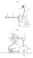
- FIG.2 shows an embodiment wherein a second receiver is provided by enclosing an amplifier (6), a loudspeaker (7) and a variable resistor (5) in a case (10), and wherein the loudspeaker (7) is stationarily attached to the case (10).
- FIG.3 shows another embodiment wherein a second receiver is provided by enclosing an amplifier (6) and a variable resistor (5) in a case (10), and attaching to the case (10) a pliable supporting member (9), such as that of flexible shaft, having a loudspeaker (7) at its end. With this arrangement, the position of the loudspeaker (7) is freely adjustable.
- FIG.4 is illustrative of the method of using the telephone according to the invention.
- the phone base (8) containing a circuitry (3) and a second receiver as shown, for example, in FIG.3 are placed on a desk.
- the receiver (1) is put on the user's ear, and the position of the loudspeaker (7) is then adjusted at the side of the other user's ear.
- the variable resistor (5) is adjusted with respect to the distance between the user's ear and the loudspeaker (7) to a level where a received sound from the receiver (1) and loudspeaker (7) positions in the user's head, preferably, approximately in the center of the user's head.
- the desired output level varies dependently on the sound pressure level of the loudspeaker (7), as well as on the sound pressure that is required on the user's eardrum:
- the ratio of L1:L2 is usually 1:10 to 1:50.
- the output level of the amplifier is usually set to several watts or lower, preferably, 50 to 500 milliwatts.
- variable resistor with a switching means can be used as the variable resistor (5) so that the user can suspend a received sound from the second receiver.
- the phone base (8) and the second receiver can be arranged in such manner that they can be freely disconnected, for example, with a plug (12) provided at the end of a lead (11) as shown in Fig. 3.
- the volume of the second receiver is adjustable independently of the first receiver.
- the first and second receivers of the present invention are not physically connected together as a unit which needs to be worn by the user.
- the present telephone is advantageously usable in telephones in general including pay phones.
Landscapes
- Engineering & Computer Science (AREA)
- Signal Processing (AREA)
- Telephone Set Structure (AREA)
- Mobile Radio Communication Systems (AREA)
Abstract
The intelligibility of a telephone having a first receiver (1) is improved by equipping thereto a second receiver (7) in such manner that sound from the two receivers is positioned in the user's head, preferably, approximately in the center of the user's head. The second receiver is provided by electrically connecting a loudspeaker (7) with the first receiver, if necessary, through an amplifier and a variable resistor (5). Sound received from the two receivers is positioned in the user's head by controlling the distance between the first and second receivers.
Description
- The present invention relates to a telephone, in particular, to that wherein received sound from the receivers is positioned in the user's head in order to attain a high intelligibility.
- Conventional desk- and pay-phones have the drawback that they tend to attain a decreased intelligibility because only one receiver is provided with a speaker and the user hears a received sound with one ear.
- In "candlestick phone", a mouthpiece is united with a cradle, and a receiver cord is provided in such manner that it renders a single receiver operable with a degree of freedom. Candlestick phone, however, has the drawback that the user hears a received sound with one ear because candlestick phone also has only one receiver as desk- and pay-phones.
- Microphone-attached headphones are used in telephone exchange to attain a satisfactorily high intelligibility. The user must cumbersomely put it on the head in order to attain such an intelligibility.
- The present invention provides a telephone which is free of such a drawback and superior in intelligibility.
- An object of the present invention is to equip a second receiver to a telephone having a first receiver in such manner that a received sound from the two receivers is positioned in the user's head.
- More particularly, the present invention relates to a telephone, characterized in that a second receiver is added to a telephone having only one receiver in such manner that a received sound from the two receivers is positioned in the user's head.
- Preferably the sound receiver is located so as to direct sound towards the user's head. Preferably the second receiver is mounted on a support so that sound may be directed towards the user's head on the opposite side of the head from the first receiver. Preferably the distance of the second receiver from the user's head and/or the volume of the second receiver is adjustable to balance the sound received from the two receivers so that the sound appears to be located at the centre of the user's head.
- The present invention will hereinafter be explained with reference to the accompanying drawings, in which:
- FIG.1 is the circuit of an embodiment according to the invention;
- FIGS. 2 and 3 are the perspective views of second receivers according to the invention; and
- FIG. 4 is the front view of an embodiment according to the invention when in use.
- Throughout the drawings, reference numeral (1) designates receiver; (2), speaker; (3), circuitry; (4), capacitor; (5), variable resistor; (6), amplifier; (7), loudspeaker; (8), phone base; (9), pliable supporting member; (10), case; (11), lead; and (12), plug.
- FIG.1 is the circuit of an embodiment according to the invention.
- Reference numerals (1) and (2) designate a receiver and a speaker respectively which are connected with a circuitry (3) provided in a phone base. The receiver (1) is connected with an amplifier (6) through a capacitor (4) and a variable resistor (5), while an output terminal of the amplifier (6) is connected with a loudspeaker (7).
- Desirably, the amplifier (6) substantially does not change the impedance of a telephone circuit when an input terminal of the amplifier (6) is connected with the receiver (1). When the capacitance of the capacitor (4), the resistance of the variable resistor (5) and the input impedance of the amplifier (6) are set to 0.1 microfarads, 10 kiloohms and 10 kiloohms respectively, the combined resistance thereof becomes about 8 kiloohms. Thus, the influence on the telephone circuit that may occur when the receiver (1) is connected thereto can be reduced to a negligible level with respect to the impedance of standard telephone circuit, i.e. 600 ohms.
- FIG.2 shows an embodiment wherein a second receiver is provided by enclosing an amplifier (6), a loudspeaker (7) and a variable resistor (5) in a case (10), and wherein the loudspeaker (7) is stationarily attached to the case (10). FIG.3 shows another embodiment wherein a second receiver is provided by enclosing an amplifier (6) and a variable resistor (5) in a case (10), and attaching to the case (10) a pliable supporting member (9), such as that of flexible shaft, having a loudspeaker (7) at its end. With this arrangement, the position of the loudspeaker (7) is freely adjustable.
- FIG.4 is illustrative of the method of using the telephone according to the invention. Prior to its use, the phone base (8) containing a circuitry (3) and a second receiver as shown, for example, in FIG.3 are placed on a desk. When in use, the receiver (1) is put on the user's ear, and the position of the loudspeaker (7) is then adjusted at the side of the other user's ear. Thereafter, the variable resistor (5) is adjusted with respect to the distance between the user's ear and the loudspeaker (7) to a level where a received sound from the receiver (1) and loudspeaker (7) positions in the user's head, preferably, approximately in the center of the user's head.
- In the case of using an amplifier, its desired output level varies dependently on the sound pressure level of the loudspeaker (7), as well as on the sound pressure that is required on the user's eardrum: Now representing the distance between the receiver (1) and the user's ear and that between the other user's ear and the loudspeaker (7) with symbols "L₁" and "L₂" respectively, the ratio of L₁:L₂ is usually 1:10 to 1:50. Thus, the output level of the amplifier is usually set to several watts or lower, preferably, 50 to 500 milliwatts.
- To connect the phone base (8) with the second receiver, for example, a variable resistor with a switching means can be used as the variable resistor (5) so that the user can suspend a received sound from the second receiver. Furthermore, the phone base (8) and the second receiver can be arranged in such manner that they can be freely disconnected, for example, with a plug (12) provided at the end of a lead (11) as shown in Fig. 3. The volume of the second receiver is adjustable independently of the first receiver.
- It will be seen that unlike headphones, the first and second receivers of the present invention are not physically connected together as a unit which needs to be worn by the user.
- As described above, since in the present invention a second receiver is equipped to a telephone having only one receiver in such manner that a received sound from the receivers positions in the user's head, the telephone can attain a much higher intelligibility than conventional telephone. Thus, the present telephone is advantageously usable in telephones in general including pay phones.
- Having described specific embodiments of my bearing, it is believed obvious that modifications and variations of my invention are possible in light of the above teachings.
Claims (11)
1. In a telephone having a first receiver, the improvement whereby the intelligibility is increased, comprising equipping a second receiver to the telephone in such manner that sound received from the two receivers is positioned in the user's head.
2. A telephone according to claim 1 wherein means is provided to balance the sound received from the two receivers so that the sound received appears to be located at the centre of the user's head.
3. A telephone according to claim 2 in which the second receiver is located on an adjustable support directing sound towards a user's head at a variable distance from the user's head.
4. A telephone according to claim 2 or claim 3 in which the volume emitted by the second receiver is adjustable independently of the first receiver.
5. The telephone of claim 1, wherein the distance between said first and second receivers is variable.
6. The telephone of claim 1, wherein said second receiver is a loudspeaker.
7. The telephone of claim 6, wherein said loudspeaker is connected with the first receiver through a capacitor, a variable resistor, and an amplifier.
8. The telephone of claim 6, wherein said loudspeaker is attached to one end of a pliable supporting member, the other end of said pliable supporting member being attached to a case member that encloses said capacitor, variable resistor and amplifier.
9. The telephone of claim 8, wherein said pliable supporting member is a flexible shaft.
10. The telephone of claim 1, wherein said second receiver is connected with said telephone by using a switching means.
11. The telephone of claim 1, wherein said second receiver is removably equipped to the telephone by using a plug.
Applications Claiming Priority (2)
| Application Number | Priority Date | Filing Date | Title |
|---|---|---|---|
| JP316966/87 | 1987-12-15 | ||
| JP62316966A JPH01158857A (en) | 1987-12-15 | 1987-12-15 | Telephone set |
Publications (1)
| Publication Number | Publication Date |
|---|---|
| EP0321222A2 true EP0321222A2 (en) | 1989-06-21 |
Family
ID=18082921
Family Applications (1)
| Application Number | Title | Priority Date | Filing Date |
|---|---|---|---|
| EP88311843A Withdrawn EP0321222A2 (en) | 1987-12-15 | 1988-12-14 | Telephone |
Country Status (4)
| Country | Link |
|---|---|
| EP (1) | EP0321222A2 (en) |
| JP (1) | JPH01158857A (en) |
| KR (1) | KR970011531B1 (en) |
| BR (1) | BR8806557A (en) |
-
1987
- 1987-12-15 JP JP62316966A patent/JPH01158857A/en active Pending
-
1988
- 1988-12-13 BR BR888806557A patent/BR8806557A/en unknown
- 1988-12-14 EP EP88311843A patent/EP0321222A2/en not_active Withdrawn
- 1988-12-14 KR KR1019880016623A patent/KR970011531B1/en not_active Expired - Fee Related
Also Published As
| Publication number | Publication date |
|---|---|
| KR970011531B1 (en) | 1997-07-11 |
| JPH01158857A (en) | 1989-06-21 |
| KR890011286A (en) | 1989-08-14 |
| BR8806557A (en) | 1989-08-22 |
Similar Documents
| Publication | Publication Date | Title |
|---|---|---|
| US6154666A (en) | Wireless communications assembly with variable audio characteristics based on ambient acoustic environment | |
| US7920903B2 (en) | Microphone techniques | |
| AU644200B2 (en) | A hands-free module | |
| US5796821A (en) | Hearing aid telephone interconnect system | |
| US4555592A (en) | Wireless hands-free conference telephone system | |
| JP3508776B2 (en) | Transceiver | |
| EP1303164A3 (en) | Microphone having a flexible printed circuit board for mounting components | |
| EP1668874B1 (en) | A handsfree car mounting kit | |
| CA2109440A1 (en) | Noise cancellation apparatus | |
| CA1200308A (en) | Directional microphone assembly | |
| US6320959B1 (en) | Hearing aid telephone interconnect system | |
| JPH02177686A (en) | Terminal for improved type electric communication | |
| US20020110252A1 (en) | Microphone assembly | |
| EP0321222A2 (en) | Telephone | |
| US20020102947A1 (en) | Cell phone -hand set combination unit | |
| TW395110B (en) | Ultra-Slim telephone set | |
| EP0763903A1 (en) | Communication apparatus | |
| JP3789039B2 (en) | Telephone device and transmission / reception unit | |
| KR100324393B1 (en) | Multi-connecter for computer | |
| WO1998058454A2 (en) | A docking station | |
| JPH1127787A (en) | Portable audio information handling device | |
| JPH0779493A (en) | Infrared signal receiver | |
| KR200189848Y1 (en) | Multi-connecter for computer | |
| WO2006010378A1 (en) | A cover, a telephone, and a method for reproducing a speech or an alert signal | |
| CA2182175A1 (en) | Telephone apparatus |
Legal Events
| Date | Code | Title | Description |
|---|---|---|---|
| PUAI | Public reference made under article 153(3) epc to a published international application that has entered the european phase |
Free format text: ORIGINAL CODE: 0009012 |
|
| AK | Designated contracting states |
Kind code of ref document: A2 Designated state(s): DE FR GB |
|
| STAA | Information on the status of an ep patent application or granted ep patent |
Free format text: STATUS: THE APPLICATION HAS BEEN WITHDRAWN |
|
| 18W | Application withdrawn |
Withdrawal date: 19910123 |
|
| R18W | Application withdrawn (corrected) |
Effective date: 19910123 |