EP0321344B1 - Schraubensicherungselement für Turbomaschine - Google Patents
Schraubensicherungselement für Turbomaschine Download PDFInfo
- Publication number
- EP0321344B1 EP0321344B1 EP88403191A EP88403191A EP0321344B1 EP 0321344 B1 EP0321344 B1 EP 0321344B1 EP 88403191 A EP88403191 A EP 88403191A EP 88403191 A EP88403191 A EP 88403191A EP 0321344 B1 EP0321344 B1 EP 0321344B1
- Authority
- EP
- European Patent Office
- Prior art keywords
- head cover
- bolt head
- bolt
- bush
- screw
- Prior art date
- Legal status (The legal status is an assumption and is not a legal conclusion. Google has not performed a legal analysis and makes no representation as to the accuracy of the status listed.)
- Expired - Lifetime
Links
- 238000011144 upstream manufacturing Methods 0.000 claims description 4
- 238000009423 ventilation Methods 0.000 claims description 3
- 210000002105 tongue Anatomy 0.000 claims 3
- 239000007789 gas Substances 0.000 description 3
- 230000000712 assembly Effects 0.000 description 1
- 238000000429 assembly Methods 0.000 description 1
- 230000000903 blocking effect Effects 0.000 description 1
- 230000006866 deterioration Effects 0.000 description 1
- 230000005489 elastic deformation Effects 0.000 description 1
- 238000012423 maintenance Methods 0.000 description 1
- 230000014759 maintenance of location Effects 0.000 description 1
- 238000004519 manufacturing process Methods 0.000 description 1
- 239000002184 metal Substances 0.000 description 1
- 238000000034 method Methods 0.000 description 1
- 230000002028 premature Effects 0.000 description 1
Images

Classifications
-
- F—MECHANICAL ENGINEERING; LIGHTING; HEATING; WEAPONS; BLASTING
- F01—MACHINES OR ENGINES IN GENERAL; ENGINE PLANTS IN GENERAL; STEAM ENGINES
- F01D—NON-POSITIVE DISPLACEMENT MACHINES OR ENGINES, e.g. STEAM TURBINES
- F01D25/00—Component parts, details, or accessories, not provided for in, or of interest apart from, other groups
- F01D25/24—Casings; Casing parts, e.g. diaphragms, casing fastenings
- F01D25/243—Flange connections; Bolting arrangements
-
- F—MECHANICAL ENGINEERING; LIGHTING; HEATING; WEAPONS; BLASTING
- F01—MACHINES OR ENGINES IN GENERAL; ENGINE PLANTS IN GENERAL; STEAM ENGINES
- F01D—NON-POSITIVE DISPLACEMENT MACHINES OR ENGINES, e.g. STEAM TURBINES
- F01D5/00—Blades; Blade-carrying members; Heating, heat-insulating, cooling or antivibration means on the blades or the members
- F01D5/02—Blade-carrying members, e.g. rotors
- F01D5/06—Rotors for more than one axial stage, e.g. of drum or multiple disc type; Details thereof, e.g. shafts, shaft connections
- F01D5/066—Connecting means for joining rotor-discs or rotor-elements together, e.g. by a central bolt, by clamps
-
- F—MECHANICAL ENGINEERING; LIGHTING; HEATING; WEAPONS; BLASTING
- F16—ENGINEERING ELEMENTS AND UNITS; GENERAL MEASURES FOR PRODUCING AND MAINTAINING EFFECTIVE FUNCTIONING OF MACHINES OR INSTALLATIONS; THERMAL INSULATION IN GENERAL
- F16B—DEVICES FOR FASTENING OR SECURING CONSTRUCTIONAL ELEMENTS OR MACHINE PARTS TOGETHER, e.g. NAILS, BOLTS, CIRCLIPS, CLAMPS, CLIPS OR WEDGES; JOINTS OR JOINTING
- F16B41/00—Measures against loss of bolts, nuts, or pins; Measures against unauthorised operation of bolts, nuts or pins
- F16B41/002—Measures against loss of bolts, nuts or pins
-
- F—MECHANICAL ENGINEERING; LIGHTING; HEATING; WEAPONS; BLASTING
- F05—INDEXING SCHEMES RELATING TO ENGINES OR PUMPS IN VARIOUS SUBCLASSES OF CLASSES F01-F04
- F05B—INDEXING SCHEME RELATING TO WIND, SPRING, WEIGHT, INERTIA OR LIKE MOTORS, TO MACHINES OR ENGINES FOR LIQUIDS COVERED BY SUBCLASSES F03B, F03D AND F03G
- F05B2260/00—Function
- F05B2260/30—Retaining components in desired mutual position
- F05B2260/301—Retaining bolts or nuts
-
- F—MECHANICAL ENGINEERING; LIGHTING; HEATING; WEAPONS; BLASTING
- F05—INDEXING SCHEMES RELATING TO ENGINES OR PUMPS IN VARIOUS SUBCLASSES OF CLASSES F01-F04
- F05D—INDEXING SCHEME FOR ASPECTS RELATING TO NON-POSITIVE-DISPLACEMENT MACHINES OR ENGINES, GAS-TURBINES OR JET-PROPULSION PLANTS
- F05D2260/00—Function
- F05D2260/97—Reducing windage losses
Definitions
- the present invention relates to a screw fixing device on an annular flange of a turbomachine, the screw heads being covered with an annular fairing or bolt cover.
- US-A 3,727,660 thus describes an example of application to a compressor in which a bolt cover is used, further arranged so as to ensure the retention of the elements in the event of accidental unscrewing or loss of an element for a reason damage and thus avoid such an element entrained in the gas flow stream causing damage which can be significant.
- the proposed solution despite its advantages, however, requires an overall blocking of all the bolts, which in certain applications can present drawbacks for assembly-disassembly operations, particularly during maintenance operations requiring intervention on only one screw. for example.
- a screw fixing device using an annular bolt cover is characterized in that said bolt cover carries, inside and respectively to the right of each screw, a plurality of first cylindrical sockets, of larger diameter to that of the screw heads having one end secured to the respective level of holes for access to said screws, from the face of the bolt cover opposite to said screws and each having at their second end four notches cut out which cooperate with two first tabs formed at the end of a second cylindrical sleeve disposed inside each first sleeve and comprising two second legs curved inwardly and cooperating with the screw head so as to block said screw in rotation.
- each second tabs cut out on the cylindrical flank of a second bushing, folded at a right angle and slightly deformed inwardly with respect to said bushing flank each have on its internal edge a slightly offset semicircular cutout.
- each second cylindrical sleeve has on its outer edge a cover in which an oblong hole is formed so as to allow the withdrawal, by means of a tool, of said second sleeve.
- the turbomachine 1 shown diagrammatically in FIG. 1 comprises at the turbine outlet an exhaust casing 2 on which the downstream side is fixed the ejection channel (not shown in the drawings).
- the exhaust casing 2 comprises a hub 3 carrying on the upstream side an annular flange 4 provided with threaded fixing holes 5, regularly distributed.
- These holes 5 receive screws 6 intended in particular, in the application example shown in the drawings, for fixing on said flange 4 a ventilation cover 7.
- the heads 8 of the screws 6 are covered with an annular fairing, the shape obtained from sheet metal is adapted to ensure a flow of gases in good aerodynamic conditions and which constitutes a bolt cover 9.
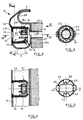
- the fixing device 10 consists of the bolt cover 9 and screws 6 is shown in more detail in Figures 3 to 6.
- the bolt cover 9 has on its outer face 11 fairing holes 12 for access.
- first cylindrical sockets 15 having a first end 16 integral with said external face 11, this first end 16 being, for example, in the example shown in Figures 3 to 6, welded to the circular edge 17 of said access holes 12.
- the two parts 11 and 14 of the bolt cover 9 can for example also be welded to one another to facilitate manufacture.
- the second end 18 of said first sockets 15 has four slots 19 in a slot.
- each first socket 15 is placed a second cylindrical socket 20 whose internal end is cut to form, on the one hand, two first legs 21 which, as can be seen in FIGS. 3 and 4, are slightly deformed outwards so as to fit into said cutouts 19 of the first socket 15 and, on the other hand, two second legs 22, one of which 22 a is shown in the lower half-view of FIG. 3, free position, folded at right angles towards the inside of the second socket 20 and slightly deformed inwardly and the other 22 b is shown in the upper half-view of FIG 3, engaged on the end 8a of the head 8 of the screw 6.
- the internal edge of each second tab 22 comprises, as can be seen in FIGS. 5 and 6, a cutout 23 in a semicircle which is slightly offset.
- the external end of the second socket 20 carries a cover 25 in which an oblong hole 26 is formed.
- the assembly method of the assembly which has just been described is as follows.
- the bolt cover 9 with internal sockets 15 being positioned on the parts to be assembled, ventilation cover 7 and annular flange 4 of the exhaust casing 2, the screws 6 are mounted and tightened in the tapped holes 5 of said flange passing through the access holes 12 as well as through fixing holes 27 drilled in the internal part 14 of the bolt cover 9 and the heads 8 of the screws 6 bearing on the edges of these holes 27.
- the second sockets 20 are then introduced towards the inside of the bolt cover 9 through the access holes 12 so as to snap the first legs 21 into the cutouts 19 of the first sockets 15 and to engage the cutouts 23 of the second legs 22 on the teeth 24 of the end 8 a of the head 8 of the screws 6.
- the teeth 24 are 12 in number and the cooperating cutouts 23 are offset by a twenty-fourth turn so to get one in guaranteed engagement of tooth 24 in cutout 23.
- the assembly obtained also retains its dismountability and intervention is made possible individually on the screws 6.
- the risks of premature wear following several assemblies / disassemblies are reduced because only an elastic deformation of the tabs of the second sleeve 20 occurs to ensure the locking of the entire fixing device.
- the bolt cover 9 further comprises on the downstream side an annular groove 28 where the upstream edges 29 of tiles 30 for thermal protection of the hub 3 of the casing are placed. exhaust 2 of the turbomachine.
Landscapes
- Engineering & Computer Science (AREA)
- General Engineering & Computer Science (AREA)
- Mechanical Engineering (AREA)
- Structures Of Non-Positive Displacement Pumps (AREA)
- Supercharger (AREA)
Claims (5)
Applications Claiming Priority (2)
| Application Number | Priority Date | Filing Date | Title |
|---|---|---|---|
| FR8717547 | 1987-12-16 | ||
| FR8717547A FR2624913B1 (fr) | 1987-12-16 | 1987-12-16 | Dispositif de fixation a vis d'une piece de revolution sur une bride annulaire de turbomachine |
Publications (2)
| Publication Number | Publication Date |
|---|---|
| EP0321344A1 EP0321344A1 (de) | 1989-06-21 |
| EP0321344B1 true EP0321344B1 (de) | 1991-05-29 |
Family
ID=9357919
Family Applications (1)
| Application Number | Title | Priority Date | Filing Date |
|---|---|---|---|
| EP88403191A Expired - Lifetime EP0321344B1 (de) | 1987-12-16 | 1988-12-15 | Schraubensicherungselement für Turbomaschine |
Country Status (4)
| Country | Link |
|---|---|
| US (1) | US4883407A (de) |
| EP (1) | EP0321344B1 (de) |
| DE (1) | DE3863064D1 (de) |
| FR (1) | FR2624913B1 (de) |
Families Citing this family (14)
| Publication number | Priority date | Publication date | Assignee | Title |
|---|---|---|---|---|
| US5090865A (en) * | 1990-10-22 | 1992-02-25 | General Electric Company | Windage shield |
| US5259725A (en) * | 1992-10-19 | 1993-11-09 | General Electric Company | Gas turbine engine and method of assembling same |
| US5316437A (en) * | 1993-02-19 | 1994-05-31 | General Electric Company | Gas turbine engine structural frame assembly having a thermally actuated valve for modulating a flow of hot gases through the frame hub |
| DE19727680B4 (de) * | 1997-06-30 | 2004-05-19 | Zf Sachs Ag | Schwungmassenvorrichtung mit einer Verliersicherung |
| US7704038B2 (en) * | 2006-11-28 | 2010-04-27 | General Electric Company | Method and apparatus to facilitate reducing losses in turbine engines |
| FR2925123A1 (fr) * | 2007-12-14 | 2009-06-19 | Snecma Sa | Etancheite de fixation de support de palier dans une turbomachine |
| US8292592B2 (en) * | 2008-04-02 | 2012-10-23 | United Technologies Corporation | Nosecone bolt access and aerodynamic leakage baffle |
| CH705514A1 (de) * | 2011-09-05 | 2013-03-15 | Alstom Technology Ltd | Gaskanal für eine Gasturbine sowie Gasturbine mit einem solchen Gaskanal. |
| US9790919B2 (en) * | 2014-02-25 | 2017-10-17 | General Electric Company | Joint assembly for rotor blade segments of a wind turbine |
| US11274563B2 (en) * | 2016-01-21 | 2022-03-15 | General Electric Company | Turbine rear frame for a turbine engine |
| US10294808B2 (en) * | 2016-04-21 | 2019-05-21 | United Technologies Corporation | Fastener retention mechanism |
| US10494936B2 (en) * | 2016-05-23 | 2019-12-03 | United Technologies Corporation | Fastener retention mechanism |
| US10563636B2 (en) | 2017-08-07 | 2020-02-18 | General Electric Company | Joint assembly for a wind turbine rotor blade |
| IT202100009716A1 (it) | 2021-04-16 | 2022-10-16 | Ge Avio Srl | Copertura di un dispositivo di fissaggio per una giunzione flangiata |
Family Cites Families (11)
| Publication number | Priority date | Publication date | Assignee | Title |
|---|---|---|---|---|
| FR483555A (fr) * | 1914-10-15 | 1917-07-20 | Henri Risser | Bouton à pression |
| US1328488A (en) * | 1919-03-22 | 1920-01-20 | Junius A Bowden | Dust-cap and attaching means therefor |
| US2930662A (en) * | 1956-11-01 | 1960-03-29 | Bristol Aero Engines Ltd | Supporting structure for a gas turbine bearing |
| BE570533A (de) * | 1957-08-22 | |||
| US3135309A (en) * | 1961-03-01 | 1964-06-02 | Illinois Tool Works | Self-retained sheet metal fastener |
| US3737660A (en) * | 1969-10-09 | 1973-06-05 | Hida X Ray | Apparatus for taking tomograms of parabolically curved objects |
| US3727660A (en) * | 1971-02-16 | 1973-04-17 | Gen Electric | Bolt retainer and compressor employing same |
| US4190397A (en) * | 1977-11-23 | 1980-02-26 | General Electric Company | Windage shield |
| GB2057617A (en) * | 1979-09-06 | 1981-04-01 | Rolls Royce | Bolt-retaining device |
| GB2071776A (en) * | 1980-03-19 | 1981-09-23 | Rolls Royce | Stator Vane Assembly |
| US4493597A (en) * | 1982-09-07 | 1985-01-15 | Eaton Corporation | Nut lock assembly |
-
1987
- 1987-12-16 FR FR8717547A patent/FR2624913B1/fr not_active Expired - Lifetime
-
1988
- 1988-12-15 DE DE8888403191T patent/DE3863064D1/de not_active Expired - Lifetime
- 1988-12-15 EP EP88403191A patent/EP0321344B1/de not_active Expired - Lifetime
- 1988-12-16 US US07/285,583 patent/US4883407A/en not_active Expired - Fee Related
Also Published As
| Publication number | Publication date |
|---|---|
| FR2624913B1 (fr) | 1990-04-20 |
| EP0321344A1 (de) | 1989-06-21 |
| DE3863064D1 (de) | 1991-07-04 |
| US4883407A (en) | 1989-11-28 |
| FR2624913A1 (fr) | 1989-06-23 |
Similar Documents
| Publication | Publication Date | Title |
|---|---|---|
| EP0321344B1 (de) | Schraubensicherungselement für Turbomaschine | |
| EP1584785B1 (de) | Kompensationsmasse zur Auswuchtung eines Rotors für einen Rotor eines Flugtriebwerks | |
| CA2824379C (fr) | Rotor de soufflante et turboreacteur associe | |
| FR2923527A1 (fr) | Etage de turbine ou de compresseur, en particulier de turbomachine | |
| EP0327771B1 (de) | Schraubensicherungselement für Turbomaschine | |
| EP1811131A2 (de) | Anordnung von Statorsektoren für einen Verdichter eines Turbotriebwerks | |
| FR2975449A1 (fr) | Dispositif de fixation d'une piece annulaire sur un arbre de turbomachine | |
| FR2901574A1 (fr) | Dispositif de guidage d'un flux d'air a l'entree d'une chambre de combustion dans une turbomachine | |
| CA2608402A1 (fr) | Dispositif d'accrochage d'un distributeur d'une turbine, turbine les comportant, et moteur d'aeronef en etant equipe | |
| EP2060751B1 (de) | Turbinen- oder Kompressorstufe eines Turbotriebwerks | |
| FR3063308A1 (fr) | Bouchon pour capot d'entree tournant de turbomachine, comprenant une paroi externe aerodynamique et un organe de fixation de cone | |
| WO2013182797A1 (fr) | Turbomachine comportant des moyens de fixation amont d'un tube de deshuilage | |
| EP1956297B1 (de) | Gasturbinenverbrennungskammer | |
| EP2060744B1 (de) | Turbinen- oder Kompressorstufe eines Turbotriebwerks | |
| CA2364128A1 (fr) | Systeme de retention des abes de type combine ou cascade | |
| FR3099801A1 (fr) | Ensemble pour une turbine de turbomachine | |
| FR2654776A1 (fr) | Dispositif et ecran pour la reduction des ruptures aerodynamiques dues a un joint, et conduite d'echappement tournante comportant un tel ecran. | |
| CA2577502C (fr) | Roue de rotor de turbomachine | |
| FR2922588A1 (fr) | Disque ou tambour de rotor d'une turbomachine | |
| FR3063309B1 (fr) | Capot d'entree tournant de turbomachine, comprenant une paroi externe aerodynamique et un organe de serrage de cone | |
| WO2014037653A1 (fr) | Rotor de soufflante, en particulier pour une turbomachine | |
| WO2021148756A1 (fr) | Ensemble récupérateur de fluide | |
| FR3108149A1 (fr) | Module de soufflante pour une turbomachine d’aeronef | |
| FR2949139A1 (fr) | Joint d'etancheite a labyrinthe pour turbomachine | |
| FR3102796A1 (fr) | Plateformes inter-aubes |
Legal Events
| Date | Code | Title | Description |
|---|---|---|---|
| PUAI | Public reference made under article 153(3) epc to a published international application that has entered the european phase |
Free format text: ORIGINAL CODE: 0009012 |
|
| 17P | Request for examination filed |
Effective date: 19890105 |
|
| AK | Designated contracting states |
Kind code of ref document: A1 Designated state(s): DE FR GB |
|
| 17Q | First examination report despatched |
Effective date: 19901017 |
|
| RAP1 | Party data changed (applicant data changed or rights of an application transferred) |
Owner name: SOCIETE NATIONALE D'ETUDE ET DE CONSTRUCTION DE MO |
|
| GRAA | (expected) grant |
Free format text: ORIGINAL CODE: 0009210 |
|
| AK | Designated contracting states |
Kind code of ref document: B1 Designated state(s): DE FR GB |
|
| REF | Corresponds to: |
Ref document number: 3863064 Country of ref document: DE Date of ref document: 19910704 |
|
| GBT | Gb: translation of ep patent filed (gb section 77(6)(a)/1977) | ||
| PLBE | No opposition filed within time limit |
Free format text: ORIGINAL CODE: 0009261 |
|
| STAA | Information on the status of an ep patent application or granted ep patent |
Free format text: STATUS: NO OPPOSITION FILED WITHIN TIME LIMIT |
|
| 26N | No opposition filed | ||
| PGFP | Annual fee paid to national office [announced via postgrant information from national office to epo] |
Ref country code: FR Payment date: 19951116 Year of fee payment: 8 |
|
| PGFP | Annual fee paid to national office [announced via postgrant information from national office to epo] |
Ref country code: GB Payment date: 19951206 Year of fee payment: 8 |
|
| PGFP | Annual fee paid to national office [announced via postgrant information from national office to epo] |
Ref country code: DE Payment date: 19960228 Year of fee payment: 8 |
|
| PG25 | Lapsed in a contracting state [announced via postgrant information from national office to epo] |
Ref country code: GB Effective date: 19961215 |
|
| GBPC | Gb: european patent ceased through non-payment of renewal fee |
Effective date: 19961215 |
|
| PG25 | Lapsed in a contracting state [announced via postgrant information from national office to epo] |
Ref country code: FR Effective date: 19970829 |
|
| PG25 | Lapsed in a contracting state [announced via postgrant information from national office to epo] |
Ref country code: DE Effective date: 19970902 |
|
| REG | Reference to a national code |
Ref country code: FR Ref legal event code: ST |