EP0321395A2 - Dispositif d'accouplement pour fraise tubulaire pour l'usinage du béton et de la pierre - Google Patents
Dispositif d'accouplement pour fraise tubulaire pour l'usinage du béton et de la pierre Download PDFInfo
- Publication number
- EP0321395A2 EP0321395A2 EP88810804A EP88810804A EP0321395A2 EP 0321395 A2 EP0321395 A2 EP 0321395A2 EP 88810804 A EP88810804 A EP 88810804A EP 88810804 A EP88810804 A EP 88810804A EP 0321395 A2 EP0321395 A2 EP 0321395A2
- Authority
- EP
- European Patent Office
- Prior art keywords
- coupling
- coupling part
- recess
- union nut
- parts
- Prior art date
- Legal status (The legal status is an assumption and is not a legal conclusion. Google has not performed a legal analysis and makes no representation as to the accuracy of the status listed.)
- Granted
Links
- 230000008878 coupling Effects 0.000 title claims abstract description 88
- 238000010168 coupling process Methods 0.000 title claims abstract description 88
- 238000005859 coupling reaction Methods 0.000 title claims abstract description 88
- 239000004575 stone Substances 0.000 title claims description 4
- 238000003801 milling Methods 0.000 claims description 22
- 230000000295 complement effect Effects 0.000 claims description 3
- 239000002826 coolant Substances 0.000 claims description 2
- 238000007789 sealing Methods 0.000 claims description 2
- 230000005540 biological transmission Effects 0.000 abstract description 7
- 238000010276 construction Methods 0.000 description 1
- 239000000110 cooling liquid Substances 0.000 description 1
- 239000000498 cooling water Substances 0.000 description 1
- 239000010432 diamond Substances 0.000 description 1
- 238000004519 manufacturing process Methods 0.000 description 1
- 238000000034 method Methods 0.000 description 1
- 230000007704 transition Effects 0.000 description 1
- XLYOFNOQVPJJNP-UHFFFAOYSA-N water Substances O XLYOFNOQVPJJNP-UHFFFAOYSA-N 0.000 description 1
Images

Classifications
-
- B—PERFORMING OPERATIONS; TRANSPORTING
- B23—MACHINE TOOLS; METAL-WORKING NOT OTHERWISE PROVIDED FOR
- B23B—TURNING; BORING
- B23B51/00—Tools for drilling machines
- B23B51/04—Drills for trepanning
- B23B51/0473—Details about the connection between the driven shaft and the tubular cutting part; Arbors
-
- B—PERFORMING OPERATIONS; TRANSPORTING
- B23—MACHINE TOOLS; METAL-WORKING NOT OTHERWISE PROVIDED FOR
- B23B—TURNING; BORING
- B23B31/00—Chucks; Expansion mandrels; Adaptations thereof for remote control
- B23B31/02—Chucks
- B23B31/10—Chucks characterised by the retaining or gripping devices or their immediate operating means
- B23B31/11—Retention by threaded connection
-
- B—PERFORMING OPERATIONS; TRANSPORTING
- B28—WORKING CEMENT, CLAY, OR STONE
- B28D—WORKING STONE OR STONE-LIKE MATERIALS
- B28D1/00—Working stone or stone-like materials, e.g. brick, concrete or glass, not provided for elsewhere; Machines, devices, tools therefor
- B28D1/02—Working stone or stone-like materials, e.g. brick, concrete or glass, not provided for elsewhere; Machines, devices, tools therefor by sawing
- B28D1/04—Working stone or stone-like materials, e.g. brick, concrete or glass, not provided for elsewhere; Machines, devices, tools therefor by sawing with circular or cylindrical saw-blades or saw-discs
- B28D1/041—Working stone or stone-like materials, e.g. brick, concrete or glass, not provided for elsewhere; Machines, devices, tools therefor by sawing with circular or cylindrical saw-blades or saw-discs with cylinder saws, e.g. trepanning; saw cylinders, e.g. having their cutting rim equipped with abrasive particles
-
- Y—GENERAL TAGGING OF NEW TECHNOLOGICAL DEVELOPMENTS; GENERAL TAGGING OF CROSS-SECTIONAL TECHNOLOGIES SPANNING OVER SEVERAL SECTIONS OF THE IPC; TECHNICAL SUBJECTS COVERED BY FORMER USPC CROSS-REFERENCE ART COLLECTIONS [XRACs] AND DIGESTS
- Y10—TECHNICAL SUBJECTS COVERED BY FORMER USPC
- Y10T—TECHNICAL SUBJECTS COVERED BY FORMER US CLASSIFICATION
- Y10T279/00—Chucks or sockets
- Y10T279/17—Socket type
- Y10T279/17017—Self-centering of floating
-
- Y—GENERAL TAGGING OF NEW TECHNOLOGICAL DEVELOPMENTS; GENERAL TAGGING OF CROSS-SECTIONAL TECHNOLOGIES SPANNING OVER SEVERAL SECTIONS OF THE IPC; TECHNICAL SUBJECTS COVERED BY FORMER USPC CROSS-REFERENCE ART COLLECTIONS [XRACs] AND DIGESTS
- Y10—TECHNICAL SUBJECTS COVERED BY FORMER USPC
- Y10T—TECHNICAL SUBJECTS COVERED BY FORMER US CLASSIFICATION
- Y10T403/00—Joints and connections
- Y10T403/67—Thimble: screw or cam
-
- Y—GENERAL TAGGING OF NEW TECHNOLOGICAL DEVELOPMENTS; GENERAL TAGGING OF CROSS-SECTIONAL TECHNOLOGIES SPANNING OVER SEVERAL SECTIONS OF THE IPC; TECHNICAL SUBJECTS COVERED BY FORMER USPC CROSS-REFERENCE ART COLLECTIONS [XRACs] AND DIGESTS
- Y10—TECHNICAL SUBJECTS COVERED BY FORMER USPC
- Y10T—TECHNICAL SUBJECTS COVERED BY FORMER US CLASSIFICATION
- Y10T408/00—Cutting by use of rotating axially moving tool
- Y10T408/94—Tool-support
- Y10T408/95—Tool-support with tool-retaining means
- Y10T408/957—Tool adapter
-
- Y—GENERAL TAGGING OF NEW TECHNOLOGICAL DEVELOPMENTS; GENERAL TAGGING OF CROSS-SECTIONAL TECHNOLOGIES SPANNING OVER SEVERAL SECTIONS OF THE IPC; TECHNICAL SUBJECTS COVERED BY FORMER USPC CROSS-REFERENCE ART COLLECTIONS [XRACs] AND DIGESTS
- Y10—TECHNICAL SUBJECTS COVERED BY FORMER USPC
- Y10T—TECHNICAL SUBJECTS COVERED BY FORMER US CLASSIFICATION
- Y10T409/00—Gear cutting, milling, or planing
- Y10T409/30—Milling
- Y10T409/30952—Milling with cutter holder
Definitions
- the invention relates to a coupling device for connecting a rotating drive unit with a hollow milling cutter for processing concrete and stone.
- a coupling device for connecting a rotating drive unit with a hollow milling cutter for processing concrete and stone.
- a relatively large diameter up to about 500 mm
- a correspondingly large drive power e.g. about 10 KW
- threaded connections between the drive unit and the hollow milling cutter become so jammed by the transmission of the high torque that such a threaded connection can be loosened only with great difficulty when the hollow milling cutter is replaced.
- With the forces required for loosening a deformation of the usually relatively thin-walled shell of the hollow milling cutter can easily occur, as a result of which the milling cutter becomes unusable.
- such a cutter change with parts jammed into one another is time-consuming and tedious and the suitable tools and aids are often not available on construction sites.
- both coupling parts must be easy and quick to assemble from the separated state, whereby it must be taken into account that both coupling parts are rigidly attached to machine parts, some of which are heavy, and a laborious search for the angularly and axially interlocking position is not reasonable .
- the object to be achieved with the invention is to create a coupling device between a hollow milling cutter and its motor-rotatable drive unit, which is suitable for the transmission of high torques, but the hollow milling cutter can still be easily loosened and replaced, the coupling device in the separated and in the assembled state has a short overall height, and the coupling parts are to be joined together while avoiding a complicated procedure.
- the torque is only transmitted through axially interlocking parts.
- the union nut only serves to hold the two coupling parts in the engaged state without being involved in the transmission of the torque. As a result, the two coupling parts can be easily loosened and separated from one another after the union nut has been screwed back.
- the difficulty encountered in assembling the coupling parts in such a torque-transmitting two-part clutch, that the two coupling parts must have a corresponding axial position and also a corresponding rotational position before they mesh, is solved in the coupling device according to the invention by the fact that centering elements are present, with which an axial first matching position can be reached, whereupon by rotating the one coupling part relative to the other - while maintaining the axially matching position - a matching rotational position can be easily reached, so that afterwards the two coupling parts can assume their joined, non-positive position.
- the short height makes it easier to replace the milling cutters.
- a central through opening in both coupling parts can be used to supply coolant.
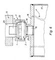
- the coupling serves for the detachable connection of a hollow milling cutter 14 for concrete and stone processing with a rotating drive unit 13.
- an upper, first coupling piece 1 contains a threaded pin 4, which is intended for this purpose in the spindle 28 of a preferably hydraulic one Drive unit 13 to be screwed in until its shoulder 5 rests against the end face of the spindle 28.
- a recess 7 deviating from the circular shape, the contour of which can be seen in FIG. 1. This contour is intended for receiving an approximately cruciform counterpart of a second, lower coupling piece 2.
- this recess 7 is essentially composed of a circular recess 12 and four semicircular recesses 9 projecting radially therefrom.
- the transition zones each form the actual contact surfaces a and thus the adjacent parts 27 with the side surfaces 22 for the shoulder 20 of the counterpart 2.
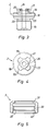
- a second, lower coupling part 2 is intended for connection to a hollow milling cutter 14.
- a pin 15 provided with an external thread is screwed into a milling cutter flange 16 (FIG. 6) until its shoulder 25 lies against the end face of the collar 26 of the milling cutter flange 16.
- the area above contains a short thread 18 on the outside with, for example, approximately three threads.
- the adjoining area contains the coupling projection 20, which is intended to engage in the complementary recess 7 of the first coupling part 1.
- This coupling projection 20 is essentially designed as a cross 20, the four legs of which lie on the outside on a circular cylinder jacket 21 (FIG. 4).
- the area 22 located between the cross legs is rounded and part of a circle.
- the diameter of the circumferential circle 21 of the cross leg 20 is slightly smaller than the diameter of the centering recess 8 in the first coupling part 1. This makes it easier to center the two coupling parts 1, 2.
- the two parts are joined together in such a way that the two coupling parts are initially centered in any mutual rotational position in the recess 8. Then the one relative to the other coupling part 1, 2 is rotated until the cross 20 is in an angularly coincident position with the complementary recess 7 and the two parts then snap into one another by axial movement with virtually no play.
- the cross-leg side surfaces 22 bear against the regions of the first coupling part 1 denoted by a and bring about a non-positive connection.
- the side surfaces 22 of the cross leg 20 run at right angles to the surface 19, that is to say in the axial direction of the coupling part 2, as well as the wall of the recess 7 with the areas a.
- In the center of the coupling part 2 there is a through hole 23, at the upper end of which a sealing ring 24 is inserted, which slightly projects beyond the upper end face in the non-assembled state.
- the two coupling parts 1, 2 are thus joined together by pure axial movements and separated from one another.
- the union nut 3 only serves to hold the two coupling parts 1, 2 in the assembled state, without it participating in the transmission of the torque.
- the union nut 3 is screwed onto the short thread 18, the inwardly projecting annular surface 31 comes to bear against the shoulder 5, as a result of which the two coupling parts 1, 2 are pulled toward one another until the two surfaces 19 and 11 come to rest.
- This quick coupling in which the union nut 3 is provided with a polygonal outer surface, preferably in the form of a hexagon, can also be easily released after the transmission of high torques.
- the union nut 3 is screwed up until the short thread 18 is disengaged from the thread 18.
- the lower coupling part 2 together with the hollow milling cutter 14 can then be pulled out of the upper coupling part 1 by an axial movement downwards.
- the two coupling parts 1, 2 can therefore not get stuck on their axially or vertically running force-transmitting contact surfaces, which is why a change of hollow milling cutters can be carried out simply and quickly.
- the two coupling parts 1, 2 can be easily manufactured by CNC machines.
- the hollow milling cutter 14 At the lower end of the jacket 17 of the hollow milling cutter 14 there are usually soldered cutting inserts with diamonds.
- the diameter of these hollow milling cutters 14 can be up to approximately 500 mm.
- annular flange could also be used be present, which is rigidly screwed to the cutter flange 16 by a plurality of axial screws.
- the coupling part provided with a projecting cross 20 it would also be possible for the coupling part provided with a projecting cross 20 to be arranged at the top and the coupling part provided with the recess 7 at the bottom.
- a protruding centering pin could be used in a coupling part 1 or 2 in its through hole 10, 23, which loosely engages in the through hole of the other coupling part. Longitudinal grooves would have to be provided in this centering pin for passage of the cooling water or it should be designed as a tube.
- the interlocking coupling parts could also have a different, in particular polygonal, shape, which can only be inserted and separated from one another by axial movement.
Landscapes
- Engineering & Computer Science (AREA)
- Mechanical Engineering (AREA)
- Mining & Mineral Resources (AREA)
- Processing Of Stones Or Stones Resemblance Materials (AREA)
- Milling Processes (AREA)
Applications Claiming Priority (2)
| Application Number | Priority Date | Filing Date | Title |
|---|---|---|---|
| CH474887 | 1987-12-05 | ||
| CH4748/87 | 1987-12-05 |
Publications (3)
| Publication Number | Publication Date |
|---|---|
| EP0321395A2 true EP0321395A2 (fr) | 1989-06-21 |
| EP0321395A3 EP0321395A3 (en) | 1990-06-27 |
| EP0321395B1 EP0321395B1 (fr) | 1992-07-08 |
Family
ID=4281840
Family Applications (1)
| Application Number | Title | Priority Date | Filing Date |
|---|---|---|---|
| EP88810804A Expired - Lifetime EP0321395B1 (fr) | 1987-12-05 | 1988-11-23 | Dispositif d'accouplement pour fraise tubulaire pour l'usinage du béton et de la pierre |
Country Status (3)
| Country | Link |
|---|---|
| US (1) | US4923344A (fr) |
| EP (1) | EP0321395B1 (fr) |
| DE (1) | DE3872683D1 (fr) |
Cited By (3)
| Publication number | Priority date | Publication date | Assignee | Title |
|---|---|---|---|---|
| WO1997031743A1 (fr) * | 1996-03-02 | 1997-09-04 | Armeg Limited | Foret-aleseur |
| DE19650441A1 (de) * | 1996-12-05 | 1998-06-18 | Joerg Weinmann | Maschine für die Tiefen- und Oberflächenbearbeitung von Gegenständen |
| WO2007060653A1 (fr) * | 2005-11-22 | 2007-05-31 | Iscar Ltd. | Ensemble outil de coupe |
Families Citing this family (11)
| Publication number | Priority date | Publication date | Assignee | Title |
|---|---|---|---|---|
| DE59100622D1 (de) * | 1990-04-10 | 1994-01-05 | Hydrostress Ag Pfaeffikon | Fahrbares, hydraulisches Antriebsaggregat. |
| IL113698A (en) * | 1995-05-11 | 1998-12-06 | Iscar Ltd | Cutting tool assembly |
| SE511429C2 (sv) | 1996-09-13 | 1999-09-27 | Seco Tools Ab | Verktyg, skärdel, verktygskropp för skärande bearbetning samt metod för montering av skärdel till verktygskropp |
| DE10256043A1 (de) * | 2002-11-30 | 2004-06-09 | Hilti Ag | Werkzeugaufnahme für Kernbohrkronen |
| WO2005063458A1 (fr) * | 2003-12-25 | 2005-07-14 | Shibuya Company, Ltd. | Couronne de carottage pour carottier |
| WO2011134040A1 (fr) * | 2010-04-30 | 2011-11-03 | Shunderson Communications, Inc. | Appareil d'échantillonnage rotatif entraîné par moteur, possédant des outils de coupe amovibles pour recueillir la matière |
| US9643262B2 (en) | 2013-07-25 | 2017-05-09 | Kennametal Inc. | Coupling mechanism for cutting tool |
| US9643264B2 (en) | 2013-07-25 | 2017-05-09 | Kennametal Inc. | Coupling mechanism for cutting tool |
| US9889509B2 (en) | 2014-05-05 | 2018-02-13 | Kennametal Inc. | Cutter heads with improved coupling |
| CN215256059U (zh) | 2021-02-10 | 2021-12-21 | 米沃奇电动工具公司 | 钻孔取芯机组件 |
| EP4313457A4 (fr) | 2021-04-02 | 2025-03-05 | Milwaukee Electric Tool Corporation | Carottier |
Family Cites Families (11)
| Publication number | Priority date | Publication date | Assignee | Title |
|---|---|---|---|---|
| US2767564A (en) * | 1954-06-04 | 1956-10-23 | Frank L Green | Tool holder |
| US2898118A (en) * | 1955-09-15 | 1959-08-04 | Frederick H Smith | Adjustable drill holder |
| GB833802A (en) * | 1957-06-29 | 1960-04-27 | Bailey Brothers Hot Pressings | Improvements relating to detachable joints for connection rods |
| US3162457A (en) * | 1962-07-25 | 1964-12-22 | Beaver Tool & Engineering Corp | Axially adjustable cutting tool |
| US3364798A (en) * | 1966-02-17 | 1968-01-23 | Empire Tool | Floating reamer holder |
| CH457053A (de) * | 1967-04-18 | 1968-05-31 | Bbc Brown Boveri & Cie | Kupplung für die Übertragung grosser Drehmomente |
| US3524663A (en) * | 1969-05-16 | 1970-08-18 | Mueller Co | Releasable drive coupling |
| US3736011A (en) * | 1972-03-02 | 1973-05-29 | Tool & Equipment Mfg Co Inc Mo | Quick disconnect tool coupling |
| US3835666A (en) * | 1973-08-30 | 1974-09-17 | J Hoffman | Versatile tool holder |
| US4487271A (en) * | 1982-02-12 | 1984-12-11 | Pomeroy Dan M | Portable core drill |
| US4655630A (en) * | 1985-12-31 | 1987-04-07 | Dana Corporation | Robot arm end adapter |
-
1988
- 1988-11-23 EP EP88810804A patent/EP0321395B1/fr not_active Expired - Lifetime
- 1988-11-23 DE DE8888810804T patent/DE3872683D1/de not_active Expired - Fee Related
- 1988-12-05 US US07/280,380 patent/US4923344A/en not_active Expired - Fee Related
Cited By (3)
| Publication number | Priority date | Publication date | Assignee | Title |
|---|---|---|---|---|
| WO1997031743A1 (fr) * | 1996-03-02 | 1997-09-04 | Armeg Limited | Foret-aleseur |
| DE19650441A1 (de) * | 1996-12-05 | 1998-06-18 | Joerg Weinmann | Maschine für die Tiefen- und Oberflächenbearbeitung von Gegenständen |
| WO2007060653A1 (fr) * | 2005-11-22 | 2007-05-31 | Iscar Ltd. | Ensemble outil de coupe |
Also Published As
| Publication number | Publication date |
|---|---|
| EP0321395A3 (en) | 1990-06-27 |
| DE3872683D1 (de) | 1992-08-13 |
| EP0321395B1 (fr) | 1992-07-08 |
| US4923344A (en) | 1990-05-08 |
Similar Documents
| Publication | Publication Date | Title |
|---|---|---|
| DE865561C (de) | Werkzeugkopf | |
| DE3783140T2 (de) | Werkzeughalter und verfahren zur montage mit einfacher demontage. | |
| DE3545651C2 (fr) | ||
| EP0563542B1 (fr) | Moyens pour connecter des pièces de façon détachable | |
| EP0747606B1 (fr) | Serrure pour fixation d'un manchon d'accouplement | |
| EP0321395B1 (fr) | Dispositif d'accouplement pour fraise tubulaire pour l'usinage du béton et de la pierre | |
| EP0345373B1 (fr) | Boulon | |
| DE1810223A1 (de) | UEberlastungskupplung mit Spannkopf | |
| DE3532891A1 (de) | Werkzeugkupplung | |
| DE2732677A1 (de) | Spannzange | |
| DE112014006855T5 (de) | Extruderschneckenwellen-Ausrichtungsgerät und -verfahren | |
| EP0156993A1 (fr) | Elément surcharge pour accouplements avec limiteur de couple | |
| DE3616230C2 (fr) | ||
| DE1500942B1 (de) | Anwendung einer schnellkupplung bei einer schraubverbindung | |
| DE1502035A1 (de) | Spannfutter mit Schwenkarmen | |
| DE2831140C2 (fr) | ||
| CH654232A5 (de) | Bohrwerkzeug. | |
| DE2541123A1 (de) | Vorrichtung zum befestigen von spanabhebenden werkzeugen an maschinenspindeln | |
| DE19911141A1 (de) | Werkzeughalter | |
| EP0282786B1 (fr) | Dispositif d'accouplement pour pièces rotatives à connecter | |
| DE4117765A1 (de) | Schnittstelle | |
| DE3521223A1 (de) | Vorrichtung zum blockieren mit widerstand gegen eventuelle axiale belastungen von lagern oder koerpern mit rotierenden elementen an achsen oder wellen | |
| DE1806131A1 (de) | Schnell loesbare Kupplung | |
| DE589451C (de) | Verbindung, insbesondere fuer zusammengesetzte Kurbelwellen | |
| DE892700C (de) | Zahnrad |
Legal Events
| Date | Code | Title | Description |
|---|---|---|---|
| PUAI | Public reference made under article 153(3) epc to a published international application that has entered the european phase |
Free format text: ORIGINAL CODE: 0009012 |
|
| AK | Designated contracting states |
Kind code of ref document: A2 Designated state(s): CH DE FR GB IT LI SE |
|
| PUAL | Search report despatched |
Free format text: ORIGINAL CODE: 0009013 |
|
| AK | Designated contracting states |
Kind code of ref document: A3 Designated state(s): CH DE FR GB IT LI SE |
|
| 17P | Request for examination filed |
Effective date: 19900712 |
|
| 17Q | First examination report despatched |
Effective date: 19910515 |
|
| GRAA | (expected) grant |
Free format text: ORIGINAL CODE: 0009210 |
|
| AK | Designated contracting states |
Kind code of ref document: B1 Designated state(s): CH DE FR GB IT LI SE |
|
| REF | Corresponds to: |
Ref document number: 3872683 Country of ref document: DE Date of ref document: 19920813 |
|
| GBT | Gb: translation of ep patent filed (gb section 77(6)(a)/1977) | ||
| ITF | It: translation for a ep patent filed | ||
| ET | Fr: translation filed | ||
| PLBE | No opposition filed within time limit |
Free format text: ORIGINAL CODE: 0009261 |
|
| STAA | Information on the status of an ep patent application or granted ep patent |
Free format text: STATUS: NO OPPOSITION FILED WITHIN TIME LIMIT |
|
| 26N | No opposition filed | ||
| PGFP | Annual fee paid to national office [announced via postgrant information from national office to epo] |
Ref country code: CH Payment date: 19941004 Year of fee payment: 7 |
|
| PGFP | Annual fee paid to national office [announced via postgrant information from national office to epo] |
Ref country code: FR Payment date: 19941006 Year of fee payment: 7 |
|
| PGFP | Annual fee paid to national office [announced via postgrant information from national office to epo] |
Ref country code: GB Payment date: 19941115 Year of fee payment: 7 |
|
| PGFP | Annual fee paid to national office [announced via postgrant information from national office to epo] |
Ref country code: SE Payment date: 19941128 Year of fee payment: 7 |
|
| PGFP | Annual fee paid to national office [announced via postgrant information from national office to epo] |
Ref country code: DE Payment date: 19941230 Year of fee payment: 7 |
|
| EAL | Se: european patent in force in sweden |
Ref document number: 88810804.0 |
|
| PG25 | Lapsed in a contracting state [announced via postgrant information from national office to epo] |
Ref country code: GB Effective date: 19951123 |
|
| PG25 | Lapsed in a contracting state [announced via postgrant information from national office to epo] |
Ref country code: SE Effective date: 19951124 |
|
| PG25 | Lapsed in a contracting state [announced via postgrant information from national office to epo] |
Ref country code: LI Effective date: 19951130 Ref country code: CH Effective date: 19951130 |
|
| REG | Reference to a national code |
Ref country code: CH Ref legal event code: PL |
|
| GBPC | Gb: european patent ceased through non-payment of renewal fee |
Effective date: 19951123 |
|
| PG25 | Lapsed in a contracting state [announced via postgrant information from national office to epo] |
Ref country code: FR Effective date: 19960731 |
|
| PG25 | Lapsed in a contracting state [announced via postgrant information from national office to epo] |
Ref country code: DE Effective date: 19960801 |
|
| EUG | Se: european patent has lapsed |
Ref document number: 88810804.0 |
|
| REG | Reference to a national code |
Ref country code: FR Ref legal event code: ST |
|
| PG25 | Lapsed in a contracting state [announced via postgrant information from national office to epo] |
Ref country code: IT Free format text: LAPSE BECAUSE OF NON-PAYMENT OF DUE FEES;WARNING: LAPSES OF ITALIAN PATENTS WITH EFFECTIVE DATE BEFORE 2007 MAY HAVE OCCURRED AT ANY TIME BEFORE 2007. THE CORRECT EFFECTIVE DATE MAY BE DIFFERENT FROM THE ONE RECORDED. Effective date: 20051123 |