EP0321458B1 - Procede de refection d'une jante/roue - Google Patents
Procede de refection d'une jante/roue Download PDFInfo
- Publication number
- EP0321458B1 EP0321458B1 EP87903783A EP87903783A EP0321458B1 EP 0321458 B1 EP0321458 B1 EP 0321458B1 EP 87903783 A EP87903783 A EP 87903783A EP 87903783 A EP87903783 A EP 87903783A EP 0321458 B1 EP0321458 B1 EP 0321458B1
- Authority
- EP
- European Patent Office
- Prior art keywords
- rim
- wheel
- chamber
- refinishing
- coating
- Prior art date
- Legal status (The legal status is an assumption and is not a legal conclusion. Google has not performed a legal analysis and makes no representation as to the accuracy of the status listed.)
- Expired - Lifetime
Links
Images



Classifications
-
- B—PERFORMING OPERATIONS; TRANSPORTING
- B60—VEHICLES IN GENERAL
- B60B—VEHICLE WHEELS; CASTORS; AXLES FOR WHEELS OR CASTORS; INCREASING WHEEL ADHESION
- B60B21/00—Rims
-
- B—PERFORMING OPERATIONS; TRANSPORTING
- B05—SPRAYING OR ATOMISING IN GENERAL; APPLYING FLUENT MATERIALS TO SURFACES, IN GENERAL
- B05B—SPRAYING APPARATUS; ATOMISING APPARATUS; NOZZLES
- B05B13/00—Machines or plants for applying liquids or other fluent materials to surfaces of objects or other work by spraying, not covered by groups B05B1/00 - B05B11/00
- B05B13/02—Means for supporting work; Arrangement or mounting of spray heads; Adaptation or arrangement of means for feeding work
- B05B13/0221—Means for supporting work; Arrangement or mounting of spray heads; Adaptation or arrangement of means for feeding work characterised by the means for moving or conveying the objects or other work, e.g. conveyor belts
- B05B13/0228—Means for supporting work; Arrangement or mounting of spray heads; Adaptation or arrangement of means for feeding work characterised by the means for moving or conveying the objects or other work, e.g. conveyor belts the movement of the objects being rotative
-
- B—PERFORMING OPERATIONS; TRANSPORTING
- B05—SPRAYING OR ATOMISING IN GENERAL; APPLYING FLUENT MATERIALS TO SURFACES, IN GENERAL
- B05B—SPRAYING APPARATUS; ATOMISING APPARATUS; NOZZLES
- B05B14/00—Arrangements for collecting, re-using or eliminating excess spraying material
- B05B14/40—Arrangements for collecting, re-using or eliminating excess spraying material for use in spray booths
- B05B14/43—Arrangements for collecting, re-using or eliminating excess spraying material for use in spray booths by filtering the air charged with excess material
Definitions
- the present invention is directed to refinishing or reconditioning rims or wheels of motor vehicles, such as trucks, automobiles, tractors, trailers, or the like.
- a truck rim is very rarely serviced from the day a tire is first mounted thereon and any number of retreads or new tires are remounted thereon.
- Such truck rims or wheels are subject to virtually constant use under most adverse conditions of nature, terrain and the like. Quite simply, the more commercial vehicles are used or are "on the road,” the more profitable is the return on investment. Accordingly, the wheels and rims are normally removed from trucks, tractors, trailers, or the like, new tires or retreads are mounted thereon, and these rims and wheels are returned to service with most unfortunate consequences, as evidenced by recent national reports confirming the high incidents of large vehicle accidents in proportion to the lesser number of such vehicles on the road as compared to passenger automobiles.
- the present invention provides a novel method of refinishing truck or similar vehicle wheels and rims so that when remounted with retreads or new tires on vehicles, the safety factor of the refinished rims and/or wheels are comparable and even better than when new.
- the present invention is directed to a novel method of refinishing a rim/wheel comprising the steps of placing a rim/wheel in a first chamber, maintaining the axis of the rim/wheel in a generally horizontal plane while the rim/wheel is in the first chamber, performing a hot liquid cleaning operation upon the rim/wheel while the rim/wheel is in the first chamber, transferring the rim/wheel after the hot liquid cleaning form the first chamber to a second chamber, shot blast cleaning the rim/wheel while the rim/wheel is in the second chamber, transferring the rim/wheel after the shot blast cleaning from the second chamber to a third chamber, applying an air-impervious coating of resilient protective synthetic polymeric/copolymeric material upon all surfaces of the rim/wheel while the rim/wheel is in the third chamber, and removing the rim/wheel from the third chamber for subsequent processing.
- the rim/wheel is preferably rotated in both chambers when its axis is disposed in a generally horizontal plane and the coating of polymeric material is applied by spraying when the rim/wheel is disposed in two positions with the axis thereof respectively vertical and horizontal.
- Another object of this invention is to provide a novel refinishing method in which the rim/wheel is elevated from floor level over an arcuate path of travel to the first chamber, conveyed form the first chamber to the second chamber, painted and subsequently relowered along an arcuate path back to floor level.
- Still another object of this invention is to provide a novel refinishing method as aforesaid wherein an ejection mechanism is utilized with each chamber to effectively eject each rim/wheel by rotation thereof along its axis.
- FIGURE 1 is a front perspective view of a novel refinishing apparatus or machine of this invention, and illustrates a rim/wheel in phantom outline progressively moving from right-to-left between an elevating station, a pressurized hot liquid washing and degreasing station, a shot-blasting station, a painting station, and a lowering station.
- FIGURE 2 is a highly schematic front elevational view of the refinishing apparatus of Figure 1, and illustrates the various stations with the elevating and lower stations rotated 90 degrees for clarity.
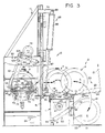
- FIGURE 3 is an enlarged cross-sectional view taken generally along line 3-3 of Figure 1, and illustrates details of the high-pressure cleaning and degreasing station, a rim/wheel ejector thereof, and a pivoting platform at the elevating station.
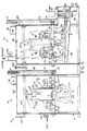
- FIGURE 4 which appears on the sheet of drawings containing Figure 2, is a fragmentary cross-sectional view taken generally along line 4-4 of Figure 2, and illustrates a rim/wheel in the shot blast chamber.
- FIGURE 5 is a vertical sectional view through the washing and degreasing chamber and the shot blast cleaning chamber, and illustrates details of the structures thereof and the manner in which a rim/wheel is cleaned thereby.
- FIGURE 6 is an enlarged cross-sectional view taken generally along line 6-6 of Figure 2, and illustrates a rim/wheel being sprayed with polymeric material during the rotation of the rim/wheel about a horizontal axis.
- FIGURE 7 is an enlarged fragmentary sectional view taken generally along line 7-7 of Figure 2, and illustrates a rim/wheel being sprayed while rotated about a horizontal axis and subsequently being reoriented with its axis vertical for subsequent spraying.
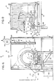
- FIGURE 8 which appears on the sheet of drawings containing Figure 6, is an enlarged cross-sectional view taken generally along line 8-8 of Figure 7, and illustrates the synthetic polymeric protective material being applied to the rim/wheel during the rotation thereof about a vertical axis.
- a novel machine or apparatus constructed in accordance with this invention for refinishing wheels or rims R of relatively large vehicles, such as trucks, tractors, trailers, and the like, is generally designated by the reference numeral 10.
- the machine 10 includes a frame or framework 11, an elevating station 12 for elevating each rim or wheel R (hereinafter rim/wheel R ) from ground level to a high-pressure, hot water washing and degreasing station 13, a shot-blasting station 14, a polymeric resin coating or painting station 15 and a lowering or discharge station 16.
- a second rim/wheel elevating station 17 is utilized to lift rims/wheels R from ground level directly to the shot blast station 14 thereby by-passing the high-pressure, hot water washing and degreasing station 13 should rims/wheels R be sufficiently free of grease, grime, dirt and the like for direct shot-blasting at the shot blast station 14.
- Conveyor means 18 which will be described more fully hereinafter convey or transfer each rim/wheel from right-to-left, as viewed in Figures 1 and 2, during the refinishing thereof.
- the elevating stations 12, 17 and the lowering station 16 are virtually identical in construction, and each includes means in the form of an L-shaped platform 20 defined by a base plate 21 and a ramp plate 22 which is welded to the base plate 21 at substantially 90 degrees thereto. Each ramp plate 22 is also welded to generally parallel side guide plates 23.
- a pair of cylindrical sleeves 24 ( Figure 7) are welded or otherwise secured to an upper end portion (unnumbered) of each of the ramp plates 22, and a cylindrical pivot pin 25 is received in and projects outwardly of the cylindrical sleeves 24.
- the sleeves 24 are welded or adjustably locked to the pivot pin 25 by radial set screws or bolts 26.
- the ends of each pivot pin 25 are journalled for rotation in bearing blocks 27 which are suitably welded or bolted to the frame 11.
- Means 30 in the form of a fluid cylinder 31 housing a reciprocal piston rod 32 is provided for pivoting each platform 20 between the positions thereof shown in Figure 1 at which the base plates 21 rest upon and are generally parallel to the support surface S′ of the machine 10, and the positions shown in phantom outline in Figures 3 and 6 at which the ramp plates 22 are disposed generally in a horizontal plane.
- a conventional pivotal connection 33 ( Figure 3) connects each cylinder 31 to an appropriate portion of the frame 11 and a like conventional pivotal connection 34 pivotally connects each piston rod 32 to the associated ramp plate 22.
- a fluid pressure source (not shown) is connected by conventional lines (also not shown) to the head and rod ends of the cylinder 31 and by operating appropriate foot pedals 35 (Figure 1) an operator can selectively extend or retract tie piston rods 32 relative to the cylinders 31.
- an operator can selectively extend or retract tie piston rods 32 relative to the cylinders 31.
- the piston rod 32 will be extended thereby pivoting the platform 20 ( Figure 3) from the solid to the phantom outline position in Figure 3 about a generally horizontal axis defined by the pivot pin 25.
- each refinished rim/wheel R is rolled upon the ramp plate 22 when in a horizontal position after which the associated piston rod 32 is retracted into the cylinder 31 to lower the refinished rim/wheel R to the surface S′ , again along an arcuate path of travel A 1 ( Figure 2).
- the conveying means 18 ( Figures 1, 2 and 3) run the length of the machine 10 and are defined by two generally cylindrical rollers 41, 42 transversely spaced from each other ( Figures 3 and 4) in generally parallel relationship and mounted for rotation at opposite ends of the machine 10 in journals 43, 44, respectively. Whhile the rollers 41, 42 are generally parallel to each other, as viewed along the length thereof, the elevations of upper surfaces (unnumbered) are not aligned and, in fact, cross at approximately the mid-point of the length of the rollers 41, 42, as is best illustrated in Figure 2.
- the left-hand end of the roller 41 in Figure 2 is shown elevated above the left-hand end of the roller 42, whereas the right-hand end of the roller 42 is above the right-hand end of the roller 41.
- the axes of the rollers 41, 42 cross substantially mid-way between the ends of the rollers 41, 42, and the reason therefor is to advance, convey or transport the rims/wheels from right-to-left, as viewed in Figures 1 and 2, when the rollers 41, 42 are rotated in the same direction, which is clockwise in Figure 3.
- the rollers 41, 42 are driven clockwise by means of a conventional electrical motor 45 ( Figure 3) having a pulley 46 rotated in a clockwise direction to similarly drive a pulley belt 47 which is in turn entrained about pulleys 48, 49 connected to the respective rollers 41, 42.
- the motor 45 is selectively energized from an electrical power source (not shown) by manipulating conventional switches 51 ( Figure 1).
- the rim wheel R supported thereby on its beads B 1 is rotated counterclockwise, as viewed in Figure 3, and due to the vertical offsetting of the rollers 41, 42 heretofore noted, the rim/wheel R not only rotates about its axis but also moves parallel to its axis from right-to-left, as viewed in Figures 1 and 2, from the elevating station 12 toward the lowering station 16 during a refinishing operation when, of course, the rollers 41, 42 are being driven by energization of the motor 45.
- the motor 45 can be, of course, a variable speed motor to control the rate of transport or travel of the rims/wheels R during the operation of the machine 10.
- the high-pressure, hot water washing and degreasing station 13 includes means 50 defining a generally rectangular chamber or housing essentially closed at its top, bottom, rear and opposite sides, but having a front wall 51 provided with a generally rectangular opening 52.
- the opening 52 is aligned with the platform 20 of the elevating station 12 so that each rim/wheel R can be manually rolled from the ramp plate 22 (Figure 3) across the rollers 42, 41, whether stationary or driven, and into the chamber 50 through the opening 52 thereof.
- the upper portion (unnumbered) of the ramp plate 22 at the elevating station 12 has a plate 54 welded between the side guide plates 23 and projects slightly past the roller 42 ( Figure 3) when the platform 20 has been elevated.
- the plate 45 thereby provides a transition surface over which the wheel/rim R can be rolled, and like transition surfaces can be so provided, if necessary, by welding suitable plates 55, 56 to the framework 11 and the housing 50.
- a generally rectangular door 60 provided with appropriate seals can be reciprocated up and down to respectively open and close the opening 52.
- Suitable lateral vertical guides or tracks 61, 62 received lateral edges (unnumbered) of the door 60 and guide its reciprocal motion upwardly and downwardly under the influence of door moving means 65 in the form of a fluid cylinder 66 having a reciprocal rod 67 pivotally connected at 68 to the door 60.
- the cylinder 66 is pivotally connected at 69 to a bracket 70 which is in turn connected to an appropriate angular portion of the frame 11 ( Figure 1).
- a ledge 72 ( Figure 3) forms a transition at the opening 52 of the chamber 50 for facilitating the rolling of each rim/wheel R into the housing 50 and upon a pair of generally parallel rollers 73, 74 which collectively define means for rotating each rim/wheel R when being treated in the chamber 50 with, of course, the door 60 closed.
- the rollers 73, 74 are conventionally journaled in the side walls (unnumbered) of the chamber 50, as is evident in Figure 5, and each roller 73, 74 is driven through a pulley 75 ( Figure 5) connected to each roller 73, 74, a pulley belt 76 entrained thereabout and about a pulley 77 with the pulley 77 being driven by a conventional variable speed motor 78.
- An appropriate guard 80 houses the pulleys 75, 77 and the belt 76.
- An appropriate reservoir 85 is provided in a lower portion of the chamber 50 in which water W is maintained at a predetermined height and is heated to a desired temperature (preferably 185°F) by conventional gas burners 86 connected to a suitable gas source.
- An electric motor 87 operated by one of the switches 51 ( Figure 10 operates a conventional submersible pump 88 having an inlet (not shown) which draws the water W from the reservoir 85 and feeds it under high pressure through an outlet pipe 90 and a series of other pipes connected thereto and being closed by caps 91 through 96 ( Figures 3 and 5) having elongated slits 97 for emitting therefrom high pressure hot sprays S of water W .
- the slit cap or nozzle 91 directs the spray S upwardly against the rotating rim/wheel R ; the slit or nozzle 92 directs the spray from left-to-right, as viewed in Figure 5, against the left bead of the rim/wheel; another opposing nozzle (not shown) in the same plane as the slit cap/nozzle 92 directs the spray from right-to-left in Figure 5; and the pairs of slit caps or nozzles 93, 94 and 95, 96 direct the spray to the right and down and to the left and down, respectively, in Figure 5. Because of this spray orientation and the rotation of the rim/wheel R , the entirety of the rim/wheel including internal, external and peripheral surfaces, are cleaned and degreased.
- the rod 67 is retracted into the cylinder 66 ( Figure 3) thereby opening the door 60 and the rim R can be ejected from the chamber 50.
- Means for ejecting the rim/wheel R from the chamber 50 includes a cylindrical rod 100 ( Figure 5) journaled in the side walls (unnumbered) of the chamber or housing 50, and carrying centrally thereof a depending arm 101 carrying a crossbar 102.
- An end of the rod 100 outside of the housing 50 carries a crank arm 103 which is connected by a pivot 104 to a rod 105 of a fluid cylinder 106 having rod and cylinder ends connected to suitable sources of compressed air and operated by appropriate solenoids through one of the switches 51 or one of the foot pedals 35, as desired.
- the cylinder 106 is connected by a pivot 107 to the housing 50.
- the arm 101 and the crossbar 102 occupy the position shown in Figure 3 spaced remote from the door 60 and the opening 52.
- the arm 101 pivots counterclockwise, as viewed in Figure 3, causing the crossbar 102 to engage the wheel/rim R and push the same outwardly through the opening 52 and upon the rollers 41, 42.
- the door 60 should not be opened until the motor 87 has been deenergized and the spray S from the associated nozzles 91 through 96 has stopped. All of this can be done manually or through appropriate interlocks which perform no part of the present invention.
- an appropriate exhaust opening (unnumbered) is provided in the housing 50 and is suitably vented to atmosphere by an appropriate fan and motor which is generally designated by the reference numeral 108 ( Figure 5).
- appropriate parallel guide rods 110, 111 ( Figures 3 and 5) can be provided in the housing 50 to ensure that the rim/wheel R will be fed properly into and out of the chamber 50 and, of course, during the rotation thereof by the rollers 73, 74, guide rods 110, 111 will impart stability to the rim/wheel and assure rotation about a generally horizontal axis.
- the high pressure of the sprays S will not tip the rim/wheel R over upon either of its bea d s because of the stability offered by the rods 110, 111.
- the rods 110, 111 not only serve the purpose of guiding the introduction of the rim/wheel R into and out of the housing 50, but also provide means for stabilizing the rim/wheel R with its axis horizontal during the high-pressure hot water washing and degreasing operation.
- the beads B thereof rest upon the rollers 41, 42 which during the rotation thereof advance the rim/wheel R from the station 13 to the shot blast station 14.
- the shot blast station 14 includes a housing 50′ and other components identical to those of the station 13 and, thus, the same have been identically numbered and primed. Accordingly, once the washed and degreased rim/wheel R is advanced to the opening 52′ or, absent washing and degreasing, elevated by the platform 20 of the elevating station 17 adjacent the opening 52′, the rim/wheel R is manually rolled into the shot blast housing or chamber 50′ past the rollers 42, 41 ( Figure 4) and upon rollers 73′, 74′ which are rotated by the electric motor 78′, pulleys 75′, 77′, and the associated belt 76′.
- shot blast means generally designated by the reference numeral 120 drive tiny metallic pieces P of shot against exterior and interior surfaces of the rim/wheel R by means of electrical driven motors 121 which rotate within housings 122 at high speeds in a generally upward direction, as viewed in Figure 5.
- a plurality of deflector plates 123 are suitably mounted within the chamber 50′ to intercept the pieces or shot blast P or portions thereof and redirect the blast, particularly toward the interior of the rim/wheel R to make certain that all surfaces thereof are totally cleansed.
- the shot blast P removed all rust and scale from the rim/wheel R and up to seven layers of baked on paint from both the inside and outside of the rim/wheel R .
- Dust is withdrawn through an opening 125 in a rear wall (unnumbered) of the shot blast chamber 50′ and is delivered via vacuum and an associated flexible pipe 126 to a self-contained dust collector housing 127 ( Figure 7) so as to preclude venting.
- the dust collector includes a suitable conventional filter for entraining dust, dirt and the like, and this can be discharged from the hopper 127 through a discharge door 128 ( Figure 1) at a truncated lower portion of the hopper 127.
- the shot blast P is directed at high velocity against the surface of the rim/wheel R , the metallic material is heated through friction, and this heat augments the drying of the subsequent applied polymeric coating material, as will be described immediately hereinafter.
- a suitable reservoir or tray 130 having a discharge spout 131 ( Figure 2) is positioned between the rollers 41, 42 at the shot blast station 14 so that any of the shot blast P adhering thereto can be dislodged by, for example, manually bouncing the rim/wheel R , tipping the same over in either of two directions or both of two directions with the axis thereof vertical, etc.
- the shot blast exiting the spout 131 ( Figure 2) can be collected in a suitable container 132 and, of course, reinserted into the chamber 50′ for continued use.
- the rim/wheel R is transferred by the rollers 41, 42 to the coating or painting station 15 which includes a hood or chamber 140 having a entrance opening 141, an exit opening 142, and a generally rectangular front opening 143.
- a relatively large filter 144 spans a major portion of the rear of the hood or chamber 140 and defines therewith a permeable front wall of a manifold 145 which is connected by a duct 146 to an electric motor 147 for drawing air out of the hood, through the filter 144, as indicated by the unnumbered headed arrows in Figures 6 and 8, to assure that coating material C issuing as a spray from a manual hand-held spray nozzle 150 will not adversely contaminate the general environment and meet existing OCEA and EPA standards.
- the coating material C includes a synthetic polymer or copolymer resin, and preferably is formed of the following components and proportions:
- Component A is first thoroughly mixed with high sheer agitation and components A, C and D and all individually thoroughly premixed. After premixing, component B is added to component A with high sheer agitation followed by the addition of premix C, again with high sheer agitation, followed by the addition of component D, again with high sheer agitation.
- a coating C of approximately 1-3 mm is obtained, and preferably a coating of a total thickness of 2 mm is preferable.
- the 76 Resin 1018 is a trademark of Union Chemicals Division, Union Oil Company of California, 1900 East Gulf Road, Schaumburg, Illinois 60195. This resin is a styreneacrylate copolymer which is a milky fluid, dilutable in water, and having a boiling point of approximately 212°F. (100°C.). Additives include trace amounts of formaldehyde, surfactant, ammonia and the residule acrylamide, acrylate and styrene.
- Colloid 681F is the tradename of a liquid anti-foam available from Colloids, Inc. 394 Frelinghuysen Avenue, Newark, New Jersey 07114. Typical properties include:
- Aqua Ammonia (ammonia hydroxide _ _ NH4 OH) is available from Occidental Chemical Corporation, Occidental Chemical Center, 360 Rainbow Boulevard, South, Box 728, Niagara Falls, New York, 14302. Typical physical data and ingredients are as follows:
- the anti-rust mixture is formed from a 128 oz. Water, 36 gram Sodium Nitrate and 11.5 oz. Sodium Benzioate.
- Surfynol is a registered trademark of Air Products and Chemicals, Inc., Box 538, Allentown, PA 18105, and it is a proprietary mixture of the latter containing 2, 4, 7, 9, Tetramethyl-5-decyne-4, 7-diol (TMDD) and 2-butoxyethanol (butyl cellosolve) (TMDD-C14H26O2; 2-butoxyethanol-C6H14O2)
- TMDD Tetramethyl-5-decyne-4, 7-diol
- TMDD-C14H26O2 2-butoxyethanol
- Methyl alcohol (methanol) is readily available commercially (E.I. du Pont de Nemours & Co., Wilmington, Delaware 19898.
- a pigmented formulation of the coating is obtained from the following formulation:
- Component A is again mixed with high sheer agitation and premixed component B is then added to component A with high sheer agitation.
- Component C is also added to the latter admixture under high sheer agitation. Thereafter 12 to 50 pounds of dry titanium Dioxide is added with high sheer agitation until a minimum of °7 on the Hageman Gauge is attained. Color pigment is added (10 oz. to 50 oz.), as required to obtain the pigmentation desired.
- Premixed components D, E and F are then successively added one at a time to the latter admixture in succession, all with high sheer agitation. In this case the characteristics remain the same as the first-described coating C except, of course, the same is pigmented rather than being clear, but all remaining characteristics are the same.
- the coating material C is contained in a suitably pressurized container or tank 160 ( Figure 6) and is conducted through a hose 161 to the nozzle 150 which is manually controlled by an operator to first apply the coating C to each rim/wheel R when its axis is in a horizontal plane and supported by its beads B 1 upon the rollers or rolls 41, 42, as indicated at position P 1 of Figure 7.
- the operator thoroughly sprays the inside surface of each rim/wheel R from both sides, as indicated by the solid and phantom outline illustrated nozzles 150 at position P 1 of Figure 7.
- the nozzles 150 are shown directed outwardly away from the filter 144, but this is merely a manner of convenience and preferably the nozzles are directed 180 degrees from that illustrated so that any of the coating C which is not impinged against and adhered to each of the rims/wheels R is drawn toward, against and entrapped by the filter 144, as is most evident from Figure 6 of the drawings.
- rim/wheel R is painted with its axis disposed generally horizontally at position P 1 is to preclude the coating C from being applied to the axial ends and outermost peripheries of the beads B 1 which would then cause this coating C to be transferred to the rollers 41, 42 as the rim/wheel R is transferred through its rotation and leftward movement under the influence of the rotating rollers 41, 42 from position P 1 to position P 2 ( Figure 7).
- the rim/wheel R is placed upon a turntable 170 having three arms 171 through 173 equally spaced from each other and radially outwardly emanating from the shaft 173 which is mounted for rotation in a journal 174 fixed to a portion of the frame 11.
- Each arm 171 through 173 has welded thereto an upwardly directed retaining pin 175 ( Figures 6 and 8).
- the rim/wheel R has been placed upon the arms 171 through 173, its axis is, of course, disposed vertially, and the operator then manually rotates the platform 172 and sprays the coating C from the nozzle 150 upon the exterior surface of the rim/wheel R including, of course, each of the beads B 1 and particularly the circumferentially and radially outermost portions thereof.
- the beads B 1 can now be sprayed with the coating C without adversely transferring the coating material C to the rollers 41, 42 or any other of the components of the overall machine 10.
- the effect of the shot blast P is such as to heat each rim/wheel R and, thus, when the coating C is applied thereto by the stray nozzle 150 it dries extremely rapidly (approximately three minutes), which corresponds generally to the time that the rims/wheels R occupy the housings or chambers 50, 50′.
- the rim/wheel R is being spray-coated, two other rims/wheels R are being respectively degreased and shot-blasted, respectively, while yet another rim/wheel R is being loaded at the elevating station 12 while a completely dried rim/wheel R is being lowered at the lowering station 16.
Landscapes
- Engineering & Computer Science (AREA)
- Mechanical Engineering (AREA)
- Application Of Or Painting With Fluid Materials (AREA)
- Processing And Handling Of Plastics And Other Materials For Molding In General (AREA)
- Testing Of Balance (AREA)
- Heat Treatment Of Strip Materials And Filament Materials (AREA)
- Forging (AREA)
- Vehicle Cleaning, Maintenance, Repair, Refitting, And Outriggers (AREA)
Abstract
Claims (20)
Applications Claiming Priority (1)
| Application Number | Priority Date | Filing Date | Title |
|---|---|---|---|
| PCT/US1987/001169 WO1988009234A1 (fr) | 1987-05-22 | 1987-05-22 | Procede de refection d'une jante/roue |
Publications (3)
| Publication Number | Publication Date |
|---|---|
| EP0321458A1 EP0321458A1 (fr) | 1989-06-28 |
| EP0321458A4 EP0321458A4 (fr) | 1989-10-12 |
| EP0321458B1 true EP0321458B1 (fr) | 1991-07-17 |
Family
ID=22202395
Family Applications (1)
| Application Number | Title | Priority Date | Filing Date |
|---|---|---|---|
| EP87903783A Expired - Lifetime EP0321458B1 (fr) | 1987-05-22 | 1987-05-22 | Procede de refection d'une jante/roue |
Country Status (8)
| Country | Link |
|---|---|
| US (1) | US4950505A (fr) |
| EP (1) | EP0321458B1 (fr) |
| JP (1) | JPH02500255A (fr) |
| AU (1) | AU609404B2 (fr) |
| DE (1) | DE3790960T1 (fr) |
| GB (1) | GB2231815A (fr) |
| SE (1) | SE463018B (fr) |
| WO (1) | WO1988009234A1 (fr) |
Families Citing this family (21)
| Publication number | Priority date | Publication date | Assignee | Title |
|---|---|---|---|---|
| US5226971A (en) * | 1987-05-22 | 1993-07-13 | Fogal Robert D | Method of and apparatus for refinishing a rim/wheel |
| US5098744A (en) * | 1987-06-18 | 1992-03-24 | Viking Corp. | Method for cleaning metallic wheels |
| US5291696A (en) * | 1987-06-18 | 1994-03-08 | Viking Corp. | Apparatus for cleaning metallic wheels |
| US5244506A (en) * | 1987-06-18 | 1993-09-14 | Viking Corp. | Apparatus for cleaning and treating metallic wheels |
| US5364656A (en) * | 1993-09-15 | 1994-11-15 | Koorey Daniel P | Method for refinishing vehicle wheels |
| US5513938A (en) * | 1995-04-03 | 1996-05-07 | International Marketing, Inc. | Wheel lift rotator |
| DE69518067D1 (de) * | 1995-05-15 | 2000-08-24 | Reynolds Wheels Int Ltd | Verfahren und Vorrichtung zur Entfernung von Farbe auf Radnaben |
| US6511707B1 (en) | 1998-09-23 | 2003-01-28 | Loctite Corporation | Apparatus and method for controllable application of a flowable material to a workpiece |
| DE19939899A1 (de) * | 1999-08-22 | 2001-03-01 | Beissbarth Gmbh | Reinigungseinrichtung für rotationssymmetrische Körper |
| EP1293589A3 (fr) * | 2001-09-17 | 2004-10-13 | Nissan Motor Company, Limited | Appareil de prétraitement avant l'application de peinture |
| US6960116B2 (en) * | 2004-02-20 | 2005-11-01 | Roto-Finish Company, Inc. | Wheel polishing device |
| US20050264095A1 (en) * | 2004-05-25 | 2005-12-01 | Eberhard Frank A | Tire and wheel assembly |
| GB2433451A (en) * | 2005-12-23 | 2007-06-27 | Bradley Smart Ltd | Painting station for vehicle wheel |
| EP2061629B1 (fr) | 2006-09-11 | 2011-05-18 | Enbio Limited | Procédé de dopage de surfaces |
| WO2009003728A2 (fr) * | 2007-07-04 | 2009-01-08 | Gerd Wurster | Installation de pré-traitement et procédé pour le pré-traitement de pièces, en particulier de jantes spéciales |
| US8240019B2 (en) | 2008-10-10 | 2012-08-14 | R-Coating, Inc. | Trunnion painting fixture |
| CN106733810A (zh) * | 2015-11-19 | 2017-05-31 | 秦皇岛市兴龙源金属制品有限公司 | 一种新型全自动铝合金轮毂清洗风干机 |
| CN110548620A (zh) * | 2019-08-23 | 2019-12-10 | 安徽迅科智能技术有限公司 | 一种弱电变压器环保生产装置 |
| CN111283379A (zh) * | 2020-03-19 | 2020-06-16 | 华能吉林发电有限公司农安生物质发电厂 | 一种用于锅炉受热面管高温腐蚀现场自动修复装置及方法 |
| CN112718600A (zh) * | 2020-12-24 | 2021-04-30 | 杨帆 | 一种木板表面清洁装置 |
| AU2022347883A1 (en) * | 2021-09-16 | 2024-03-14 | We Link You ApS | Apparatus for surface treatment, preferably painting of car rims, and method therefore |
Family Cites Families (24)
| Publication number | Priority date | Publication date | Assignee | Title |
|---|---|---|---|---|
| US1151969A (en) * | 1913-08-06 | 1915-08-31 | Gustav Schock | Package-shifting mechanism. |
| US1528885A (en) * | 1921-07-23 | 1925-03-10 | Lewis V Mather | Sand-blasting machine |
| US2249677A (en) * | 1940-07-11 | 1941-07-15 | Eaton Mfg Co | Apparatus for treating coil springs |
| US2249678A (en) * | 1940-08-28 | 1941-07-15 | Eaton Mfg Co | Apparatus for shot-blasting leaf springs |
| US2341674A (en) * | 1942-03-19 | 1944-02-15 | Eaton Mfg Co | Method of shot-blasting coil springs |
| US2542955A (en) * | 1945-04-18 | 1951-02-20 | Ford Motor Co | Shot peening |
| US3252401A (en) * | 1961-12-22 | 1966-05-24 | American Air Filter Co | Paint spray booth apparatus and method |
| US3312567A (en) * | 1962-01-25 | 1967-04-04 | Kelsey Hayes Co | Automatic spray painter |
| US3369843A (en) * | 1965-07-16 | 1968-02-20 | Philip E. Prew | Laminated wheel and method of manufacture |
| US3475936A (en) * | 1966-10-24 | 1969-11-04 | Xerox Corp | Transport system |
| US3546816A (en) * | 1967-10-25 | 1970-12-15 | Paul L Enegren | Cleaning machine |
| US3797174A (en) * | 1971-12-15 | 1974-03-19 | Vacu Blast Corp | Shot cleaning machine |
| IT953586B (it) * | 1972-03-31 | 1973-08-10 | Monter Spa | Procedimento e relativa apparecchia tura per il rivestimento protettivo con resine in polvere vernici e si mili di cavita anulari in partico lare della cavita esistente fra cerchio e disco di una ruota per autoveicoli |
| US4091518A (en) * | 1975-08-07 | 1978-05-30 | Harry Wayne Rutherford | Method of repairing water tanks |
| US4096300A (en) * | 1976-05-24 | 1978-06-20 | William Virgil R | Process of coating a series of metal members |
| US4048704A (en) * | 1976-06-11 | 1977-09-20 | Trudeau Albert R | Method for rebuilding pinsetter pulley assemblies |
| JPS585107B2 (ja) * | 1978-12-27 | 1983-01-29 | ワイケイケイ株式会社 | 小物品の塗装装置 |
| US4228671A (en) * | 1979-04-02 | 1980-10-21 | Superior Industries International, Inc. | Process for making a vehicle wheel |
| US4268206A (en) * | 1979-08-30 | 1981-05-19 | Napco, Inc. | Article treating machine |
| US4527839A (en) * | 1982-04-30 | 1985-07-09 | Honda Giken Kogyo Kabushiki Kaisha | Synthetic wheel formed from two halves |
| US4604881A (en) * | 1982-11-30 | 1986-08-12 | Rockwell International Corporation | Shot peening machine |
| US4665655A (en) * | 1985-07-17 | 1987-05-19 | Ampro Equipment, Inc. | Apparatus for cleaning of engine cylinder heads, blocks and other components |
| US4668358A (en) * | 1986-05-14 | 1987-05-26 | Motor Wheel Corporation | Method and apparatus for use in surface treatment of conveyor supported workholders |
| US4763392A (en) * | 1987-04-10 | 1988-08-16 | International Marketing Inc. | Method of manufacturing a totally coated tire rim |
-
1987
- 1987-05-22 EP EP87903783A patent/EP0321458B1/fr not_active Expired - Lifetime
- 1987-05-22 JP JP62503511A patent/JPH02500255A/ja active Pending
- 1987-05-22 DE DE873790960T patent/DE3790960T1/de not_active Withdrawn
- 1987-05-22 US US07/333,381 patent/US4950505A/en not_active Expired - Fee Related
- 1987-05-22 WO PCT/US1987/001169 patent/WO1988009234A1/fr not_active Ceased
- 1987-05-22 AU AU75180/87A patent/AU609404B2/en not_active Ceased
-
1989
- 1989-01-04 GB GB8900053A patent/GB2231815A/en not_active Withdrawn
- 1989-01-16 SE SE8900129A patent/SE463018B/sv not_active IP Right Cessation
Also Published As
| Publication number | Publication date |
|---|---|
| US4950505A (en) | 1990-08-21 |
| WO1988009234A1 (fr) | 1988-12-01 |
| SE463018B (sv) | 1990-10-01 |
| EP0321458A1 (fr) | 1989-06-28 |
| DE3790960T1 (de) | 1989-05-24 |
| GB8900053D0 (en) | 1990-07-18 |
| SE8900129D0 (sv) | 1989-01-16 |
| GB2231815A (en) | 1990-11-28 |
| AU609404B2 (en) | 1991-05-02 |
| EP0321458A4 (fr) | 1989-10-12 |
| JPH02500255A (ja) | 1990-02-01 |
| AU7518087A (en) | 1988-12-21 |
| SE8900129L (sv) | 1989-01-16 |
Similar Documents
| Publication | Publication Date | Title |
|---|---|---|
| EP0321458B1 (fr) | Procede de refection d'une jante/roue | |
| US5226971A (en) | Method of and apparatus for refinishing a rim/wheel | |
| US4763392A (en) | Method of manufacturing a totally coated tire rim | |
| US5989644A (en) | Painting apparatus and method | |
| US20060068094A1 (en) | Production paint shop design | |
| CN108031600A (zh) | 一种新型自动均匀喷涂环保型油漆设备 | |
| CN112170135A (zh) | 一种电机马达外壳拉伸成型后处理方法 | |
| CN220613488U (zh) | 一种管状钢构件除锈喷漆一体化装置 | |
| US2692458A (en) | Apparatus for cleaning and descaling tubular articles by abrasive blasting | |
| JPWO1997045208A1 (ja) | 自動車の塗装面の保護膜形成方法 | |
| US20050120948A1 (en) | Spray booth systems and methods for accelerating curing times | |
| CN212441723U (zh) | 一种新型新能源汽车外侧板用喷涂装置 | |
| US3508997A (en) | Method and apparatus for cleaning and reconditioning of material containing cans | |
| CN209829392U (zh) | 一种基于六轴工业机器人的喷涂工作站 | |
| CN219664092U (zh) | 一种防水材料板涂刷装置 | |
| US5291696A (en) | Apparatus for cleaning metallic wheels | |
| CN211563418U (zh) | 一种汽车配件喷涂设备 | |
| CN213825574U (zh) | 铁路部件喷漆装置 | |
| CN216331946U (zh) | 洗车机用喷淋装置 | |
| CN211678454U (zh) | 一种汽车内饰排挡面板喷涂装置 | |
| CN112452617B (zh) | 一种可处理废气的涂装设备 | |
| CN215656054U (zh) | 一种cv盘式刹车片钢背喷胶机 | |
| CN221208664U (zh) | 一种汽车构配件喷漆设备 | |
| CN115555158A (zh) | 一种汽车钣金漆面全自动智能涂喷处理系统 | |
| CN108906504A (zh) | 一种钢板加工快速输送的喷漆设备 |
Legal Events
| Date | Code | Title | Description |
|---|---|---|---|
| PUAI | Public reference made under article 153(3) epc to a published international application that has entered the european phase |
Free format text: ORIGINAL CODE: 0009012 |
|
| 17P | Request for examination filed |
Effective date: 19890111 |
|
| AK | Designated contracting states |
Kind code of ref document: A1 Designated state(s): FR IT |
|
| A4 | Supplementary search report drawn up and despatched |
Effective date: 19891012 |
|
| 17Q | First examination report despatched |
Effective date: 19901228 |
|
| GRAA | (expected) grant |
Free format text: ORIGINAL CODE: 0009210 |
|
| AK | Designated contracting states |
Kind code of ref document: B1 Designated state(s): FR IT |
|
| PG25 | Lapsed in a contracting state [announced via postgrant information from national office to epo] |
Ref country code: IT Free format text: LAPSE BECAUSE OF FAILURE TO SUBMIT A TRANSLATION OF THE DESCRIPTION OR TO PAY THE FEE WITHIN THE PRE;WARNING: LAPSES OF ITALIAN PATENTS WITH EFFECTIVE DATE BEFORE 2007 MAY HAVE OCCURRED AT ANY TIME BEFORE 2007. THE CORRECT EFFECTIVE DATE MAY BE DIFFERENT FROM THE ONE RECORDED.SCRIBED TIME-LIMIT Effective date: 19910717 Ref country code: FR Effective date: 19910717 |
|
| EN | Fr: translation not filed | ||
| PLBE | No opposition filed within time limit |
Free format text: ORIGINAL CODE: 0009261 |
|
| STAA | Information on the status of an ep patent application or granted ep patent |
Free format text: STATUS: NO OPPOSITION FILED WITHIN TIME LIMIT |
|
| 26N | No opposition filed |