EP0321513B1 - Nutationsensor und nutationsteuerungssystem für einen stabilisierten doppelspinsatellit - Google Patents
Nutationsensor und nutationsteuerungssystem für einen stabilisierten doppelspinsatellit Download PDFInfo
- Publication number
- EP0321513B1 EP0321513B1 EP88904838A EP88904838A EP0321513B1 EP 0321513 B1 EP0321513 B1 EP 0321513B1 EP 88904838 A EP88904838 A EP 88904838A EP 88904838 A EP88904838 A EP 88904838A EP 0321513 B1 EP0321513 B1 EP 0321513B1
- Authority
- EP
- European Patent Office
- Prior art keywords
- nutation
- satellite
- spin
- dual
- nominally
- Prior art date
- Legal status (The legal status is an assumption and is not a legal conclusion. Google has not performed a legal analysis and makes no representation as to the accuracy of the status listed.)
- Expired - Lifetime
Links
- 230000033001 locomotion Effects 0.000 claims description 20
- 238000000034 method Methods 0.000 claims description 7
- 230000008878 coupling Effects 0.000 claims description 3
- 238000010168 coupling process Methods 0.000 claims description 3
- 238000005859 coupling reaction Methods 0.000 claims description 3
- 230000035772 mutation Effects 0.000 claims 1
- 238000013016 damping Methods 0.000 abstract description 10
- 238000005259 measurement Methods 0.000 description 11
- 238000010586 diagram Methods 0.000 description 4
- 238000012545 processing Methods 0.000 description 4
- 230000009466 transformation Effects 0.000 description 4
- 238000006243 chemical reaction Methods 0.000 description 3
- 230000010355 oscillation Effects 0.000 description 3
- 238000009987 spinning Methods 0.000 description 3
- 235000015842 Hesperis Nutrition 0.000 description 2
- 235000012633 Iberis amara Nutrition 0.000 description 2
- 238000004891 communication Methods 0.000 description 2
- 238000012937 correction Methods 0.000 description 2
- 238000013461 design Methods 0.000 description 2
- 238000006073 displacement reaction Methods 0.000 description 2
- 230000006641 stabilisation Effects 0.000 description 2
- 238000011105 stabilization Methods 0.000 description 2
- 238000000844 transformation Methods 0.000 description 2
- 230000001133 acceleration Effects 0.000 description 1
- 230000004913 activation Effects 0.000 description 1
- 230000008859 change Effects 0.000 description 1
- 238000010276 construction Methods 0.000 description 1
- 239000002826 coolant Substances 0.000 description 1
- 230000003111 delayed effect Effects 0.000 description 1
- 230000001419 dependent effect Effects 0.000 description 1
- 230000000694 effects Effects 0.000 description 1
- 239000000446 fuel Substances 0.000 description 1
- 239000007788 liquid Substances 0.000 description 1
- 238000004519 manufacturing process Methods 0.000 description 1
- 239000011159 matrix material Substances 0.000 description 1
- 239000003380 propellant Substances 0.000 description 1
- 238000000926 separation method Methods 0.000 description 1
- 238000012546 transfer Methods 0.000 description 1
- 230000001052 transient effect Effects 0.000 description 1
- 238000013519 translation Methods 0.000 description 1
Images

Classifications
-
- B—PERFORMING OPERATIONS; TRANSPORTING
- B64—AIRCRAFT; AVIATION; COSMONAUTICS
- B64G—COSMONAUTICS; VEHICLES OR EQUIPMENT THEREFOR
- B64G1/00—Cosmonautic vehicles
- B64G1/22—Parts of, or equipment specially adapted for fitting in or to, cosmonautic vehicles
- B64G1/24—Guiding or controlling apparatus, e.g. for attitude control
- B64G1/38—Guiding or controlling apparatus, e.g. for attitude control damping of oscillations, e.g. nutation dampers
-
- B—PERFORMING OPERATIONS; TRANSPORTING
- B64—AIRCRAFT; AVIATION; COSMONAUTICS
- B64G—COSMONAUTICS; VEHICLES OR EQUIPMENT THEREFOR
- B64G1/00—Cosmonautic vehicles
- B64G1/22—Parts of, or equipment specially adapted for fitting in or to, cosmonautic vehicles
- B64G1/24—Guiding or controlling apparatus, e.g. for attitude control
- B64G1/244—Spacecraft control systems
Definitions
- the present invention relates generally to satellite control systems and more particularly to nutation control systems for dual-spin stablized satellites.
- a dual-spin stabilized satellite is characterized by a rotor or spun portion and a platform or despun portion, the two portions being coupled by despin motor and bearing assembly.
- spin-stabilized satellites may exhibit certain types of troublesome motions called “wobble”, “precession” or “nutation”. All such motions tend to result in a displacement of the satellite's geometric axis from its intended mission orientation or attitude.
- Nutation of a satellite, or the coning motion of the spin axis about the total angular momentum vector may result from any of the following disturbances: (1) booster final stage angular motion, (2) operation of separation equipment, (3) operation of payload components with uncompensated momentum, (4) motion of flexible elements of structure, (5) motion of liquids such as propellants or coolants, and (6) operation of mass expulsion devices on the spin-stabilized satellite.
- nutation is rotational motion about either or both of the transverse (non-spinning) axes which causes a rotational coning motion of the pitch (spin) axis about the total or resultant momemtum vector of the spacecraft.
- the rate of the coning motion is termed the nutation frequency and the cone angle of such motion is the amplitude of the nutation.
- nutation In order to maintain precise orientation of the satellite despun platform, nutation must be reduced or eliminated.
- the nutation of a conventional dual-spin satellite may be reduced by energy absorbing or momentum transfer devices operable on either or both of the transverse axes of the satellite to attenuate the nutation.
- Nutation effects may also be overcome by active dampers which develop a torque of opposite phase to that of the nutation torque.
- active dampers which develop a torque of opposite phase to that of the nutation torque.
- Several such systems use the despin motor to damp nutation.
- the outputs of an accelerometer-based nutation sensor and a relative rotation rate sensor are processed to provide despin motor control signals so that the appropriate torques are applied by the despin motor to damp nutation.
- a second nutation control system disclosed in U.S. Patent No.
- nutation control system provides active nutation damping by appropriately phased thruster pulses from one or more attitude control thrusters to provide a nutation damping torque.
- attitude control thrusters Such a system is shown in the paper entitled “An On-Board, Closed-Loop, Nutation Control System for a Spin Stabilized Spacecraft," by Lynn H. Grasshoff, published in the May 1968 edition of the Journal of Spacecraft and Rockets, Vol. 5, No. 5.
- WO 87/00654 Another satellite stabilization system for a dual-spin stabilized satellite is disclosed in WO 87/00654.
- the stabilization system described in this reference uses relative spin phase and spin rate sensing means; however, these means are not used to sense or control nutation, but rather to control the pointing direction of the satellite, ie., to despin the platform.
- WO 87/00654 also deals with sensing of nutational movement, accelerometers are used for this kind of measurement.
- nutation control systems In order to sense or detect nutation in a dual-spin stabilized satellite, prior art nutation control systems usually employ either a rate sensor such as a gyroscope or accelerometer or a position sensor such as a horizon sensor or a beacon sensor. As mentioned above, some nutation control systems include a sensor for detecting the relative spin phase and rate between the rotor and platform. The relative spin phase sensor is necessary when the nutation sensor and torque applying means of the nutation control system are on opposite portions of the spinning satellite in order to provide the necessary information for coordinate translation of the nutation sensor signals to the coordinate system of the torque applying means.
- Another object of the invention is to provide a backup system for a nutation control system which includes both a nutation sensor and a relative spin phase sensor while minimizing increase in satellite weight.
- a dual-spin stabilized satellite through the use of a relative spin phase sensor to provide nutation sensing.
- a dual-spin stabilized satellite includes a nominally spun rotor, a nominally despun platform and a despin motor and bearing assembly for controlling the relative rotational motion between the rotor and the platform.
- a relative spin phase sensor provides index pulses which are indicative of the relative spin phase between the rotor and the platform. These index pulses include information concerning nutation amplitude and frequency because, under nutation, the products of inertia of the platform with respect to the satellite center of mass cause the relative spin position between the rotor and the platform to be sinusiodally perturbed.
- This perturbation of the relative spin phase between the rotor and platform is detected by an index pulse arrive time circuit which provides the relative time positions of successive index pulses.
- a processor which contains information about the spacecraft dynamics, including the moments and products of inertia, receives the index pulse time measurements. The processor is adapted to generate an estimate of the nutation frequency and amplitude from the spacecraft dynamics and index pulse arrival time measurements. In the preferred embodiment, the processor is further adapted to generate control signals for spacecraft reaction control thrusters which apply nutation damping torques.
- the relative spin rate of the rotor and the platform is detected for determining nutation and the despin motor is used to apply nutation damping torques.
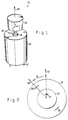
- FIG. 1 illustrates an embodiment of the invention in which there is shown a dual-spin stabilized device or body indicated generally at 20.
- a dual-spin stabilized device or body indicated generally at 20.
- a device is an orbiting satellite.
- the satellite 20 has a nominally despun platform 22 which is coupled to a nominally spun rotor 24 by means of a bearing assembly and despin motor 26.
- the "platform” 22 may be a body or member of any shape such as, for example, an antenna.
- the spin or pitch axis is illustrated by an arrow 25.
- the platform 22 is referred to as despun, it may be rotating with respect to the rotor 24.
- a relative spin phase or rate sensor 28 such as a shaft angle encoder is disposed on the satellite 20 and generates a signal in the form of successive index pulses indicative of the relative phase and rate of rotation of the rotor 24 with respect to the despun platform 22.
- the relative rate sensor 28 is comprised of a magnet 34 mounted on the despun platform 22 and sensing coils 35 and 36 disposed on the rotor 24.
- the relative rate sensor 28 may be found already installed on the satellite 20 as part of a despin attitude or pointing system or as part of a nutation control system which includes a separate nutation sensor such as an accelerometer or a horizon sensor. Where the present invention is used with a spin stabilized device which has a nutation control system including both a relative rate sensor and an accelerometer, the present invention will function as a back-up system in case of failure of the primary nutation sensor. Alternatively, the nutation control sensor and system of the present invention may be used in a stand-alone configuration.
- FIG. 3 there is shown a schematic diagram indicating the interconnection of the elements of the nutation control system of the present invention.
- nutation measurement and control processing are performed at a ground station 40 and are performed for the control of a dual-spin stabilized satellite.
- measurement and control functions can be performed on-board the satellite 20 with satellite electronics.
- the satellite 20 includes an antenna 30 mounted on the platform 22 for sending and receiving signals to and from the ground station 40 on the earth.
- the satellite 20 also includes at least one thruster 32 mounted on the rotor 24 for applying a torque to the satellite to damp nutation.
- the thruster 32 is one of a plurality of thrusters which are part of a satellite reaction control system.
- the nutation damping torque may be applied by appropriately timed activation of the despin motor 26 or other actuator capable of applying torques to the platform or rotor.
- the despin motor 26 is used to apply the nutation damping torques, relative spin phase information is not required and nutation sensing may be accomplished by detecting and processing only the relative spin rates of the rotor and platform.
- a telemetry and command subsystem 33 controls the sending of index pulses from the relative phase or rate sensor 28 through the antenna 30 and the receiving of commands from the ground station 40 for the thruster 32 or alternatively the despin motor 26.
- the ground station 40 includes an antenna 42 for receiving data signals from and sending control signals to the satellite 20.
- An index pulse discriminator 44 is coupled to the antenna 42 for separating out index pulses from other data signals.
- Other attitude data is received from the antenna 42 by an attitude parameter update system 45.
- the index pulses are provided to an index pulse arrive time circuit 46 which determines the relative time positions of successive index pulses.
- the circuit 46 output is coupled to a nutation measurement and control processor 48 which is described in more detail below with reference to FIG. 4.
- the nutation measurement and control processor 48 provides thruster execute pulses to a command generator 50 which is coupled to the ground station antenna 42. Thruster execute pulses are transmitted from the ground station antenna 42 to the satellite antenna 30 and relayed by the telemetry and command subsystem 33 to the thruster 32. Thruster execute commands are generated by the nutation measurement and control processor 48 when the nutation exceeds a predetermined threshold.
- nutation information is derived by the present invention, in conventional designs of dual-spin satellites, the principal axis of inertia of the rotor is aligned with the bearing axis which joins the rotor and payload platform.
- the rotor is further statically balanced so that its center of mass lies on the common bearing axis.
- the rotor principal axis, bearing axis, and angular momentum vector are all coaligned.
- Nutation is a transient displacement of the bearing axis from the angular momentum vector analytically manifested by a spin plane component of angular momentum or rate, and physically by a coning motion of the bearing axis about the angular momentum vector.
- the payload platform does not spin, it is not necessary that it be balanced. Indeed, for the present invention to work it must have a dynamic imbalance or product of inertia in a plane containing the bearing axis.
- Present day communication satellites naturally have such a product of inertia produced by large reflectors set to the anti-earth side of the satellite to achieve proper focal relationship with reflector feeds.
- Other payloads often produce, or are easily arranged to produce a similar product of inertia.
- platform spin is not precluded, i.e., the described nutation coupling remains under platform spin and the present invention works in the presence of moderate platform spin rates.
- the satellite transverse inertias I11 and I22, platform spin inertia I p and platform product of inertia I23 are all inherent to a given satellite and are determined prior to launch and updated when necessary as, for example, when fuel is used.
- the nutation transverse rates are ⁇ 1 and ⁇ 2.
- the subscripts 1, 2 and 3 refer to a platform fixed coordinate system shown in FIG. 1.
- the perturbation of the platform spin acceleration ⁇ 3 in equation (3) causes the oscillation or perturbation in the platform to rotor relative phase ⁇ .
- This relative phase oscillation causes an oscillation at nutation frequency ⁇ o , with a magnitude proportional to the nutation angle, in the relative time position of successive index pulses which are received from the relative spin phase sensor 28.
- the index pulse occurrence times are provided by the index pulse arrive time circuit 46 to the nutation measurement and control processor 48.
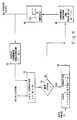
- a logic diagram is shown depicting the processing algorithm performed by the nutation measurement and control processor 48.
- a four state estimate of the spacecraft motion x is updated by a model of the spacecraft nutation dynamics at a computation cycle interrupt period.
- the state estimate x includes the rotor to platform relative phase ⁇ and relative rate ⁇ as well as the orthogonal platform angular rates of rotation ⁇ 1, ⁇ 2 in a plane normal to the spin axis 25.
- the state estimate x and any thruster torques are operated on by the system dynamics matrices A and B, respectively, to update the state estimate x.
- These system dynamics matrices are dependent on the mass properties and momentum of the satellite 20 and on the thruster geometry.
- a decision block 54 determines if a new index pulse has arrived since the last computation cycle interrupt. If there has been a new index pulse, a state correction block 56 corrects the state estimate x to incorporate the new data.
- the states representing the transverse angular rates of rotation ⁇ 1 and ⁇ 2 are the derived estimate of nutation.
- the estimated states, ⁇ 1, ⁇ 2 and in some cases ⁇ are used to operate actuators in a manner to damp vehicle nutation. In the preferred embodiment, this is done by thresholding a control signal generated from the state estimates.
- a modulation and phase delay block 58 establishes the proper phase for the control signal to be transmitted to the satellite 20.
- the phase delayed and coordinate transformed state estimate is then provided to a threshold block 60 which provides thruster pulse signals to the command generator 50 when the nutation exceeds a predetermined threshold.
- the thruster command signals are transmitted to the satellite 20 by the ground station antenna 42.
- an inverse coordinate transform block 62 receives the thruster pulses u and transforms the signals back into platform fixed coordinates.
- the transformations utilize the estimate ⁇ of the relative phase, ⁇ .
- the thruster pulse signals are then fed back into the system dynamics model at the state propagation block 52.
- the two coordinate transformations in the blocks 58 and 62 are not required.
Landscapes
- Engineering & Computer Science (AREA)
- Remote Sensing (AREA)
- Chemical & Material Sciences (AREA)
- Combustion & Propulsion (AREA)
- Radar, Positioning & Navigation (AREA)
- Aviation & Aerospace Engineering (AREA)
- Automation & Control Theory (AREA)
- Control Of Position, Course, Altitude, Or Attitude Of Moving Bodies (AREA)
- Navigation (AREA)
- Details Of Aerials (AREA)
Claims (15)
- Nutationssensor zur Verwendung in einer Dual-Spin-stabilisierten Vorrichtung (20), insbesondere in einem Dual-Spin-stabilisierten Satelliten, der einen nominell sich drehenden Rotor (24) und eine nominell entdrallte Plattform (22) aufweist, mit:
einem Sensor (23, 28) zum Messen der relativen Spinphase oder der relativen Spingeschwindigkeit zwischen dem nominell sich drehenden Rotor (24) und der nominell entdrallten Plattform (22) sowie zum Liefern von Signalen, die für die gemessene relative Spinphase oder relative Spingeschwindigkeit kennzeichnend sind;
Mitteln zum Detektieren der über der Zeit relativen Positionen von aufeinanderfolgenden der Signale; und
Mitteln zum Berechnen der Nutation der Vorrichtung (20) aus den über der Zeit relativen Positionen von aufeinanderfolgenden Signalen. - Nutationssensor nach Anspruch 1, dadurch gekennzeichnet, daß der Sensor (23, 28) ein Wellen-Winkelencoder (28) ist.
- Nutationssensor nach Anspruch 1 oder Anspruch 2, dadurch gekennzeichnet, daß die aufeinanderfolgenden Signale Index-Pulse sind.
- Nutationssensor nach Anspruch 3, dadurch gekennzeichnet, daß die Mittel zum Berechnen die Nutation der Dual-Spin-stabilisierten Vorrichtung (20) berechnen basierend auf durch Kopplung der Nutationsbewegung der Vorrichtung mit der Drehbewegung der nominell entdrallten Plattform (22) bewirkten sinusförmigen Störungen in den über der Zeit relativen Positionen der aufeinanderfolgenden Index-Pulse.
- Nutationskontrollsystem for eine Dual-Spin-stabilisierte Vorrichtung (20), wobei das System einen Nutationssensor gemaß einem der Ansprüche 1 bis 4 umfaßt und weiter Mittel aufweist, die auf die Ausgabe der Mittel zum Berechnen der Nutation der Vorrichtung (20) ansprechen, um ein Moment auf die Vorrichtung (20) auszuüben und ihre Nutation zu reduzieren.
- Nutationskontrollsystem nach Anspruch 5, dadurch gekennzeichnet, daß die ein Moment ausübenden Mittel wenigstens ein Triebwerk (32) umfassen, das an dem nominell sich drehenden Rotor (24) angeordnet ist.
- Nutationskontrollsystem nach Anspruch 6, dadurch gekennzeichnet, daß das wenigstens eine Triebwerk (32) gezündet wird, wenn die Nutation einen vorbestimmten Schwellenwert überschreitet.
- Nutationskontrollsystem nach einem der Ansprüche 5 bis 7, dadurch gekennzeichnet, daß die ein Moment ausübenden Mittel ein Motor (26) zum Stabilisieren sind.
- Nutationskontrollsystem nach einem der Ansprüche 5 bis 8, bei dem die Dual-Spin-stabilisierte Vorrichtung (20) ein Dual-Spin-stabilisierter Satellit ist, gekennzeichnet durch eine Bodenstation (40);
Mittel (30) zum Übertragen der Index-Pulse zu der Bodenstation (40);
Mittel (46) zum Detektieren der über der Zeit relativen Positionen der Index-Pulse, wobei die Mittel zum Detektieren (46) und die Mittel zum Berechnen bei der Bodenstation (40) angeordnet sind; und
Mittel (48, 50, 42), welche an den Ausgang der Mittel zum Berechnen gekoppelt sind, um Steuersignale von der Bodenstation (40) zu dem Dual-Spin-stabilisierten Satelliten zu übertragen und die ein Moment ausübenden Mittel zu steuern. - Nutationskontrollsystem nach Anspruch 9, dadurch gekennzeichnet, daß
die Mittel (30) zum Übertragen eine Abwärtsverbindungsantenne sind, welche Lagedaten des Satelliten einschließlich der Index-Pulse überträgt;
wobei die Bodenstation (40) umfaßt:
eine Empfangsantenne (42) zum Empfang der Lagedaten des Satelliten;
Mittel (44) zum Trennen der Index-Pulse von den Lagedaten des Satelliten;
Mittel (46) zum Messen der Ankunftszeiten der Index-Pulse;
Mittel (48) zum Berechnen der Nutation des Satelliten aus den gemessenen Ankunftszeiten der Index-Pulse;
Mittel (48, 50) zum Erzeugen von Steuersignalen zur Kompensation der Nutation;
eine Aufwärtsverbindungsantenne (42) zum Übertragen der Steuersignale zu dem Satelliten;
wobei der Satellit eine Satellitenempfangsantenne (30) zum Empfang der Steuersignale umfaßt. - Verfahren zur Messung der Nutation einer Dual-Spin-stabilisierten Vorrichtung (20), insbesondere eines Dual-Spin-stabilisierten Satelliten, der einen nominell sich drehenden Rotor (24) und eine nominell entdrallte Plattform (22) umfaßt, mit den Schritten:
Messen der relativen Spinphase oder relativen Spingeschwindigkeit zwischen dem nominell sich drehenden Rotor (24) und der nominell entdrallten Plattform (22);
Liefern von Signalen, die für die gemessene relative Spinphase oder relative Spingeschwindigkeit kennzeichnend sind;
Detektieren der über der Zeit relativen Positionen von aufeinanderfolgenden der Signale;
Berechnen der Nutation der Vorrichtung (20) aus den über der Zeit relativen Positionen von aufeinanderfolgenden Signalen. - Verfahren nach Anspruch 11, dadurch gekennzeichnet, daß der Schritt der Berechnung die durch die Kopplung der Nutationsbewegung der Vorrichtung mit der Spinbewegung der nominell entdrallten Plattform (22) bewirkten sinusförmigen Störungen in den über der Zeit relativen Positionen von aufeinanderfolgenden Signalen verwendet, um die Nutation der Dual-Spin-stabilisierten Vorrichtung (20) zu berechnen.
- Verfahren nach Anspruch 11 oder 12, dadurch gekennzeichnet, daß der Schritt des Lieferns der Signale den Schritt des Lieferns von Index-Pulsen umfaßt.
- Verfahren zum Steuern der Nutation einer Dual-Spin-stabilisierten Vorrichtung (20), insbesondere eines Dual-Spin-stabilisierten Satelliten, mit einem nominell sich drehenden Rotor (24) und einer nominell entdrallten Plattform (22), das das Verfahren nach einem der Ansprüche 11 bis 13 umfaßt und ferner den Schritt des Ausübens eines Momentes auf die Dual-Spin-stabilisierte Vorrichtung (20) umfaßt, um ihre Nutation zu reduzieren.
- Verfahren nach Anspruch 14, bei dem die Dual-Spin-stabilisierte Vorrichtung (20) ein Satellit ist, gekennzeichnet durch die weiteren Schritte:
Übertragen von Lagedaten des Satelliten einschließlich der Index-Pulse zu einer Bodenstation (40);
Empfangen der Lagedaten des Satelliten an der Bodenstation (40);
Trennen der Index-Pulse von den empfangenen Lagedaten des Satelliten;
Erzeugen von Steuersignalen zum Kompensieren der Nutation des Satelliten;
Übertragen der Steuersignale von der Bodenstation zu dem Satelliten; und
Empfangen der Steuersignale an dem Satelliten.
Applications Claiming Priority (2)
| Application Number | Priority Date | Filing Date | Title |
|---|---|---|---|
| US07/063,373 US4824052A (en) | 1987-06-18 | 1987-06-18 | Nutation sensor and nutation control system for a dual-spin stabilized satellite |
| US63373 | 2002-04-16 |
Publications (2)
| Publication Number | Publication Date |
|---|---|
| EP0321513A1 EP0321513A1 (de) | 1989-06-28 |
| EP0321513B1 true EP0321513B1 (de) | 1993-12-29 |
Family
ID=22048760
Family Applications (1)
| Application Number | Title | Priority Date | Filing Date |
|---|---|---|---|
| EP88904838A Expired - Lifetime EP0321513B1 (de) | 1987-06-18 | 1988-05-06 | Nutationsensor und nutationsteuerungssystem für einen stabilisierten doppelspinsatellit |
Country Status (6)
| Country | Link |
|---|---|
| US (1) | US4824052A (de) |
| EP (1) | EP0321513B1 (de) |
| JP (1) | JPH02500662A (de) |
| CA (1) | CA1325666C (de) |
| DE (1) | DE3886714T2 (de) |
| WO (1) | WO1988010459A1 (de) |
Families Citing this family (9)
| Publication number | Priority date | Publication date | Assignee | Title |
|---|---|---|---|---|
| FR2630354B1 (fr) * | 1988-04-20 | 1990-08-31 | Mecanique Magnetique Sa | Dispositif vibrateur actif a suspension magnetique asservie selon trois axes |
| FR2642552B1 (de) * | 1989-01-31 | 1991-05-24 | Europ Propulsion | |
| FR2642538B1 (fr) * | 1989-01-31 | 1991-05-24 | Europ Propulsion | Systeme de stabilisation mecanique a contre-rotation a rotors emboites |
| US5067673A (en) * | 1990-02-07 | 1991-11-26 | Hughes Aircraft Company | Essentially passive method for inverting the orientation of a dual spin spacecraft |
| US5308025A (en) * | 1992-07-30 | 1994-05-03 | Hughes Aircraft Company | Spacecraft spin axis capture system and method |
| US5816538A (en) * | 1994-10-13 | 1998-10-06 | Hughes Electronics Corporation | Dynamic decoupler for improved attitude control |
| US6463365B1 (en) * | 2000-02-01 | 2002-10-08 | Raytheon Company | System and method for controlling the attitude of a space craft |
| US7090171B2 (en) | 2003-01-14 | 2006-08-15 | Honeywell International, Inc. | Momentum stabilized launch vehicle upper stage |
| IT201900012498A1 (it) * | 2019-07-22 | 2021-01-22 | D Orbit S P A | Modulo satellitare per la determinazione di assetto |
Family Cites Families (12)
| Publication number | Priority date | Publication date | Assignee | Title |
|---|---|---|---|---|
| US3714434A (en) * | 1967-07-31 | 1973-01-30 | Hughes Aircraft Co | Despin control system for a multispin stabilized device |
| GB1220626A (en) * | 1967-07-31 | 1971-01-27 | Hughes Aircraft Co | Despin control system |
| US3830447A (en) * | 1972-09-28 | 1974-08-20 | Rca Corp | Active nutation damping in dual-spin spacecraft |
| US3996804A (en) * | 1975-02-19 | 1976-12-14 | Hughes Aircraft Company | Method for remotely determining the dynamic imbalance of and for changing the spin rate and center of gravity of a spinning body |
| US4096427A (en) * | 1975-10-21 | 1978-06-20 | Hughes Aircraft Company | Nutation damping in dual-spin stabilized devices |
| US4275861A (en) * | 1978-08-04 | 1981-06-30 | Rca Corporation | Orientation of momentum stabilized vehicles |
| US4272045A (en) * | 1979-03-29 | 1981-06-09 | Rca Corporation | Nutation damping in a dual-spin spacecraft |
| US4437047A (en) * | 1981-07-13 | 1984-03-13 | Hughes Aircraft Company | System for autonomous earth-pointing acquisition of a dual-spin satellite |
| DE3482789D1 (de) * | 1983-03-12 | 1990-08-30 | British Aerospace | Nutations-daempfung. |
| WO1986000863A1 (en) * | 1984-07-20 | 1986-02-13 | Hughes Aircraft Company | Spin-stabilized satellite with nutation control subsystem |
| US4752884A (en) * | 1985-07-18 | 1988-06-21 | Hughes Aircraft Company | Precision platform pointing controller for a dual-spin spacecraft |
| EP0231273B1 (de) * | 1985-07-18 | 1990-09-19 | Hughes Aircraft Company | Selbständige lageänderung der spinachse eines drallstabilisierten raumfahrzeuges |
-
1987
- 1987-06-18 US US07/063,373 patent/US4824052A/en not_active Expired - Lifetime
-
1988
- 1988-05-06 WO PCT/US1988/001465 patent/WO1988010459A1/en not_active Ceased
- 1988-05-06 DE DE3886714T patent/DE3886714T2/de not_active Expired - Fee Related
- 1988-05-06 JP JP63504565A patent/JPH02500662A/ja active Pending
- 1988-05-06 EP EP88904838A patent/EP0321513B1/de not_active Expired - Lifetime
- 1988-06-17 CA CA000569799A patent/CA1325666C/en not_active Expired - Fee Related
Non-Patent Citations (1)
| Title |
|---|
| NEC - Research & Development, no. 83, 1986, (Tokyo, JP) K. Ninomiya et al. : "Development of the microprocessor-based attitude control system for ASTRO-C",pages 76-81,see page 77,right-hand column,line 15-page 79,left-hand column,line 18 * |
Also Published As
| Publication number | Publication date |
|---|---|
| DE3886714D1 (de) | 1994-02-10 |
| JPH02500662A (ja) | 1990-03-08 |
| US4824052A (en) | 1989-04-25 |
| WO1988010459A1 (en) | 1988-12-29 |
| CA1325666C (en) | 1993-12-28 |
| DE3886714T2 (de) | 1994-07-14 |
| EP0321513A1 (de) | 1989-06-28 |
Similar Documents
| Publication | Publication Date | Title |
|---|---|---|
| EP0453096B1 (de) | Vorrichtung zur Steuerung der Lage eines Satelliten in einer geneigten Umlaufbahn | |
| EP0743249B1 (de) | Universelles Lageregelungssystem für Raumfahrzeug | |
| US5558305A (en) | Measuring arrangement useful for controlling the attitude of a three-axis stabilized satellite, corresponding evaluation process, regulating system and process | |
| EP0148550B1 (de) | Methode und Vorrichtung zur Triebwerksausgleichssteuerung | |
| EP0568209B1 (de) | Lageregelung und Momentenausgleich für Raumfahrzeuge mittels kardanisch befestigten und kontinuierlich gedrosselten Triebwerken | |
| US5765780A (en) | Systematic vectored thrust calibration method for satellite momentum control | |
| US6296207B1 (en) | Combined stationkeeping and momentum management | |
| JP2625286B2 (ja) | モーメントバイアスされた宇宙船用の姿勢制御システム | |
| EP0739818B1 (de) | Satelliten Drallstabilisationsverfahren, in dem ein transversales Trägheitsmoment mit einem einzigen Freiheitsgrad gespeichert wird, und System dazu | |
| US5441222A (en) | Attitude control of spinning spacecraft | |
| EP0322349A2 (de) | System zur Bestimmung und Steuerung der Lage eines Satelliten mit einem in Richtung steuerbaren Sensorsbündel | |
| EP3854698B1 (de) | Ausrichtungssteuerungsvorrichtung, satellit, ausrichtungssteuerungsverfahren und programm | |
| JPS6047159B2 (ja) | 衛星の姿勢制御装置 | |
| US8620496B2 (en) | Systems and method of controlling a spacecraft using attitude sensors | |
| US6360996B1 (en) | Steering control for skewed scissors pair CMG clusters | |
| US6263264B1 (en) | Pseudo gyro with unmodeled disturbance torque estimation | |
| EP0321513B1 (de) | Nutationsensor und nutationsteuerungssystem für einen stabilisierten doppelspinsatellit | |
| US20050071055A1 (en) | Refinement of spacecraft angular velocity and attitude estimates using star data | |
| US3830447A (en) | Active nutation damping in dual-spin spacecraft | |
| US6354163B1 (en) | Mitigating gimbal induced disturbances in CMG arrays | |
| US4023752A (en) | Elimination of residual spacecraft nutation due to propulsive torques | |
| EP0544241A1 (de) | Methode und Vorrichtung zur dynamischen Prekompensation von Rückwirkungen der Schrittbewegung eines Solarpaneels auf einen Satelliten | |
| USRE30429E (en) | Minimization of residual spacecraft nutation due to disturbing torques | |
| Aslanov et al. | The motion of coaxial bodies of varying composition on the active leg of descent | |
| Vaeth | Flywheel control of space vehicles |
Legal Events
| Date | Code | Title | Description |
|---|---|---|---|
| PUAI | Public reference made under article 153(3) epc to a published international application that has entered the european phase |
Free format text: ORIGINAL CODE: 0009012 |
|
| 17P | Request for examination filed |
Effective date: 19890208 |
|
| AK | Designated contracting states |
Kind code of ref document: A1 Designated state(s): DE FR GB IT |
|
| 17Q | First examination report despatched |
Effective date: 19910821 |
|
| GRAA | (expected) grant |
Free format text: ORIGINAL CODE: 0009210 |
|
| AK | Designated contracting states |
Kind code of ref document: B1 Designated state(s): DE FR GB IT |
|
| ITF | It: translation for a ep patent filed | ||
| REF | Corresponds to: |
Ref document number: 3886714 Country of ref document: DE Date of ref document: 19940210 |
|
| ET | Fr: translation filed | ||
| PLBE | No opposition filed within time limit |
Free format text: ORIGINAL CODE: 0009261 |
|
| STAA | Information on the status of an ep patent application or granted ep patent |
Free format text: STATUS: NO OPPOSITION FILED WITHIN TIME LIMIT |
|
| 26N | No opposition filed | ||
| PGFP | Annual fee paid to national office [announced via postgrant information from national office to epo] |
Ref country code: FR Payment date: 19950410 Year of fee payment: 8 |
|
| PGFP | Annual fee paid to national office [announced via postgrant information from national office to epo] |
Ref country code: GB Payment date: 19950413 Year of fee payment: 8 |
|
| PGFP | Annual fee paid to national office [announced via postgrant information from national office to epo] |
Ref country code: DE Payment date: 19950421 Year of fee payment: 8 |
|
| PG25 | Lapsed in a contracting state [announced via postgrant information from national office to epo] |
Ref country code: GB Effective date: 19960506 |
|
| GBPC | Gb: european patent ceased through non-payment of renewal fee |
Effective date: 19960506 |
|
| PG25 | Lapsed in a contracting state [announced via postgrant information from national office to epo] |
Ref country code: FR Effective date: 19970131 |
|
| PG25 | Lapsed in a contracting state [announced via postgrant information from national office to epo] |
Ref country code: DE Effective date: 19970201 |
|
| REG | Reference to a national code |
Ref country code: FR Ref legal event code: ST |
|
| PG25 | Lapsed in a contracting state [announced via postgrant information from national office to epo] |
Ref country code: IT Free format text: LAPSE BECAUSE OF NON-PAYMENT OF DUE FEES Effective date: 20050506 |