EP0321646A2 - Electric motor of a centrifugal pump - Google Patents
Electric motor of a centrifugal pump Download PDFInfo
- Publication number
- EP0321646A2 EP0321646A2 EP88111465A EP88111465A EP0321646A2 EP 0321646 A2 EP0321646 A2 EP 0321646A2 EP 88111465 A EP88111465 A EP 88111465A EP 88111465 A EP88111465 A EP 88111465A EP 0321646 A2 EP0321646 A2 EP 0321646A2
- Authority
- EP
- European Patent Office
- Prior art keywords
- electric motor
- contact block
- selector plug
- contacts
- plug
- Prior art date
- Legal status (The legal status is an assumption and is not a legal conclusion. Google has not performed a legal analysis and makes no representation as to the accuracy of the status listed.)
- Granted
Links
Images
Classifications
-
- H—ELECTRICITY
- H02—GENERATION; CONVERSION OR DISTRIBUTION OF ELECTRIC POWER
- H02K—DYNAMO-ELECTRIC MACHINES
- H02K17/00—Asynchronous induction motors; Asynchronous induction generators
- H02K17/02—Asynchronous induction motors
- H02K17/30—Structural association of asynchronous induction motors with auxiliary electric devices influencing the characteristics of the motor or controlling the motor, e.g. with impedances or switches
-
- H—ELECTRICITY
- H02—GENERATION; CONVERSION OR DISTRIBUTION OF ELECTRIC POWER
- H02K—DYNAMO-ELECTRIC MACHINES
- H02K5/00—Casings; Enclosures; Supports
- H02K5/04—Casings or enclosures characterised by the shape, form or construction thereof
- H02K5/22—Auxiliary parts of casings not covered by groups H02K5/06-H02K5/20, e.g. shaped to form connection boxes or terminal boxes
- H02K5/225—Terminal boxes or connection arrangements
-
- H—ELECTRICITY
- H02—GENERATION; CONVERSION OR DISTRIBUTION OF ELECTRIC POWER
- H02K—DYNAMO-ELECTRIC MACHINES
- H02K2211/00—Specific aspects not provided for in the other groups of this subclass relating to measuring or protective devices or electric components
- H02K2211/03—Machines characterised by circuit boards, e.g. pcb
Definitions
- the invention relates to an electric motor of a centrifugal pump with a contact block, in particular fastened to the winding head or motor housing, to the contacts of which the winding wire ends are fastened, wherein a selector plug is provided, through whose different insertion positions the desired speed and / or the desired voltage can be selected.
- Such an electric motor is known from DE-OS 34 35 289.
- this known motor there are numerous contacts, lines and parts between the selector plug and the winding wires of the winding head in order to make connections. This is complex to manufacture and the cause of sources of error.
- the object of the invention is to provide an electric motor Improve the type mentioned so that manufacture, assembly and use are simplified and the number of contacts are reduced.
- This object is achieved in that the selector plug is plugged directly into the contact block.
- Such an electric motor has the following advantages: - a drastic reduction in the number of contacts required, - direct contact of the winding wires with the changeover contacts, - Standard motors can be delivered without a terminal box, - different plug systems can be used and exchanged by the customer, - the motor can be changed without changing the terminal box or even opening it, - a clear separation from the hot engine compartment to the terminal box, - no unnecessary terminal box in automatic mode.
- This also creates a user interface that enables the user to make changes in the connection system themselves in a simple manner. Be it changing the speed or removing the control box when changing the motor or attaching a connector for automatic switching devices.
- the selector plug extend through the housing wall of the motor. It is particularly advantageous if the selector plug is seated on the outside of the motor housing and its contacts extend through the housing wall of the motor to the contacts of the contact block. Alternatively, the selector plug can also be used sit on a line board or another electrical line element located outside the motor housing and its contacts extend through the circuit board and through the housing wall of the motor to the contacts of the contact block. The board can also be attached in or on the terminal box.
- a carrier plate is fastened to the outside of the motor housing, on which the terminal box is fastened or which forms the terminal box and through which the selector plug extends. It is also advantageous that a connector for automatic switching devices can be attached to the contact block.
- the electric motor of a centrifugal pump has a housing wall 1, within which the rotor, not shown, and the stator 2 are arranged together with the end winding head 3.
- a contact block 4 according to the embodiment shown in FIG. 1 is attached within the housing 1.
- the contact block 4 can be attached directly to the winding head 3 or, corresponding to FIG. 1, on the underside of the upper region of the housing wall 1. In this case, it is attached according to FIG , wherein the flange-like upper edge 7 of the holding part 5 overlaps the edge of the opening 6 on the outside.
- the holding part 5 thus forms an upwardly open insertion opening 8 into which a selector plug 9 can be inserted from above.
- the selector plug 9 has a projecting collar 10 in the upper area, which comes to rest on the edge 7 at the top.
- the contact block 4 has openings 13 on its upper side, which lead to contact springs 14.
- the winding wires of the winding head 3 are electrically connected to these contact springs 14. These openings 13 coincide with the contact pins 14 protruding from the bottom of the selector plug 9, so that when the selector plug 9 is inserted, the contact pins 15 penetrate into the contact springs 14.
- the selector plug 9 can be inserted in different rotational positions from above, so that contact pins 15 reach different contact springs 14. As a result, different speeds and / or voltages can be generated in a known manner.
- the housing of a terminal box 16 is formed on the holding part 5 on the side facing the pump.
- This terminal box carries a circuit board 17 with electrical components, e.g. also for the external motor connection.
- the circuit board 17 is connected to the contact springs 14 via contact pins 20 projecting downward through the floor, a spring bridge 21 being fastened for this connection in the interior of the contact block 4.
- the contact block 4 can be supported by holding parts attached to the stator or housing, in particular an angle 22, in particular from below. Furthermore, there is a sealing ring 23 below the edge 7, which surrounds the opening 6 all around at the top and prevents penetration of moisture and dust into the interior of the housing.
- the embodiment according to FIG. 2 differs from that according to FIG. 1 in that the holding part lying on the outside on top of the housing wall 1 is designed essentially only as a plate 5a which is fastened to the housing 1 and which in turn carries or forms the terminal box 16 .
- the cube-shaped selector plug 9 lies on the top of the horizontal top of the holding part 5a with its collar 10 sealingly, and only the contact pins 15 extend vertically downward through individual vertical bores similar openings 24 and protrude beyond the underside of the holding part 5a in order to Penetrating openings 13 of the contact block 4 and there to reach the contact springs 14.
- an edge 25 projects vertically, which forms a cavity which is open at the bottom and in which the upper region of the contact block 4 lies so that the contact block 4 is surrounded by the edge 25.
- the contact block 4 can be attached directly to the winding head 3 in both exemplary embodiments.
- connection techniques in particular the clamping-cutting technique, can be used to fasten the winding wires to the contact springs 14.
- the circuit board 17 projects beyond the terminal box 16 and is embedded above the contact block 4 in the material of the holding part 5a, the board 17 having openings which match the openings 24.
- contact elements in particular contact springs, protrude into the openings 24, which are connected to lines of the board 17 and which additionally contact the contact pins 15 of the selector plug 9.
- the holding part 5b is formed by a relatively small horizontal plate which only surrounds the opening 6 and in turn has an opening 8 through which the selector plug 9 reaches the contact block 4.
- a connecting plug 26 in particular an automatic plug, can also be inserted through the opening of the holding part 5b, as shown in FIG. 3, which in the same way reaches the contact springs 14 of the contact block 4 with contact pins 27.
- at least the lower area of the plug 26 is of the same dimensions as the selector plug 9. Via such a plug 26, current can be supplied to the motor, among other things, and it can also be connected to a switch box via a cable 28.
- the automatic connector 26 and the holding part 5b can also be made in one piece.
Landscapes
- Engineering & Computer Science (AREA)
- Power Engineering (AREA)
- Structures Of Non-Positive Displacement Pumps (AREA)
- Motor Or Generator Frames (AREA)
Abstract
Die Erfindung betrifft einen Elektromotor einer Kreiselpumpe mit einem insbesondere am Wicklungskopf oder Motorengehäuse befestigten Kontaktblock, an dessen Kontakte die Wicklungsdrahtenden befestigt sind, wobei eine Wahlstecker vorgesehen ist, durch dessen unterschiedliche Einsteckstellungen die gewünschte Drehzahl und/oder die gewünschte Spannung wählbar ist. Der Wahlstecker (9) ist unmittelbar am Kontaktblock (4) angesteckt. 
Description
Die Erfindung betrifft einen Elektromotor einer Kreiselpumpe mit einem insbesondere am Wicklungskopf oder Motorengehäuse befestigten Kontaktblock, an dessen Kontakte die Wicklungsdrahtenden befestigt sind, wobei ein Wahlstecker vorgesehen ist, durch dessen unterschiedliche Einsteckstellungen die gewünschte Drehzahl und/oder die gewünschte Spannung wählbar ist.The invention relates to an electric motor of a centrifugal pump with a contact block, in particular fastened to the winding head or motor housing, to the contacts of which the winding wire ends are fastened, wherein a selector plug is provided, through whose different insertion positions the desired speed and / or the desired voltage can be selected.
Aus der DE-OS 34 35 289 ist ein solcher Elektromotor bekannt. Bei diesem bekannten Motor sind zwischen Wahlstecker und Wicklungsdrähten des Wicklungskopfes zahlreiche Kontakte, Leitungen und Teile, um Verbindungen herzustellen. Dies ist in der Herstellung aufwendig und Ursache von Fehlerquellen.Such an electric motor is known from DE-OS 34 35 289. In this known motor there are numerous contacts, lines and parts between the selector plug and the winding wires of the winding head in order to make connections. This is complex to manufacture and the cause of sources of error.
Aufgabe der Erfindung ist es, einen Elektromotor der eingangs genannten Art so zu verbessern, daß Herstellung, Montage und Nutzung vereinfacht und die Zahl der Kontakte reduziert sind.The object of the invention is to provide an electric motor Improve the type mentioned so that manufacture, assembly and use are simplified and the number of contacts are reduced.
Diese Aufgabe wird erfindungsgemäß dadurch gelöst, daß der Wahlstecker unmittelbar am Kontaktblock angesteckt ist.This object is achieved in that the selector plug is plugged directly into the contact block.
Ein solcher Elektromotor weist folgende Vorteile auf:
- eine drastische Reduzierung der erforderlichen Kontakte,
- ein direktes Anschlagen der Wickeldrähte an die Umschaltkontakte,
- ein Ausliefern von Standardmotoren ist ohne Klemmenkasten möglich,
- verschiedene Stecksysteme sind vom Kunden anwendbar und wechselbar,
- der Motorwechsel ist möglich, ohne den Klemmenkasten mit zu wechseln oder auch nur zu öffnen,
- eine eindeutige Trennung vom heißen Motorenraum zum Klemmenkasten,
- bei Automatikbetrieb kein überflüssiger Klemmenkasten.
Damit ist auch eine Benutzerschnittstelle geschaffen, die es dem Anwender ermöglicht, Veränderungen im Anschlußsystem selber auf einfache Weise vorzunehmen. Sei es das Verändern der Drehzahl oder das Abnehmen des Schaltkastens beim Motorwechsel oder auch das Anbringen eines Anschlußsteckers für Automatik-Schaltgeräte.Such an electric motor has the following advantages:
- a drastic reduction in the number of contacts required,
- direct contact of the winding wires with the changeover contacts,
- Standard motors can be delivered without a terminal box,
- different plug systems can be used and exchanged by the customer,
- the motor can be changed without changing the terminal box or even opening it,
- a clear separation from the hot engine compartment to the terminal box,
- no unnecessary terminal box in automatic mode.
This also creates a user interface that enables the user to make changes in the connection system themselves in a simple manner. Be it changing the speed or removing the control box when changing the motor or attaching a connector for automatic switching devices.
Vorzugsweise wird vorgeschlagen, daß der Wahlstecker durch die Gehäusewand des Motors hindurchreicht. Besonders vorteilhaft ist es, wenn der Wahlstecker außen auf dem Motorengehäuse aufsitzt und seine Kontakte durch die Gehäusewand des Motors hindurchreichen bis zu den Kontakten des Kontaktblocks. Alternativ kann aber auch der Wahlstecker auf einer außerhalb des Motorengehäuses befindlichen Leitungsplatine oder einem anderen elektrischen Leitungselement aufsitzen und seine Kontakte durch die Platine und durch die Gehäusewand des Motors hindurchreichen bis zu den Kontakten des Kontaktblocks. Hierbei kann die Platine zusätzlich im oder am Klemmenkasten befestigt sein.It is preferably proposed that the selector plug extend through the housing wall of the motor. It is particularly advantageous if the selector plug is seated on the outside of the motor housing and its contacts extend through the housing wall of the motor to the contacts of the contact block. Alternatively, the selector plug can also be used sit on a line board or another electrical line element located outside the motor housing and its contacts extend through the circuit board and through the housing wall of the motor to the contacts of the contact block. The board can also be attached in or on the terminal box.
Besonders vorteilhaft ist es, wenn außen am Motorengehäuse eine Trägerplatte befestigt ist, auf der der Klemmenkasten befestigt ist oder die den Klemmenkasten bildet und durch die der Wahlstecker hindurchreicht. Auch ist von Vorteil, daß an dem Kontaktblock wahlweise ein Anschlußstecker für Automatik-Schaltgeräte befestigbar ist.It is particularly advantageous if a carrier plate is fastened to the outside of the motor housing, on which the terminal box is fastened or which forms the terminal box and through which the selector plug extends. It is also advantageous that a connector for automatic switching devices can be attached to the contact block.
Zwei Ausführungsbeispiele der Erfindung sind in den Zeichnungen dargestellt und werden im folgenden näher beschrieben. Es zeigen:
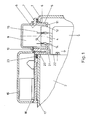
- Fig. 1 einen senkrechten Längsschnitt durch den oberen Bereich eines Elektromotors einer Pumpe mit einem durch eine Öffnung der Gehäusewand reichenden Wahlstecker;
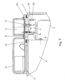
- Fig. 2 einen Schnitt nach Fig. 1 mit einem außen aufsitzenden Wahlstecker, dessen Kontaktstifte durch die Gehäusewand und durch die Leitungsplatine hindurchreichen;
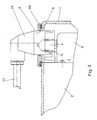
- Fig. 3 einen Schnitt nach Fig. 1 mit abgenommenem Wahlstecker und abgenommenem Klemmenkasten und statt dessen aufgestecktem Anschluß (Automatik)-Stecker.
- 1 shows a vertical longitudinal section through the upper region of an electric motor of a pump with a selector plug reaching through an opening in the housing wall;
- 2 shows a section according to FIG. 1 with an external selector plug, the contact pins of which extend through the housing wall and through the circuit board;
- Fig. 3 shows a section according to Fig. 1 with the selector plug and the terminal box removed and instead the plug (automatic) plug.
Der Elektromotor einer Kreiselpumpe weist eine Gehäusewand 1 auf, innerhalb derer der nicht dargestellte Rotor und der Stator 2 zusammen mit dem stirnseitigen Wicklungskopf 3 angeordnet ist. An der Oberseite des Wicklungskopfes 3 ist ein Kontaktblock 4 nach dem Ausführungsbeispiel entsprechend Fig. 1 innerhalb des Gehäuses 1 befestigt. Der Kontaktblock 4 kann direkt am Wicklungskopf 3 befestigt sein oder entrsprechend Fig. 1 an der Unterseite des oberen Bereiches der Gehäusewand 1. Hierbei ist er entsprechend Fig. 1 an der Unterseite eines Halteteils 5 befestigt, das topfförmig durch eine obere Öffnung 6 nach innen hindurchreicht, wobei der flanschähnliche obere Rand 7 des Halteteils 5 den Rand der Öffnung 6 außen übergreift. Das Halteteil 5 bildet damit eine nach oben hin offene Einstecköffnung 8, in der ein Wahlstecker 9 von oben einschiebbar ist. Hierbei besitzt der Wahlstecker 9 im oberen Bereich rundum einen vorspringenden Kragen 10, der oben auf dem Rand 7 zur Auflage kommt.The electric motor of a centrifugal pump has a housing wall 1, within which the rotor, not shown, and the
Im Boden 11 des Halteteils 5 befindet sich eine Öffnung 12, durch die von unten ein Bereich des Kontaktblockes 4 hindurchgesteckt ist. Der Kontaktblock 4 weist an seiner Oberseite Öffnungen 13 auf, die zu Kontaktfedern 14 führen. An diesen Kontaktfedern 14 sind die Wicklungsdrähte des Wicklungskopfes 3 elektrisch angeschlossen. Diese Öffnungen 13 stimmen mit den unten aus dem Wahlstecker 9 herausragenden Kontaktstiften 14 überein, so daß beim Einstecken des Wahlsteckers 9 die Kontaktstifte 15 in die Kontaktfedern 14 eindringen.In the
Der Wahlstecker 9 kann in unterschiedlichen Drehstellungen von oben eingesteckt werden, so daß Kontaktstifte 15 unterschiedliche Kontaktfedern 14 erreichen. Hierdurch können in bekannter Weise unterschiedliche Drehzahlen und/oder Spannnungen erzeugt werden.The
An dem Halteteil 5 ist auf der der Pumpe zugewandten Seite das Gehäuse eines Klemmenkastens 16 angeformt. Dieser Klemmenkasten trägt innen auf seinem Boden eine Leitungsplatine 17 mit elektrischen Bauteilen, z.B. auch für den externen Motoranschluß. Die Leitungsplatine 17 ist über nach unten durch den Boden hindurchragende Kontaktstifte 20 mit den Kontaktfedern 14 verbunden, wobei für diese Verbindung im Innern des Kontaktblocks 4 eine Federbrücke 21 befestigt ist.The housing of a
Der Kontaktblock 4 kann durch am Stator oder Gehäuse befestigte Halteteile, insbesondere einen Winkel 22 insbesondere von unten gestützt sein. Ferner befindet sich unterhalb des Randes 7 ein Dichtring 23, der die Öffnung 6 oben rundum umgibt und ein Eindringen von Feuchtigkeit und Staub in das Gehäuseinnere verhindert.The
Das Ausführungsbeispiel nach Fig. 2 unterscheidet sich von dem nach Fig. 1 dadurch, daß das außen oben auf der Gehäusewand 1 aufliegende Halteteil im wesentlichen nur als Platte 5a ausgeführt ist, die am Gehäuse 1 befestigt ist und die wiederum den Klemmenkasten 16 trägt oder bildet. Der würfelförmige Wahlstecker 9 liegt oben auf der waagerechten Oberseite des Halteteils 5a mit seinem Kragen 10 abdichtend auf, und nur die Kontaktstifte 15 reichen senkrecht nach unten durch einzelne senkrechte Bohrungen ähnliche Öffnungen 24 hindurch und ragen über die Unterseite des Halteteils 5a hinaus, um in die Öffnungen 13 des Kontaktblockes 4 einzudringen und dort die Kontaktfedern 14 zu erreichen.The embodiment according to FIG. 2 differs from that according to FIG. 1 in that the holding part lying on the outside on top of the housing wall 1 is designed essentially only as a
An der Unterseite des Halteteils 5 springt senkrecht ein Rand 25 vor, der einen nach unten hin offenen Hohlraum bildet, in dem der obere Bereich des Kontaktblockes 4 einliegt, so daß der Kontaktblock 4 vom Rand 25 umfaßt ist. In einer nicht dargestellten weiteren Alternative kann bei beiden Ausführungsbeispielen der Kontaktblock 4 direkt am Wicklungskopf 3 befestigt sein. Zur Befestigung der Wickeldrähte an den Kontaktfedern 14 können verschiedenste Verbindungstechniken, inbesondere die Klemm-Schneid-Technik verwendet werden.On the underside of the
Die Leitungsplatine 17 ragt im Ausführungsbeispiel nach Fig. 2 über den Klemmenkasten 16 hinaus und ist oberhalb des Kontaktblocks 4 im Material des Halteteils 5a eingebettet, wobei die Platine 17 mit den Öffnungen 24 übereinstimmende Öffnungen besitzt. An der Unter- oder Oberseite der Platine 17 ragen Kontaktelemente, insbesondere Kontaktfedern in die Öffnungen 24 hinein, die mit Leitungen der Platine 17 verbunden sind und die sich zusätzlich an die Kontaktstifte 15 des Wahlsteckers 9 anlegen. Damit kann auf einfachste Weise eine elektrische Verbindung zwischen Kontaktblock, Klemmenkasten und/oder Wahlstecker 9 erreicht werden.In the exemplary embodiment according to FIG. 2, the
Beim Ausführungsbeispiel nach Fig. 3 ist das Halteteil 5b von einer verhältnismäßig kleinen waagerechten Platte gebildet, die nur die Öffnung 6 umgibt und wiederum selber eine Öffnung 8 aufweist, durch die der Wahlstecker 9 den Kontaktblock 4 erreicht. Statt eines Wahlsteckers kann aber auch, wie in Fig. 3 gezeigt, durch die Öffnung des Halteteils 5b ein Anschlußstecker 26, insbesondere ein Automatikstecker, gesteckt werden, der in gleicher Weise mit Kontaktstiften 27 die Kontaktfedern 14 des Kontaktblockes 4 erreicht. Hierzu ist zumindest der untere Bereich des Steckers 26 in seinen Abmessungen gleich ausgeführt wie der Wahlstecker 9. Über einen solchen Stecker 26 kann u.a. dem Motor Strom zugeführt werden, und es kann ferner eine Verbindung zu einem Schaltkasten über ein Kabel 28 geschaffen werden.In the exemplary embodiment according to FIG. 3, the
In einem nicht dargestellten Ausführungsbeispiel kann der Automatikstecker 26 und das Halteteil 5b auch einteilig ausgeführt sein.In an embodiment not shown, the
Claims (8)
Priority Applications (1)
| Application Number | Priority Date | Filing Date | Title |
|---|---|---|---|
| AT88111465T ATE82446T1 (en) | 1987-12-19 | 1988-07-16 | ELECTRIC MOTOR OF A CENTRIFUGAL PUMP. |
Applications Claiming Priority (2)
| Application Number | Priority Date | Filing Date | Title |
|---|---|---|---|
| DE19873743168 DE3743168A1 (en) | 1987-12-19 | 1987-12-19 | ELECTRIC MOTOR OF A CENTRIFUGAL PUMP |
| DE3743168 | 1987-12-19 |
Publications (3)
| Publication Number | Publication Date |
|---|---|
| EP0321646A2 true EP0321646A2 (en) | 1989-06-28 |
| EP0321646A3 EP0321646A3 (en) | 1990-02-07 |
| EP0321646B1 EP0321646B1 (en) | 1992-11-11 |
Family
ID=6343026
Family Applications (1)
| Application Number | Title | Priority Date | Filing Date |
|---|---|---|---|
| EP19880111465 Expired - Lifetime EP0321646B1 (en) | 1987-12-19 | 1988-07-16 | Electric motor of a centrifugal pump |
Country Status (5)
| Country | Link |
|---|---|
| EP (1) | EP0321646B1 (en) |
| AT (1) | ATE82446T1 (en) |
| DE (2) | DE3743168A1 (en) |
| ES (1) | ES2035178T3 (en) |
| GR (1) | GR3006465T3 (en) |
Cited By (3)
| Publication number | Priority date | Publication date | Assignee | Title |
|---|---|---|---|---|
| EP0555720A1 (en) * | 1992-02-14 | 1993-08-18 | Siemens Aktiengesellschaft | Electric machine |
| EP0765024A1 (en) * | 1995-09-19 | 1997-03-26 | ELCO S.p.A. | Electric motor equipped for connection to a cable provided with a connector |
| WO2000046900A1 (en) * | 1999-02-06 | 2000-08-10 | Zf Lenksysteme Gmbh | Electric connector system for electric motors |
Families Citing this family (2)
| Publication number | Priority date | Publication date | Assignee | Title |
|---|---|---|---|---|
| DE19615706A1 (en) * | 1996-04-22 | 1997-10-23 | Teves Gmbh Alfred | Aggregate |
| DE10005505B4 (en) * | 2000-02-08 | 2019-03-28 | Grundfos A/S | heat pump |
Family Cites Families (8)
| Publication number | Priority date | Publication date | Assignee | Title |
|---|---|---|---|---|
| US2922054A (en) * | 1957-06-06 | 1960-01-19 | Miller Maurice | Motor wiring connector |
| GB2064230A (en) * | 1979-11-14 | 1981-06-10 | Sealed Motor Const Co Ltd | Electric motor construction |
| FR2498381A1 (en) * | 1981-01-16 | 1982-07-23 | Thomson Brandt | ELECTRIC MOTOR, CONNECTION ATTACHMENT FOR SUCH AN ENGINE, AND APPARATUS COMPRISING SAID ENGINE |
| JPS5819137A (en) * | 1981-07-24 | 1983-02-04 | Hitachi Ltd | 2-voltage specification type rotary electric machine |
| DE3435289A1 (en) * | 1984-09-26 | 1986-04-03 | Wilo-Werk Gmbh & Co Pumpen- Und Apparatebau, 4600 Dortmund | Connecting box for a pump motor |
| DE3445137A1 (en) * | 1984-12-11 | 1986-06-19 | Halm, Richard, 7066 Baltmannsweiler | ELECTRIC MOTOR, IN PARTICULAR CANOPY MOTOR |
| DE3509188A1 (en) * | 1985-03-14 | 1986-09-18 | Deutsche Vortex GmbH, 4050 Mönchengladbach | Electrical spherical motor |
| US4748355A (en) * | 1985-12-03 | 1988-05-31 | Marathon Electric Manufacturing Corp. | Electrical connector with a releasable load-control element for multi-connectable loads |
-
1987
- 1987-12-19 DE DE19873743168 patent/DE3743168A1/en not_active Withdrawn
-
1988
- 1988-07-16 AT AT88111465T patent/ATE82446T1/en not_active IP Right Cessation
- 1988-07-16 DE DE8888111465T patent/DE3875929D1/en not_active Expired - Lifetime
- 1988-07-16 EP EP19880111465 patent/EP0321646B1/en not_active Expired - Lifetime
- 1988-07-16 ES ES198888111465T patent/ES2035178T3/en not_active Expired - Lifetime
-
1992
- 1992-12-07 GR GR920402823T patent/GR3006465T3/el unknown
Cited By (3)
| Publication number | Priority date | Publication date | Assignee | Title |
|---|---|---|---|---|
| EP0555720A1 (en) * | 1992-02-14 | 1993-08-18 | Siemens Aktiengesellschaft | Electric machine |
| EP0765024A1 (en) * | 1995-09-19 | 1997-03-26 | ELCO S.p.A. | Electric motor equipped for connection to a cable provided with a connector |
| WO2000046900A1 (en) * | 1999-02-06 | 2000-08-10 | Zf Lenksysteme Gmbh | Electric connector system for electric motors |
Also Published As
| Publication number | Publication date |
|---|---|
| EP0321646B1 (en) | 1992-11-11 |
| EP0321646A3 (en) | 1990-02-07 |
| DE3743168A1 (en) | 1989-06-29 |
| ES2035178T3 (en) | 1993-04-16 |
| DE3875929D1 (en) | 1992-12-17 |
| ATE82446T1 (en) | 1992-11-15 |
| GR3006465T3 (en) | 1993-06-21 |
Similar Documents
| Publication | Publication Date | Title |
|---|---|---|
| DE4438800C1 (en) | Connection terminal block for electronic modules | |
| DE69504901T2 (en) | Electrical connector with seal and filter | |
| EP3526859B1 (en) | Plug connector comprising jumpers, and method of use | |
| DE19801526C2 (en) | Combination switching device | |
| EP0937305B2 (en) | Switch system operating by the mid technique | |
| DE19951789A1 (en) | Connection terminal | |
| DE2547344A1 (en) | FAULT CURRENT CIRCUIT BREAKER IN SOCKET VERSION | |
| DE29701828U1 (en) | Module for connecting an actuator or sensor | |
| EP0321646B1 (en) | Electric motor of a centrifugal pump | |
| DE3221042C2 (en) | Relay socket | |
| DD284102A5 (en) | ELECTRIC LAMP | |
| DE4018978A1 (en) | SLIDE SWITCH | |
| DE7310839U (en) | Coding switch | |
| DE3850198T2 (en) | Separable connection device between a conductive pin and at least one connecting wire. | |
| EP0834966B1 (en) | Plug connector for a circuit board assembly below a cover | |
| DE2513640A1 (en) | Multi-pin printed circuit board connector - comprises two engageable parts one with set of contact pins | |
| DE20214126U1 (en) | Electrical circuitry | |
| DE4110984A1 (en) | Battery housing for hand-held torch - uses spring biased current rails to connect several batteries in series | |
| DE29610329U1 (en) | Connection module | |
| DE2757451A1 (en) | Electric switch for household appliances - has stationary contact made integral with wire crimping sleeve for subsequent mounting in housing | |
| WO1994007280A1 (en) | Arrangement for connecting an electric cable shield | |
| DE29521473U1 (en) | Electrical appliance | |
| DE19641262C1 (en) | Crimp connection electrical device e.g for motor vehicle application | |
| DE69515763T2 (en) | Module socket | |
| EP0507729A2 (en) | Plug-in relay and additional module wit matching relay fitting |
Legal Events
| Date | Code | Title | Description |
|---|---|---|---|
| PUAI | Public reference made under article 153(3) epc to a published international application that has entered the european phase |
Free format text: ORIGINAL CODE: 0009012 |
|
| AK | Designated contracting states |
Kind code of ref document: A2 Designated state(s): AT BE CH DE ES FR GB GR IT LI LU NL SE |
|
| RIN1 | Information on inventor provided before grant (corrected) |
Inventor name: STRELOW, GUENTER Inventor name: NAASNER, GUENTER |
|
| PUAL | Search report despatched |
Free format text: ORIGINAL CODE: 0009013 |
|
| AK | Designated contracting states |
Kind code of ref document: A3 Designated state(s): AT BE CH DE ES FR GB GR IT LI LU NL SE |
|
| 17P | Request for examination filed |
Effective date: 19900118 |
|
| 17Q | First examination report despatched |
Effective date: 19911114 |
|
| GRAA | (expected) grant |
Free format text: ORIGINAL CODE: 0009210 |
|
| RAP1 | Party data changed (applicant data changed or rights of an application transferred) |
Owner name: WILO GMBH |
|
| AK | Designated contracting states |
Kind code of ref document: B1 Designated state(s): AT BE CH DE ES FR GB GR IT LI LU NL SE |
|
| REF | Corresponds to: |
Ref document number: 82446 Country of ref document: AT Date of ref document: 19921115 Kind code of ref document: T |
|
| GBT | Gb: translation of ep patent filed (gb section 77(6)(a)/1977) | ||
| ET | Fr: translation filed | ||
| RIN2 | Information on inventor provided after grant (corrected) |
Free format text: NAASNER, GUENTER * STRELOW, GUENTER |
|
| REF | Corresponds to: |
Ref document number: 3875929 Country of ref document: DE Date of ref document: 19921217 |
|
| ITF | It: translation for a ep patent filed | ||
| REG | Reference to a national code |
Ref country code: ES Ref legal event code: FG2A Ref document number: 2035178 Country of ref document: ES Kind code of ref document: T3 |
|
| REG | Reference to a national code |
Ref country code: GR Ref legal event code: FG4A Free format text: 3006465 |
|
| PLBE | No opposition filed within time limit |
Free format text: ORIGINAL CODE: 0009261 |
|
| STAA | Information on the status of an ep patent application or granted ep patent |
Free format text: STATUS: NO OPPOSITION FILED WITHIN TIME LIMIT |
|
| 26N | No opposition filed | ||
| EPTA | Lu: last paid annual fee | ||
| EAL | Se: european patent in force in sweden |
Ref document number: 88111465.6 |
|
| PGFP | Annual fee paid to national office [announced via postgrant information from national office to epo] |
Ref country code: LU Payment date: 19950601 Year of fee payment: 8 |
|
| PGFP | Annual fee paid to national office [announced via postgrant information from national office to epo] |
Ref country code: CH Payment date: 19950626 Year of fee payment: 8 |
|
| PGFP | Annual fee paid to national office [announced via postgrant information from national office to epo] |
Ref country code: GR Payment date: 19950629 Year of fee payment: 8 |
|
| PGFP | Annual fee paid to national office [announced via postgrant information from national office to epo] |
Ref country code: SE Payment date: 19950630 Year of fee payment: 8 Ref country code: AT Payment date: 19950630 Year of fee payment: 8 |
|
| PGFP | Annual fee paid to national office [announced via postgrant information from national office to epo] |
Ref country code: ES Payment date: 19950714 Year of fee payment: 8 |
|
| PGFP | Annual fee paid to national office [announced via postgrant information from national office to epo] |
Ref country code: BE Payment date: 19950728 Year of fee payment: 8 |
|
| PGFP | Annual fee paid to national office [announced via postgrant information from national office to epo] |
Ref country code: NL Payment date: 19950731 Year of fee payment: 8 |
|
| PGFP | Annual fee paid to national office [announced via postgrant information from national office to epo] |
Ref country code: GB Payment date: 19960701 Year of fee payment: 9 |
|
| PG25 | Lapsed in a contracting state [announced via postgrant information from national office to epo] |
Ref country code: LU Free format text: LAPSE BECAUSE OF NON-PAYMENT OF DUE FEES Effective date: 19960716 Ref country code: AT Effective date: 19960716 |
|
| PG25 | Lapsed in a contracting state [announced via postgrant information from national office to epo] |
Ref country code: SE Effective date: 19960717 Ref country code: ES Free format text: LAPSE BECAUSE OF NON-PAYMENT OF DUE FEES Effective date: 19960717 |
|
| PG25 | Lapsed in a contracting state [announced via postgrant information from national office to epo] |
Ref country code: LI Effective date: 19960731 Ref country code: CH Effective date: 19960731 Ref country code: BE Effective date: 19960731 |
|
| BERE | Be: lapsed |
Owner name: WILO G.M.B.H. Effective date: 19960731 |
|
| PG25 | Lapsed in a contracting state [announced via postgrant information from national office to epo] |
Ref country code: GR Free format text: THE PATENT HAS BEEN ANNULLED BY A DECISION OF A NATIONAL AUTHORITY Effective date: 19970131 |
|
| PG25 | Lapsed in a contracting state [announced via postgrant information from national office to epo] |
Ref country code: NL Effective date: 19970201 |
|
| REG | Reference to a national code |
Ref country code: GR Ref legal event code: MM2A Free format text: 3006465 |
|
| REG | Reference to a national code |
Ref country code: CH Ref legal event code: PL |
|
| NLV4 | Nl: lapsed or anulled due to non-payment of the annual fee |
Effective date: 19970201 |
|
| EUG | Se: european patent has lapsed |
Ref document number: 88111465.6 |
|
| PG25 | Lapsed in a contracting state [announced via postgrant information from national office to epo] |
Ref country code: GB Free format text: LAPSE BECAUSE OF NON-PAYMENT OF DUE FEES Effective date: 19970716 |
|
| GBPC | Gb: european patent ceased through non-payment of renewal fee |
Effective date: 19970716 |
|
| REG | Reference to a national code |
Ref country code: ES Ref legal event code: FD2A Effective date: 19990503 |
|
| PGFP | Annual fee paid to national office [announced via postgrant information from national office to epo] |
Ref country code: FR Payment date: 20010626 Year of fee payment: 14 |
|
| PGFP | Annual fee paid to national office [announced via postgrant information from national office to epo] |
Ref country code: DE Payment date: 20010824 Year of fee payment: 14 |
|
| PG25 | Lapsed in a contracting state [announced via postgrant information from national office to epo] |
Ref country code: DE Free format text: LAPSE BECAUSE OF NON-PAYMENT OF DUE FEES Effective date: 20030201 |
|
| PG25 | Lapsed in a contracting state [announced via postgrant information from national office to epo] |
Ref country code: FR Free format text: LAPSE BECAUSE OF NON-PAYMENT OF DUE FEES Effective date: 20030331 |
|
| REG | Reference to a national code |
Ref country code: FR Ref legal event code: ST |
|
| PG25 | Lapsed in a contracting state [announced via postgrant information from national office to epo] |
Ref country code: IT Free format text: LAPSE BECAUSE OF NON-PAYMENT OF DUE FEES;WARNING: LAPSES OF ITALIAN PATENTS WITH EFFECTIVE DATE BEFORE 2007 MAY HAVE OCCURRED AT ANY TIME BEFORE 2007. THE CORRECT EFFECTIVE DATE MAY BE DIFFERENT FROM THE ONE RECORDED. Effective date: 20050716 |