EP0321652A1 - Brake device - Google Patents
Brake device Download PDFInfo
- Publication number
- EP0321652A1 EP0321652A1 EP88113650A EP88113650A EP0321652A1 EP 0321652 A1 EP0321652 A1 EP 0321652A1 EP 88113650 A EP88113650 A EP 88113650A EP 88113650 A EP88113650 A EP 88113650A EP 0321652 A1 EP0321652 A1 EP 0321652A1
- Authority
- EP
- European Patent Office
- Prior art keywords
- brake
- intermediate layer
- braking device
- brake shoe
- friction
- Prior art date
- Legal status (The legal status is an assumption and is not a legal conclusion. Google has not performed a legal analysis and makes no representation as to the accuracy of the status listed.)
- Granted
Links
Images
Classifications
-
- F—MECHANICAL ENGINEERING; LIGHTING; HEATING; WEAPONS; BLASTING
- F16—ENGINEERING ELEMENTS AND UNITS; GENERAL MEASURES FOR PRODUCING AND MAINTAINING EFFECTIVE FUNCTIONING OF MACHINES OR INSTALLATIONS; THERMAL INSULATION IN GENERAL
- F16D—COUPLINGS FOR TRANSMITTING ROTATION; CLUTCHES; BRAKES
- F16D65/00—Parts or details
- F16D65/02—Braking members; Mounting thereof
- F16D65/04—Bands, shoes or pads; Pivots or supporting members therefor
- F16D65/092—Bands, shoes or pads; Pivots or supporting members therefor for axially-engaging brakes, e.g. disc brakes
- F16D65/095—Pivots or supporting members therefor
- F16D65/097—Resilient means interposed between pads and supporting members or other brake parts
- F16D65/0971—Resilient means interposed between pads and supporting members or other brake parts transmitting brake actuation force, e.g. elements interposed between brake piston and pad
-
- F—MECHANICAL ENGINEERING; LIGHTING; HEATING; WEAPONS; BLASTING
- F16—ENGINEERING ELEMENTS AND UNITS; GENERAL MEASURES FOR PRODUCING AND MAINTAINING EFFECTIVE FUNCTIONING OF MACHINES OR INSTALLATIONS; THERMAL INSULATION IN GENERAL
- F16D—COUPLINGS FOR TRANSMITTING ROTATION; CLUTCHES; BRAKES
- F16D65/00—Parts or details
- F16D65/0006—Noise or vibration control
- F16D65/0018—Dynamic vibration dampers, e.g. mass-spring systems
-
- F—MECHANICAL ENGINEERING; LIGHTING; HEATING; WEAPONS; BLASTING
- F16—ENGINEERING ELEMENTS AND UNITS; GENERAL MEASURES FOR PRODUCING AND MAINTAINING EFFECTIVE FUNCTIONING OF MACHINES OR INSTALLATIONS; THERMAL INSULATION IN GENERAL
- F16D—COUPLINGS FOR TRANSMITTING ROTATION; CLUTCHES; BRAKES
- F16D55/00—Brakes with substantially-radial braking surfaces pressed together in axial direction, e.g. disc brakes
- F16D2055/0075—Constructional features of axially engaged brakes
- F16D2055/0091—Plural actuators arranged side by side on the same side of the rotor
-
- F—MECHANICAL ENGINEERING; LIGHTING; HEATING; WEAPONS; BLASTING
- F16—ENGINEERING ELEMENTS AND UNITS; GENERAL MEASURES FOR PRODUCING AND MAINTAINING EFFECTIVE FUNCTIONING OF MACHINES OR INSTALLATIONS; THERMAL INSULATION IN GENERAL
- F16D—COUPLINGS FOR TRANSMITTING ROTATION; CLUTCHES; BRAKES
- F16D2125/00—Components of actuators
- F16D2125/02—Fluid-pressure mechanisms
- F16D2125/06—Pistons
Definitions
- the invention relates to a braking device according to the main patent (patent application P 37 38 764.2).
- Disc brakes can tend to squeak during braking, which is essentially caused by an oscillating movement of the brake caliper and the brake shoes. These movements can cause vibrations on the braking device, which emit a sound that is perceptible to the human ear as a so-called "squeak".
- the invention has for its object to suppress brake squeal when actuated.
- the coatings consisting of a rubber material contribute to this, whereby a targeted damping of the circumferential friction vibrations of the brake shoe is achieved and the brake shoe noise can be suppressed.
- a rubber-like layer or a lacquer layer is arranged on the surface facing the brake shoe to increase the friction between the intermediate layer and the brake shoe.
- Fig. 1 shows a brake device 1 of a vehicle wheel, which comprises a brake caliper 2 with guided brake shoes 3, between which a brake disc 4 is arranged. Via hydraulically actuated actuating pistons 5, these are pressed against the brake disk 4 during the braking process.
- each actuating piston 5 there is a concentric bore 6 facing the brake shoe 3, in which a cylindrical insert 7 is arranged.
- a cylindrical insert 7 At its front end facing the brake shoe 3, it comprises an element covering the piston end face 9 in the form of a plate-shaped intermediate layer 8a which is directly opposite the rear brake shoe surface 24.
- the insert 7 is with a radial clearance 11 to the inner circumferential surface 13 and with an axial clearance 12 to the bottom surface 14 in the Bore 6 held, wherein it is supported on the plate-shaped intermediate layer 8a to the piston end face 9.
- the intermediate layer 8a is connected to the two insert parts 7, e.g. by riveting, screwing, gluing or similar connection processes or by a positive connection.
- the intermediate layer 8a is made of a metallic material and has thin friction-increasing layers on both sides, e.g. Rubber layers 22 and 23 or paint layers covered.
- the size of the intermediate layer 8a corresponds approximately to the rear surface 24 of the brake shoe 3, so that a targeted damping of circumferential frictional vibrations of the brake shoe 3 is achieved.
- connection of the plate-shaped intermediate layer 8a can also take place via a positive connection between the insert part and the intermediate layer 8a.
- the intermediate layer 8a has a sleeve-shaped expression 20, which clampingly engages over a front cylindrical region 21 of the insert part 7, as shown in FIG. 4 in more detail.
- the end face 9 of the actuating piston 5 can also be provided with teeth 25 to increase the friction, which is shown in more detail in FIG. 3.
- the insert part 7 can be covered with a material with increased friction in accordance with the plate-shaped intermediate layer 8.
Landscapes
- Engineering & Computer Science (AREA)
- General Engineering & Computer Science (AREA)
- Mechanical Engineering (AREA)
- Braking Arrangements (AREA)
Abstract
Es wird eine Bremsvorrichtung, insbesondere Scheibenbremse für Fahrzeuge beschrieben, die in einem Bremssattel zu beiden Seiten einer Bremsscheibe geführte Bremsbacken umfaßt, welche mit hydraulisch beaufschlagbaren Betätigungskolben in Verbindung stehen. Jeder Betätigungskolben weist eine der Bremsbacke zugerichtete Bohrung auf, in der ein Einsatzteil angeordnet ist, das ein die Kolbenstirnfläche überdeckendes Element umfaßt und zur Innenumfangs- und Bodenfläche der Bohrung mit einem Spiel gehalten ist. Das Element besteht aus einer plattenförmigen Zwischenlage, die mit den beiden Einsatzteilen verbunden ist und auf seiner der Bremsbacke zugerichteten Fläche mit einer reibungserhöhenden Schicht versehen ist.A brake device, in particular a disk brake for vehicles, is described which comprises brake shoes which are guided in a brake caliper on both sides of a brake disk and which are connected to actuating pistons which can be acted upon hydraulically. Each actuating piston has a bore facing the brake shoe, in which an insert part is arranged, which comprises an element covering the piston end face and is held with play with respect to the inner circumferential and bottom surface of the bore. The element consists of a plate-shaped intermediate layer, which is connected to the two insert parts and is provided on its surface facing the brake shoe with a friction-increasing layer.
Description
Die Erfindung betrifft eine Bremsvorrichtung nach Hauptpatent (Patentanmeldung P 37 38 764.2).The invention relates to a braking device according to the main patent (patent application P 37 38 764.2).
Scheibenbremsen können beim Bremsvorgang zum Quietschen neigen, was im wesentlichen durch eine oszillierende Bewegung des Bremssattels sowie der Bremsbacken hervorgerufen wird. Durch diese Bewegungen können an der Bremseinrichtung Schwingungen entstehen, die einen Schall abstrahlen, der für das menschliche Ohr als sogenanntes "Quietschen" wahrnehmbar wird.Disc brakes can tend to squeak during braking, which is essentially caused by an oscillating movement of the brake caliper and the brake shoes. These movements can cause vibrations on the braking device, which emit a sound that is perceptible to the human ear as a so-called "squeak".
Der Erfindung liegt die Aufgabe zugrunde, ein Bremsenquietschen bei einer Betätigung zu unterdrücken.The invention has for its object to suppress brake squeal when actuated.
Diese Aufgabe wird erfindungsgemäß durch die kennzeichnenden Merkmale des Anspruchs 1 gelöst. Weitere vorteilhafte Merkmale beinhalten die Unteransprüche.This object is achieved by the characterizing features of claim 1. The dependent claims contain further advantageous features.
Im Hauptpatent ist bereits eine Ausführungsform beschrieben, bei der im hohlen Betätigungskolben ein metallisches massebehaftetes Einsatzteil mit Spiel über ein Flanschelement auf der Stirnfläche des Betätigungskolbens gehalten wird. Hierdurch wird ein baulich einfaches Teil erzielt, welches in eine Bohrung des Betätigungskolbens einsetzbar ist und ein Bremsenquietschen durch eine Schwingungsminderung und Dämpfung unterbindet. Diese Dämpfung erfolgt im wesentlichen durch eine reibende Verbindung zwischen dem Flansch des Einsatzteils und dem Kolben sowie dem Flansch des Einsatzteils und der rückseitigen Fläche der Bremsbacke.In the main patent, an embodiment has already been described in which a metallic mass-bearing insert part is held in the hollow actuating piston with play via a flange element on the end face of the actuating piston. In this way, a structurally simple part is achieved, which can be inserted into a bore in the actuating piston and prevents brake squeal by reducing vibration and damping. This damping essentially takes place through a frictional connection between the flange of the insert part and the piston and the flange of the insert part and the rear surface of the brake shoe.
Es hat sich im Betrieb gezeigt, daß die Bremsbacke Bewegungen in Umfangs-Radial- und Achsialrichtung durchführt. Damit diese Bewegungen weitestgehend verhindert werden können, da sie den Bremssattel ebenfalls zu Schwingungen anregen, wird statt eines tellerförmigen Teils am Einsatzteil nach dem Hauptpatent eine plattenförmige flächig an der Bremsbacke anliegende Zwischenlage verwendet, die mit den beiden Einsatzteilen fest verbunden ist. Durch diese plattenförmige Zwischenlage mit der reibungserhöhenden Schicht, die sich nahezu über die gesamte rückseitige Fläche der Bremsbacke erstreckt und mit den Einsätzen verbunden ist, wird eine bewegungshemmende Wirkung auf die Bremsbacke und somit auch auf den Bremssattel erzielt. Insbesondere tragen die aus einem Gummimaterial bestehenden Beschichtungen hierzu bei, wodurch eine gezielte Dämpfung der Umfangs-Reibschwingungen der Bremsbacke erreicht wird und sich die Bremsbacken-Geräusche unterdrücken lassen. Insbesondere ist zur Reibungserhöhung zwischen der Zwischenlage und der Bremsbakke auf der der Bremsbacke zugerichteten Fläche eine gummiartige Schicht oder eine Lackschicht angeordnet.It has been shown in operation that the brake shoe performs circumferential radial and axial movements. So that these movements can be largely prevented, since they also excite the brake caliper to vibrate, instead of a plate-shaped part on the insert part according to the main patent, a plate-shaped intermediate layer lying flat against the brake shoe is used, which is firmly connected to the two insert parts. Due to this plate-shaped intermediate layer with the friction-increasing layer, which extends almost over the entire rear surface of the brake shoe and is connected to the inserts, a movement-inhibiting effect on the brake shoe and thus also on the brake caliper is achieved. In particular, the coatings consisting of a rubber material contribute to this, whereby a targeted damping of the circumferential friction vibrations of the brake shoe is achieved and the brake shoe noise can be suppressed. In particular, a rubber-like layer or a lacquer layer is arranged on the surface facing the brake shoe to increase the friction between the intermediate layer and the brake shoe.
Ausführungsbeispiele der Erfindung sind in der Zeichnung dargestellt und werden im folgenden näher beschrieben.Embodiments of the invention are shown in the drawing and are described in more detail below.
Es zeigen:
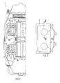
- Fig. 1 eine Draufsicht auf eine Scheibenbremse mit Betätigungskolben und Einsätzen sowie einer mit diesen verbundenen plattenförmigen Zwischenlage,
- Fig. 2 eine Draufsicht auf eine plattenförmige Zwischenlage mit Einsätzen,
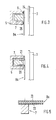
- Fig. 3 eine weitere Ausführung einer Bremsvorrichtung mit einer stirnseitig gezahnten Fläche des Betätigungskolbens und einem Einsatz mit Zwischenlage,
- Fig. 4 eine weitere Ausführung mit einer auf dem Einsatz formschlüssig gehaltenen plattenförmigen Zwischenlage und
- Fig. 5 einen Schnitt durch die plattenförmige Zwischenlage nach der Linie V-V der Fig. 2.
- 1 is a plan view of a disc brake with actuating pistons and inserts and a plate-shaped intermediate layer connected to them,
- 2 is a plan view of a plate-shaped intermediate layer with inserts,
- 3 shows a further embodiment of a braking device with an end face toothed surface of the actuating piston and an insert with an intermediate layer,
- Fig. 4 shows another embodiment with a plate-shaped intermediate layer held on the insert in a form-fitting manner
- 5 shows a section through the plate-shaped intermediate layer along the line VV of FIG. 2nd
Fig. 1 zeigt eine Bremsvorrichtung 1 eines Fahrzeugrades, die einen Bremssattel 2 mit geführten Bremsbacken 3 umfaßt, zwischen denen eine Bremsscheibe 4 angeordnet ist. Über hydraulisch beaufschlagbare Betätigungskolben 5 werden diese beim Bremsvorgang gegen die Bremsscheibe 4 gepreßt. In jedem Betätigungskolben 5 ist eine der Bremsbacke 3 zugerichtete konzentrische Bohrung 6 vorgesehen, in der ein zylinderförmiges Einsatzteil 7 angeordnet ist. Es umfaßt an seinem der Bremsbacke 3 zugerichtetem vorderen Ende ein die Kolbenstirnfläche 9 überdeckendes Element in Form einer plattenförmigen Zwischenlage 8a, die der rückseitigen Bremsbackenfläche 24 unmittelbar gegenübersteht. Das Einsatzteils 7 ist mit einem radialen Spiel 11 zur Innenumfangsfläche 13 und mit einem axialen Spiel 12 zur Bodenfläche 14 in der Bohrung 6 gehalten, wobei es sich über die plattenförmige Zwischenlage 8a zur Kolbenstirnfläche 9 hin abstützt.Fig. 1 shows a brake device 1 of a vehicle wheel, which comprises a
Die Zwischenlage 8a ist mit den beiden Einsatzteilen 7 verbunden, z.B. durch eine Nietung, Schraubung, Klebung oder dergleichen Verbindungsverfahren bzw. durch eine formschlüssige Verbindung.The intermediate layer 8a is connected to the two
Insbesondere ist die Zwischenlage 8a aus einem metallischen Werkstoff bestehend und beidseitig mit dünnen reibungserhöhenden Schichten wie z.B. Gummischichten 22 und 23 oder Lackschichten belegt.In particular, the intermediate layer 8a is made of a metallic material and has thin friction-increasing layers on both sides,
Die Größe der Zwischenlage 8a entspricht etwa der rückseitigen Fläche 24 der Bremsbacke 3, so daß eine gezielte Bedämpfung von Umfangs- Reibschwingungen der Bremsbacke 3 erzielt wird.The size of the intermediate layer 8a corresponds approximately to the
Die Verbindung der plattenförmigen Zwischenlage 8a kann auch über einen Formschluß zwischen dem Einsatzteil und der Zwischenlage 8a erfolgen. Hierzu weist die Zwischenlage 8a eine hülsenförmige Ausdrückung 20 auf, die einen vorderen abgesetzten zylindrischen Bereich 21 des Einsatzteiles 7 klemmend übergreift, wie Fig. 4 näher zeigt.The connection of the plate-shaped intermediate layer 8a can also take place via a positive connection between the insert part and the intermediate layer 8a. For this purpose, the intermediate layer 8a has a sleeve-
Nach einer weiteren Ausführung kann die Stirnfläche 9 des Betätigungskolbens 5 zur Reibungserhöhung auch mit einer Verzahnung 25 versehen sein, was in Fig. 3 näher gezeigt wird.According to a further embodiment, the
Nach einer weiteren nicht gezeigten Ausführungsform kann das Einsatzteil 7 mit einem Material erhöhter Reibung entsprechend der plattenförmigen Zwischenlage 8 ummantelt sein.According to a further embodiment, not shown, the
Claims (7)
Applications Claiming Priority (2)
| Application Number | Priority Date | Filing Date | Title |
|---|---|---|---|
| DE3743290 | 1987-12-19 | ||
| DE3743290 | 1987-12-19 |
Publications (2)
| Publication Number | Publication Date |
|---|---|
| EP0321652A1 true EP0321652A1 (en) | 1989-06-28 |
| EP0321652B1 EP0321652B1 (en) | 1991-11-06 |
Family
ID=6343109
Family Applications (1)
| Application Number | Title | Priority Date | Filing Date |
|---|---|---|---|
| EP88113650A Expired - Lifetime EP0321652B1 (en) | 1987-12-19 | 1988-08-23 | Brake device |
Country Status (4)
| Country | Link |
|---|---|
| US (1) | US4886147A (en) |
| EP (1) | EP0321652B1 (en) |
| JP (1) | JPH023715A (en) |
| DE (2) | DE8717512U1 (en) |
Cited By (2)
| Publication number | Priority date | Publication date | Assignee | Title |
|---|---|---|---|---|
| DE9002441U1 (en) * | 1990-03-02 | 1990-05-03 | Dr.Ing.H.C. F. Porsche Ag, 7000 Stuttgart | Mounting device for a mass absorber |
| ITMI20091107A1 (en) * | 2009-06-23 | 2010-12-24 | Freni Brembo Spa | DEVICE FOR DAMPING VIBRATIONS IN A DISC BRAKE PAD |
Families Citing this family (6)
| Publication number | Priority date | Publication date | Assignee | Title |
|---|---|---|---|---|
| DE3927015A1 (en) * | 1989-08-16 | 1991-02-21 | Teves Gmbh Alfred | Part-lined disc brake with sound proofed brake shoes - has brake disc, brake block and springy pieces, support and saddle |
| JPH05187464A (en) * | 1992-01-13 | 1993-07-27 | Sumitomo Electric Ind Ltd | Disc brake |
| DE60040416D1 (en) * | 2000-08-07 | 2008-11-13 | Freni Brembo Spa | BRAKE PAD FOR DISC BRAKE |
| DE10106177B4 (en) * | 2001-02-10 | 2013-02-21 | Dr. Ing. H.C. F. Porsche Aktiengesellschaft | Disc brake for vehicles, in particular motor vehicles |
| JP4714642B2 (en) * | 2005-08-31 | 2011-06-29 | 曙ブレーキ工業株式会社 | Disc brake pad |
| US20080060474A1 (en) * | 2006-09-07 | 2008-03-13 | Katsumoto Mizukawa | Gearless Differential in an Integrated Hydrostatic Transmission |
Citations (2)
| Publication number | Priority date | Publication date | Assignee | Title |
|---|---|---|---|---|
| DE2854247A1 (en) * | 1978-12-15 | 1980-06-26 | Knorr Bremse Gmbh | Disc brake heat insulation system - has insulating body with radial protrusion between piston and shoe |
| GB1589118A (en) * | 1977-08-05 | 1981-05-07 | Girling Ltd | Disc brakes |
Family Cites Families (13)
| Publication number | Priority date | Publication date | Assignee | Title |
|---|---|---|---|---|
| US3684061A (en) * | 1969-05-08 | 1972-08-15 | Toyota Motor Sales Co Ltd | Disc brake |
| JPS548820B1 (en) * | 1969-09-29 | 1979-04-19 | ||
| US3885651A (en) * | 1973-04-30 | 1975-05-27 | Ferodo Sa | Brake assembly |
| US3918555A (en) * | 1974-01-22 | 1975-11-11 | Girling Ltd | Apparatus for locating a friction pad assembly to a support member |
| DE2427040B2 (en) * | 1974-06-05 | 1979-01-11 | Abex Pagid Reibbelag Gmbh, 4300 Essen | Brake body for disc brakes |
| DE2508720A1 (en) * | 1975-02-28 | 1976-09-09 | Prodak Kg I G Guenther Hoffman | Surface treatment for disc brakes - comprises coating carrier plates with resin to prevent noise |
| US4098951A (en) * | 1976-09-20 | 1978-07-04 | Interpolymer Corporation | Process for eliminating squeal in disc brakes |
| DE2722194A1 (en) * | 1977-05-17 | 1978-11-30 | Textar Gmbh | Spacer between brake caliper and piston - is heat absorbent, transmits pressure, and prevents metallic union |
| US4373615A (en) * | 1981-01-26 | 1983-02-15 | General Motors Corporation | Laminated disc brake pad assembly |
| DE3339809A1 (en) * | 1982-11-03 | 1984-05-03 | Ferodo Ltd., Manchester | Shim design for disc brake lining |
| DE3411233A1 (en) * | 1984-03-27 | 1985-10-10 | Alfred Teves Gmbh, 6000 Frankfurt | Piston for a disc brake |
| JPS6181021U (en) * | 1984-10-31 | 1986-05-29 | ||
| DE8700102U1 (en) * | 1986-01-10 | 1987-05-14 | Textar Gmbh, 5090 Leverkusen | Partially lined disc brake with damping element |
-
1987
- 1987-12-19 DE DE8717512U patent/DE8717512U1/en not_active Expired
-
1988
- 1988-08-23 DE DE8888113650T patent/DE3866090D1/en not_active Expired - Lifetime
- 1988-08-23 EP EP88113650A patent/EP0321652B1/en not_active Expired - Lifetime
- 1988-12-16 JP JP63316608A patent/JPH023715A/en active Pending
- 1988-12-19 US US07/286,165 patent/US4886147A/en not_active Expired - Fee Related
Patent Citations (2)
| Publication number | Priority date | Publication date | Assignee | Title |
|---|---|---|---|---|
| GB1589118A (en) * | 1977-08-05 | 1981-05-07 | Girling Ltd | Disc brakes |
| DE2854247A1 (en) * | 1978-12-15 | 1980-06-26 | Knorr Bremse Gmbh | Disc brake heat insulation system - has insulating body with radial protrusion between piston and shoe |
Cited By (5)
| Publication number | Priority date | Publication date | Assignee | Title |
|---|---|---|---|---|
| DE9002441U1 (en) * | 1990-03-02 | 1990-05-03 | Dr.Ing.H.C. F. Porsche Ag, 7000 Stuttgart | Mounting device for a mass absorber |
| ITMI20091107A1 (en) * | 2009-06-23 | 2010-12-24 | Freni Brembo Spa | DEVICE FOR DAMPING VIBRATIONS IN A DISC BRAKE PAD |
| WO2010150164A1 (en) | 2009-06-23 | 2010-12-29 | Freni Brembo S.P.A. | Device for damping the vibrations in a pad of a disc brake |
| JP2012531565A (en) * | 2009-06-23 | 2012-12-10 | フェルニ ブレンボ エッセ.ピー.アー. | A device that damps vibration in the disc brake pad |
| US8833529B2 (en) | 2009-06-23 | 2014-09-16 | Freni Brembo S.P.A. | Device for damping the vibrations in a pad of a disc brake |
Also Published As
| Publication number | Publication date |
|---|---|
| US4886147A (en) | 1989-12-12 |
| DE8717512U1 (en) | 1989-01-05 |
| JPH023715A (en) | 1990-01-09 |
| DE3866090D1 (en) | 1991-12-12 |
| EP0321652B1 (en) | 1991-11-06 |
Similar Documents
| Publication | Publication Date | Title |
|---|---|---|
| DE2502459B2 (en) | Damping element with at least one flexible damping layer for partially lined disc brakes | |
| DE3333670C2 (en) | Floating caliper brakes for automobiles | |
| DE2713377A1 (en) | DISC BRAKE FOR VEHICLES | |
| DE19602037B4 (en) | Brake block for a partial lining disc brake | |
| EP0321652B1 (en) | Brake device | |
| DE3744341A1 (en) | DISC BRAKE ARRANGEMENT | |
| DE4307954C2 (en) | Disc brake and brake pad clamp | |
| DE60211742T2 (en) | DISC BRAKE CALIPER FOR VEHICLES | |
| DE3402866A1 (en) | Device for suppressing the squealing of disc brakes | |
| DE1289692B (en) | Pressure medium-operated partial-lined disc brake, especially for motor vehicles | |
| EP1407160B1 (en) | Brake shoe, especially for a disc brake | |
| EP0322530B1 (en) | Brake device | |
| DE4418955B4 (en) | Fixed caliper partial brake disc brake for motor vehicles | |
| DE2901349A1 (en) | CRUSH-PROOF BRAKE DISC FOR VEHICLE BRAKES | |
| DE3247593A1 (en) | DISC BRAKE | |
| DE19707715C2 (en) | Disc brake on a motor vehicle | |
| DE4203173B4 (en) | Internal shoe drum brake for motor vehicles | |
| EP0872660B1 (en) | Device for damping the vibrations of a disc brake pad | |
| DE10006392B4 (en) | Brake pad with back cushioning agent | |
| DE19602888C1 (en) | Brake shoe, in particular for commercial vehicle disc brakes | |
| DE60010621T2 (en) | Brake unit for a rail vehicle and bogie of a rail vehicle with this device | |
| DE6805501U (en) | DISC BRAKE, IN PARTICULAR PARTICULAR DISC BRAKE | |
| DE102015114112A1 (en) | Braking device of a motor vehicle | |
| DE1804115A1 (en) | Brake pad back plate for disc brakes | |
| DE19739766C2 (en) | Block braked wheelset |
Legal Events
| Date | Code | Title | Description |
|---|---|---|---|
| PUAI | Public reference made under article 153(3) epc to a published international application that has entered the european phase |
Free format text: ORIGINAL CODE: 0009012 |
|
| AK | Designated contracting states |
Kind code of ref document: A1 Designated state(s): DE FR GB IT SE |
|
| 17P | Request for examination filed |
Effective date: 19891027 |
|
| 17Q | First examination report despatched |
Effective date: 19901217 |
|
| GRAA | (expected) grant |
Free format text: ORIGINAL CODE: 0009210 |
|
| AK | Designated contracting states |
Kind code of ref document: B1 Designated state(s): DE FR GB IT SE |
|
| REF | Corresponds to: |
Ref document number: 3866090 Country of ref document: DE Date of ref document: 19911212 |
|
| ITF | It: translation for a ep patent filed | ||
| GBT | Gb: translation of ep patent filed (gb section 77(6)(a)/1977) | ||
| ET | Fr: translation filed | ||
| PGFP | Annual fee paid to national office [announced via postgrant information from national office to epo] |
Ref country code: SE Payment date: 19920724 Year of fee payment: 5 |
|
| PGFP | Annual fee paid to national office [announced via postgrant information from national office to epo] |
Ref country code: FR Payment date: 19920729 Year of fee payment: 5 |
|
| PGFP | Annual fee paid to national office [announced via postgrant information from national office to epo] |
Ref country code: DE Payment date: 19920805 Year of fee payment: 5 |
|
| PGFP | Annual fee paid to national office [announced via postgrant information from national office to epo] |
Ref country code: GB Payment date: 19920812 Year of fee payment: 5 |
|
| PLBE | No opposition filed within time limit |
Free format text: ORIGINAL CODE: 0009261 |
|
| STAA | Information on the status of an ep patent application or granted ep patent |
Free format text: STATUS: NO OPPOSITION FILED WITHIN TIME LIMIT |
|
| 26N | No opposition filed | ||
| PG25 | Lapsed in a contracting state [announced via postgrant information from national office to epo] |
Ref country code: GB Effective date: 19930823 |
|
| PG25 | Lapsed in a contracting state [announced via postgrant information from national office to epo] |
Ref country code: SE Effective date: 19930824 |
|
| GBPC | Gb: european patent ceased through non-payment of renewal fee |
Effective date: 19930823 |
|
| PG25 | Lapsed in a contracting state [announced via postgrant information from national office to epo] |
Ref country code: FR Effective date: 19940429 |
|
| PG25 | Lapsed in a contracting state [announced via postgrant information from national office to epo] |
Ref country code: DE Effective date: 19940503 |
|
| REG | Reference to a national code |
Ref country code: FR Ref legal event code: ST |
|
| EUG | Se: european patent has lapsed |
Ref document number: 88113650.1 Effective date: 19940310 |
|
| PG25 | Lapsed in a contracting state [announced via postgrant information from national office to epo] |
Ref country code: IT Free format text: LAPSE BECAUSE OF NON-PAYMENT OF DUE FEES;WARNING: LAPSES OF ITALIAN PATENTS WITH EFFECTIVE DATE BEFORE 2007 MAY HAVE OCCURRED AT ANY TIME BEFORE 2007. THE CORRECT EFFECTIVE DATE MAY BE DIFFERENT FROM THE ONE RECORDED. Effective date: 20050823 |