EP0321670B1 - Dispositif de commande d'une soupape de détente de l'appareil frigorifique d'une installation de climatisation d'un véhicule automobile - Google Patents
Dispositif de commande d'une soupape de détente de l'appareil frigorifique d'une installation de climatisation d'un véhicule automobile Download PDFInfo
- Publication number
- EP0321670B1 EP0321670B1 EP88117426A EP88117426A EP0321670B1 EP 0321670 B1 EP0321670 B1 EP 0321670B1 EP 88117426 A EP88117426 A EP 88117426A EP 88117426 A EP88117426 A EP 88117426A EP 0321670 B1 EP0321670 B1 EP 0321670B1
- Authority
- EP
- European Patent Office
- Prior art keywords
- temperature
- evaporator
- expansion valve
- compressor
- pressure drop
- Prior art date
- Legal status (The legal status is an assumption and is not a legal conclusion. Google has not performed a legal analysis and makes no representation as to the accuracy of the status listed.)
- Expired - Lifetime
Links
Images
Classifications
-
- F—MECHANICAL ENGINEERING; LIGHTING; HEATING; WEAPONS; BLASTING
- F25—REFRIGERATION OR COOLING; COMBINED HEATING AND REFRIGERATION SYSTEMS; HEAT PUMP SYSTEMS; MANUFACTURE OR STORAGE OF ICE; LIQUEFACTION SOLIDIFICATION OF GASES
- F25B—REFRIGERATION MACHINES, PLANTS OR SYSTEMS; COMBINED HEATING AND REFRIGERATION SYSTEMS; HEAT PUMP SYSTEMS
- F25B41/00—Fluid-circulation arrangements
- F25B41/30—Expansion means; Dispositions thereof
- F25B41/31—Expansion valves
- F25B41/34—Expansion valves with the valve member being actuated by electric means, e.g. by piezoelectric actuators
- F25B41/345—Expansion valves with the valve member being actuated by electric means, e.g. by piezoelectric actuators by solenoids
- F25B41/347—Expansion valves with the valve member being actuated by electric means, e.g. by piezoelectric actuators by solenoids with the valve member being opened and closed cyclically, e.g. with pulse width modulation
-
- F—MECHANICAL ENGINEERING; LIGHTING; HEATING; WEAPONS; BLASTING
- F25—REFRIGERATION OR COOLING; COMBINED HEATING AND REFRIGERATION SYSTEMS; HEAT PUMP SYSTEMS; MANUFACTURE OR STORAGE OF ICE; LIQUEFACTION SOLIDIFICATION OF GASES
- F25B—REFRIGERATION MACHINES, PLANTS OR SYSTEMS; COMBINED HEATING AND REFRIGERATION SYSTEMS; HEAT PUMP SYSTEMS
- F25B2600/00—Control issues
- F25B2600/21—Refrigerant outlet evaporator temperature
-
- F—MECHANICAL ENGINEERING; LIGHTING; HEATING; WEAPONS; BLASTING
- F25—REFRIGERATION OR COOLING; COMBINED HEATING AND REFRIGERATION SYSTEMS; HEAT PUMP SYSTEMS; MANUFACTURE OR STORAGE OF ICE; LIQUEFACTION SOLIDIFICATION OF GASES
- F25B—REFRIGERATION MACHINES, PLANTS OR SYSTEMS; COMBINED HEATING AND REFRIGERATION SYSTEMS; HEAT PUMP SYSTEMS
- F25B2700/00—Sensing or detecting of parameters; Sensors therefor
- F25B2700/21—Temperatures
- F25B2700/2117—Temperatures of an evaporator
- F25B2700/21174—Temperatures of an evaporator of the refrigerant at the inlet of the evaporator
-
- F—MECHANICAL ENGINEERING; LIGHTING; HEATING; WEAPONS; BLASTING
- F25—REFRIGERATION OR COOLING; COMBINED HEATING AND REFRIGERATION SYSTEMS; HEAT PUMP SYSTEMS; MANUFACTURE OR STORAGE OF ICE; LIQUEFACTION SOLIDIFICATION OF GASES
- F25B—REFRIGERATION MACHINES, PLANTS OR SYSTEMS; COMBINED HEATING AND REFRIGERATION SYSTEMS; HEAT PUMP SYSTEMS
- F25B2700/00—Sensing or detecting of parameters; Sensors therefor
- F25B2700/21—Temperatures
- F25B2700/2117—Temperatures of an evaporator
- F25B2700/21175—Temperatures of an evaporator of the refrigerant at the outlet of the evaporator
-
- Y—GENERAL TAGGING OF NEW TECHNOLOGICAL DEVELOPMENTS; GENERAL TAGGING OF CROSS-SECTIONAL TECHNOLOGIES SPANNING OVER SEVERAL SECTIONS OF THE IPC; TECHNICAL SUBJECTS COVERED BY FORMER USPC CROSS-REFERENCE ART COLLECTIONS [XRACs] AND DIGESTS
- Y02—TECHNOLOGIES OR APPLICATIONS FOR MITIGATION OR ADAPTATION AGAINST CLIMATE CHANGE
- Y02B—CLIMATE CHANGE MITIGATION TECHNOLOGIES RELATED TO BUILDINGS, e.g. HOUSING, HOUSE APPLIANCES OR RELATED END-USER APPLICATIONS
- Y02B30/00—Energy efficient heating, ventilation or air conditioning [HVAC]
- Y02B30/70—Efficient control or regulation technologies, e.g. for control of refrigerant flow, motor or heating
Definitions
- the invention relates to a refrigeration system for a motor vehicle, with a compressor, a condenser, a controllable expansion valve and an evaporator, which are connected to form a closed circuit via lines, a first temperature sensor, the temperature in the line between the evaporator and the compressor, a second temperature sensor to measure the temperature in the line between the expansion valve and the evaporator and a third temperature sensor to measure the temperature before entering the evaporator and from this a control variable for the expansion valve is derived.
- a refrigeration system is known from GB-A-639 683.
- the three sensors belong to one and the same control device of this refrigeration system, which acts on the expansion valve depending on the measurement results.
- the second and third sensors are assigned to the connecting line between the expansion valve and the evaporator, which is why they determine the exact same temperature value.
- the first sensor is connected between the compressor and the evaporator, which is why it detects a different temperature value.
- All three temperature sensors are connected to a thermostat via capillary lines and all three thermostats belong to the control valve. A setpoint is set on the latter. If this is exceeded, the thermostat of the second sensor carries out a switching operation. As soon as the temperature difference at the first and third sensors has reached a certain value, another switching process takes place, with which the expansion valve is closed and the further generation of cold is thereby prevented.
- the invention is therefore based on the object of determining the overheating of the refrigerant before entering the compressor as an output variable for controlling the expansion valve of a refrigeration device in a motor vehicle on the basis of temperature measurements and thereby ensuring that the compressor Refrigerant is only supplied in the gaseous state.
- this object is achieved in a refrigeration system of the generic type in that it is designed in accordance with the characterizing part of claim 1.
- the computing unit can be transmitted a total of three different temperature values, which are converted by it into a control signal for the expansion valve, which actuates the expansion valve in the desired manner and thereby ensures that the overheating of the refrigerant passing into the compressor has a predetermined value Value reached and the temperatures T1 and T2 each correspond to a value at which the refrigerant is in the wet steam range in all operating states.
- the two temperature sensors in front of and behind the device causing the pressure drop record two different states of the refrigerant via the temperature measurements.
- the difference between these signals is one of the control criteria.
- these signals are processed into control commands for the expansion valve in order to take account of the requirements.
- the expansion valve then in turn ensures that the desired pressure drop can take place, for example, at the venturi distributor, so that the refrigerant on the second and third sensors is in the wet steam range in all operating states. This ensures that saturation temperatures are always measured.
- the wet steam area is the bell-shaped area within which the refrigerant is present as a two-phase system, that is to say both as a vapor and as a liquid.
- the device causing the pressure drop is, for example, a venturi distributor with a plurality of drain lines, a vortex cell or a measuring orifice. All of these devices cause a pressure drop and thereby enable the measurement of two different temperatures in front of and behind the device or the detection of two different states of the refrigerant.
- the manipulated variable is then determined in such a way that the overheating always has the specific predetermined value.
- a manipulated variable for the expansion valve can then be derived in a manner known per se by a computing unit. For example, if the overheating is too great, the evaporator is underfilled with liquid. The degree of opening of the expansion valve, which is controlled by actuators known per se, is increased in this case until the desired overheating, calculated from the measured temperatures, occurs again, etc.
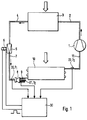
- the cooling device consists of compressor 1, line 2, condenser 3, line 4, expansion valve 5, which is clocked by a solenoid 6, line 7, venturi distributor 8, several lines 9, evaporator 10 and line 11.
- the air flowing through the condenser 3 cools it.
- the air flowing through the evaporator is cooled by the evaporator.
- the condenser is usually exposed to the wind, while the evaporator is traversed by the air to be cooled in the interior of a motor vehicle.
- the temperature sensor 20 is located in line 7 in front of the venturi distributor 8.
- the temperature sensor 21 is located on one of the lines 9 behind the venturi distributor 8.
- the lines 9 are all passed through the evaporator 10 after the refrigerant flow in the venturi distributor 8 has been divided into equal substreams is.
- the temperature sensor 22 is located behind the evaporator 10, that is to say in front of the compressor 1.
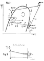
- part of the refrigerant changes its state of matter from the liquid to the gaseous phase, as a result of which the refrigerant cools to the lower temperature T2, the rest of the liquid phase evaporates in the evaporator 10 by removing heat from the surroundings, so that a temperature of 5 ° C can be given at the outlet of the evaporator at a pressure of about 3 bar.
- the solid and bell-like curve X drawn somewhat thicker than the other lines, describes the wet steam area, i.e. the area in which, under the condition conditions of the coolant defined thereby, it is present both in the steam phase and in the liquid phase.
- Overheating refers to the fact that the temperature is higher than the temperature at which the coolant changes from the liquid phase to the gaseous phase. The greater the overheating, the safer the refrigerant is in the gaseous phase.
- a temperature must be given at the input of the compressor 1 which can be expected with certainty that the entire refrigerant is in the gaseous phase, that is to say has completely evaporated. Is this e.g. not the case, i.e. if the temperature is lower, this means that too much refrigerant has entered the evaporator.
- the expansion valve must e.g. controlled by clocking so that less refrigerant passes through. The temperature behind the evaporator or before the refrigerant enters the compressor then becomes correspondingly higher.
- the arrangement of the temperature sensors 20, 21, 22 is shown in FIG. 2 also designated by the reference numerals 20, 21, 22. Through these points in the cycle, the dashed isotherms T1, T2 and T3 go. It can be seen that, as mentioned, the temperature sensors 20, 21 are inside the curve X and the temperature sensors 22 are outside the curve X.
- the lower, dashed line in Figure 3 is undesirable because it provides a temperature T'3 too low.
- the upper of the two courses delivers a temperature T3, which is higher by the desired amount ⁇ tü.
- ⁇ tü T3-T2 + k (T1-T2).
- k is a constant that depends on the design of the evaporator.
- the size k is determined in the manner already outlined and ultimately represents the ratio of the refrigerant-side pressure drop in the evaporator tube to the comparative pressure drop of the orifice plate.
- the measuring point for T 1 and T 2 should be arranged such that the constant k is approximately 1 at least but within the limits 0.5 ⁇ k ⁇ 1.5.
- a corresponding control signal is, for example, a sequence of rectangular pulses of a certain length. The length and the distance of the rectangular pulses determine the temporal relationship between opening and closing of the expansion valve 5, so that the amount of coolant passing through the expansion valve is controlled in this way.
Landscapes
- Engineering & Computer Science (AREA)
- Physics & Mathematics (AREA)
- Mechanical Engineering (AREA)
- Thermal Sciences (AREA)
- General Engineering & Computer Science (AREA)
- Air-Conditioning For Vehicles (AREA)
Claims (3)
- Installation de refroidissement pour un véhicule automobile, comprenant un compresseur (1), un condenseur (3), une soupape de détente asservissable (5) et un évaporateur (10), qui sont mutuellement reliés par des conduites (2, 4, 7, 11) pour former un circuit fermé, un premier capteur de température (22) mesurant la température (T₃) dans la conduite (11) entre l'évaporateur (10) et le compresseur (1), un deuxième capteur de température (20) mesurant la température (T₁) dans la conduite (7) entre la soupape de détente (5) et l'évaporateur (10) et un troisième capteur de température (21) mesurant la température (T₂) avant l'entrée dans l'évaporateur (10), et une grandeur de commande pour la soupape de détente (5) étant déduite de ces mesures, caractérisée en ce qu'un dispositif (8) produisant une chute de pression se trouve dans la conduite (7) entre la soupape de détente (5) et l'évaporateur (10), et le deuxième capteur de température (20) pour la température (T₁) est disposé, dans la direction d'écoulement, avant et le troisième capteur de température (21) pour la température (T₂) après le dispositif, chaque fois dans une région dans laquelle le réfrigérant se trouve à l'état de vapeur humide dans tous les états de service, et en ce que, dans une unité de calcul (30) et à partir des trois valeurs de température (T₁, T₂, T₃) et d'une constante qui prend en compte la chute de pression du réfrigérant dans le tube d'évaporateur par rapport à la chute de pression dans le dispositif (8), la grandeur de commande est formée de telle sorte que la surchauffe (Δtü) du réfrigérant passant dans le compresseur (1) correspond à une valeur prédéterminée.
- Installation de refroidissement selon la revendication 1, caractérisée en ce que le dispositif produisant la chute de pression est un distributeur venturi (8) à plusieurs conduites de sortie (9), une cellule de tourbillonnement ou un orifice de mesure.
- Installation de refroidissement selon la revendication 1 ou 2, caractérisée en ce que la surchauffe (Δtü) est, dans l'unité de calcul (30) et à partir des températures (T₁, T₂, T₃) mesurées au moyen des trois capteurs de température (20, 21, 22), calculée selon la formule

où k est la constante spécifique de l'évaporateur.
Applications Claiming Priority (2)
| Application Number | Priority Date | Filing Date | Title |
|---|---|---|---|
| DE19873743285 DE3743285A1 (de) | 1987-12-19 | 1987-12-19 | Vorrichtung zur ansteuerung des expansionsventils der kaelteeinrichtung bei einer kraftfahrzeug-klimaanlage |
| DE3743285 | 1987-12-19 |
Publications (3)
| Publication Number | Publication Date |
|---|---|
| EP0321670A2 EP0321670A2 (fr) | 1989-06-28 |
| EP0321670A3 EP0321670A3 (en) | 1990-05-23 |
| EP0321670B1 true EP0321670B1 (fr) | 1992-07-22 |
Family
ID=6343106
Family Applications (1)
| Application Number | Title | Priority Date | Filing Date |
|---|---|---|---|
| EP88117426A Expired - Lifetime EP0321670B1 (fr) | 1987-12-19 | 1988-10-19 | Dispositif de commande d'une soupape de détente de l'appareil frigorifique d'une installation de climatisation d'un véhicule automobile |
Country Status (2)
| Country | Link |
|---|---|
| EP (1) | EP0321670B1 (fr) |
| DE (2) | DE3743285A1 (fr) |
Families Citing this family (5)
| Publication number | Priority date | Publication date | Assignee | Title |
|---|---|---|---|---|
| US5186021A (en) * | 1991-05-20 | 1993-02-16 | Carrier Corporation | Bypass expansion device having defrost optimization mode |
| DE4436925C2 (de) * | 1994-10-15 | 1998-05-14 | Danfoss As | Regeleinrichtung für die Überhitzungstemperatur wenigstens eines Verdampfers einer Kälteanlage |
| CN101600916B (zh) * | 2006-12-29 | 2014-05-07 | 开利公司 | 控制空调系统的方法以及控制系统装置 |
| KR20080069824A (ko) * | 2007-01-24 | 2008-07-29 | 삼성전자주식회사 | 공기조화기의 과열도 제어시스템 및 그 방법 |
| EP4079549B1 (fr) | 2021-04-21 | 2024-04-24 | Ningbo Geely Automobile Research & Development Co., Ltd. | Procédé de commande d'un système de réfrigération d'un véhicule |
Family Cites Families (13)
| Publication number | Priority date | Publication date | Assignee | Title |
|---|---|---|---|---|
| GB639683A (en) * | 1947-11-07 | 1950-07-05 | J & E Hall Ltd | Improvements in apparatus for the control of expansion valves of refrigerators |
| US3478534A (en) * | 1967-08-11 | 1969-11-18 | Controls Co Of America | Thermistor controlled refrigeration expansion valve |
| US3538717A (en) * | 1968-12-04 | 1970-11-10 | Controls Co Of America | Refrigeration system control arrangement including heat motor operated expansion valve |
| US3659783A (en) * | 1969-10-24 | 1972-05-02 | Eaton Yale & Towne | Temperature regulated flow control element for automotive air-conditioners |
| DE2530021C3 (de) * | 1975-07-04 | 1980-07-31 | Fiat S.P.A., Turin (Italien) | Steuerventil für eine Kühlanlage eines Kraftfahrzeuges |
| CA1087412A (fr) * | 1976-03-04 | 1980-10-14 | Charles D. Orth | Detendeur thermostatique |
| DE3220420A1 (de) * | 1982-05-29 | 1983-12-15 | Vereinigte Elektrizitätswerke Westfalen AG, 4600 Dortmund | Verfahren zur regelung eines elektrisch ansteuerbaren expansionsventils |
| EP0133512B1 (fr) * | 1983-08-06 | 1987-10-14 | Joh. Vaillant GmbH u. Co. | Réglage d'écoulement pour un réfrigérant d'une pompe à chaleur |
| CA1247385A (fr) * | 1984-07-02 | 1988-12-28 | Kosaku Sayo | Dispositif de debitmetrie du frigorigene au cours d'un cycle de refrigeration |
| JPH0686960B2 (ja) * | 1985-01-30 | 1994-11-02 | 株式会社日立製作所 | 冷媒流量制御装置 |
| JPS61256153A (ja) * | 1985-05-08 | 1986-11-13 | 株式会社豊田自動織機製作所 | 車両空調装置 |
| DE3601817A1 (de) * | 1986-01-22 | 1987-07-23 | Egelhof Fa Otto | Regelvorrichtung fuer den kaeltemittelzustrom zum verdampfer von kaelteanlagen oder waermepumpen sowie im kaeltemittelstrom angeordnete expansionsventile |
| US4689968A (en) * | 1986-03-21 | 1987-09-01 | Danfoss A/S | Actuator means for the control of a refrigeration system expansion valve |
-
1987
- 1987-12-19 DE DE19873743285 patent/DE3743285A1/de not_active Withdrawn
-
1988
- 1988-10-19 EP EP88117426A patent/EP0321670B1/fr not_active Expired - Lifetime
- 1988-10-19 DE DE8888117426T patent/DE3873055D1/de not_active Expired - Fee Related
Also Published As
| Publication number | Publication date |
|---|---|
| EP0321670A3 (en) | 1990-05-23 |
| DE3873055D1 (de) | 1992-08-27 |
| EP0321670A2 (fr) | 1989-06-28 |
| DE3743285A1 (de) | 1989-06-29 |
Similar Documents
| Publication | Publication Date | Title |
|---|---|---|
| DE69515912T2 (de) | Vorwärtsgekoppelte regelung eines entspannungsventils | |
| DE69402195T2 (de) | Innenraumklimaregler | |
| DE69526980T2 (de) | Klimagerät mit nichtazeotropischem Kältemittel und Steuerungsinformation-Erfassungsgerät | |
| DE4213011C2 (de) | Kühlmittelkreislauf mit Steuerung einer Spareinrichtung | |
| DE69730613T2 (de) | Modulierende flüssigkeitsregelvorrichtung | |
| DE3900692C2 (de) | Kälteanlage | |
| DE4031113C2 (fr) | ||
| DE3713869A1 (de) | Regelgeraet fuer die ueberhitzungstemperatur des verdampfers einer kaelte- oder waermepumpanlage | |
| CH636442A5 (de) | Waermeinhalt-vergleichseinrichtung. | |
| EP0559043B1 (fr) | Méthode de contrÔle des échangeurs de chaleur | |
| DE3818321A1 (de) | Klimapruefkammer | |
| DE4436925C2 (de) | Regeleinrichtung für die Überhitzungstemperatur wenigstens eines Verdampfers einer Kälteanlage | |
| DE1812037A1 (de) | Regelsystem fuer die Kuehlvorrichtungen einer Klimaanlage | |
| DE102004035879A1 (de) | Kühlsystem, insbesondere für ein Kraftfahrzeug, und Verfahren zum Kühlen einer Wärmequelle | |
| DE69319871T2 (de) | Verfahren und System zur Steuerung der Heiz- oder Kühlleistung in Heizungs- oder Klimaanlagen | |
| DE3229779C2 (fr) | ||
| CH707678A1 (de) | Verfahren und System zum Temperieren von Bauteilen. | |
| EP1920954B1 (fr) | Procédé de régulation d'une installation de climatisation de véhicule automobile dotée d'au moins deux évaporateurs | |
| EP0321670A2 (fr) | Dispositif de commande d'une soupape de détente de l'appareil frigorifique d'une installation de climatisation d'un véhicule automobile | |
| WO2019001683A1 (fr) | Procédé et dispositif de surveillance d'un échangeur de chaleur | |
| DE3344599C1 (de) | Resorptions-Wärmewandleranlage | |
| DE3340736A1 (de) | Regeleinrichtung fuer einen kuehlkreislauf | |
| WO2016055162A1 (fr) | Procédé de régultation d'un système d'échangeurs de chaleur couplés et système d'échangeurs de chaleur | |
| DE3101081C2 (de) | Leistungssteuereinrichtung für eine Absorptionskälteanlage | |
| EP2751494A2 (fr) | Procédé pour faire fonctionner un appareil échangeur de chaleur liquide-air |
Legal Events
| Date | Code | Title | Description |
|---|---|---|---|
| PUAI | Public reference made under article 153(3) epc to a published international application that has entered the european phase |
Free format text: ORIGINAL CODE: 0009012 |
|
| AK | Designated contracting states |
Kind code of ref document: A2 Designated state(s): DE ES FR GB IT SE |
|
| PUAL | Search report despatched |
Free format text: ORIGINAL CODE: 0009013 |
|
| AK | Designated contracting states |
Kind code of ref document: A3 Designated state(s): DE ES FR GB IT SE |
|
| RAP1 | Party data changed (applicant data changed or rights of an application transferred) |
Owner name: BEHR GMBH & CO. |
|
| 17P | Request for examination filed |
Effective date: 19900809 |
|
| 17Q | First examination report despatched |
Effective date: 19910221 |
|
| GRAA | (expected) grant |
Free format text: ORIGINAL CODE: 0009210 |
|
| AK | Designated contracting states |
Kind code of ref document: B1 Designated state(s): DE ES FR GB IT SE |
|
| PG25 | Lapsed in a contracting state [announced via postgrant information from national office to epo] |
Ref country code: IT Free format text: LAPSE BECAUSE OF FAILURE TO SUBMIT A TRANSLATION OF THE DESCRIPTION OR TO PAY THE FEE WITHIN THE PRE;WARNING: LAPSES OF ITALIAN PATENTS WITH EFFECTIVE DATE BEFORE 2007 MAY HAVE OCCURRED AT ANY TIME BEFORE 2007. THE CORRECT EFFECTIVE DATE MAY BE DIFFERENT FROM THE ONE RECORDED.SCRIBED TIME-LIMIT Effective date: 19920722 Ref country code: ES Free format text: THE PATENT HAS BEEN ANNULLED BY A DECISION OF A NATIONAL AUTHORITY Effective date: 19920722 Ref country code: SE Effective date: 19920722 Ref country code: GB Effective date: 19920722 |
|
| REF | Corresponds to: |
Ref document number: 3873055 Country of ref document: DE Date of ref document: 19920827 |
|
| ET | Fr: translation filed | ||
| GBV | Gb: ep patent (uk) treated as always having been void in accordance with gb section 77(7)/1977 [no translation filed] |
Effective date: 19920722 |
|
| PLBE | No opposition filed within time limit |
Free format text: ORIGINAL CODE: 0009261 |
|
| STAA | Information on the status of an ep patent application or granted ep patent |
Free format text: STATUS: NO OPPOSITION FILED WITHIN TIME LIMIT |
|
| 26N | No opposition filed | ||
| PGFP | Annual fee paid to national office [announced via postgrant information from national office to epo] |
Ref country code: FR Payment date: 19981020 Year of fee payment: 11 |
|
| PGFP | Annual fee paid to national office [announced via postgrant information from national office to epo] |
Ref country code: DE Payment date: 19981023 Year of fee payment: 11 |
|
| PG25 | Lapsed in a contracting state [announced via postgrant information from national office to epo] |
Ref country code: FR Free format text: LAPSE BECAUSE OF NON-PAYMENT OF DUE FEES Effective date: 20000630 |
|
| PG25 | Lapsed in a contracting state [announced via postgrant information from national office to epo] |
Ref country code: DE Free format text: LAPSE BECAUSE OF NON-PAYMENT OF DUE FEES Effective date: 20000801 |
|
| REG | Reference to a national code |
Ref country code: FR Ref legal event code: ST |