EP0321678A1 - Buse d'injection et dispositif de moulage d'injection - Google Patents
Buse d'injection et dispositif de moulage d'injection Download PDFInfo
- Publication number
- EP0321678A1 EP0321678A1 EP88117916A EP88117916A EP0321678A1 EP 0321678 A1 EP0321678 A1 EP 0321678A1 EP 88117916 A EP88117916 A EP 88117916A EP 88117916 A EP88117916 A EP 88117916A EP 0321678 A1 EP0321678 A1 EP 0321678A1
- Authority
- EP
- European Patent Office
- Prior art keywords
- nozzle
- section
- injection molding
- channel
- mouth
- Prior art date
- Legal status (The legal status is an assumption and is not a legal conclusion. Google has not performed a legal analysis and makes no representation as to the accuracy of the status listed.)
- Granted
Links
- 238000001746 injection moulding Methods 0.000 title claims description 49
- 238000002347 injection Methods 0.000 title abstract description 6
- 239000007924 injection Substances 0.000 title abstract description 6
- 239000000463 material Substances 0.000 claims abstract description 56
- 238000009826 distribution Methods 0.000 claims abstract description 26
- 230000004323 axial length Effects 0.000 claims abstract description 6
- 239000007921 spray Substances 0.000 claims description 19
- 238000000034 method Methods 0.000 claims description 12
- 238000005452 bending Methods 0.000 claims description 9
- 238000010438 heat treatment Methods 0.000 claims description 9
- 239000012815 thermoplastic material Substances 0.000 claims description 5
- 229910000831 Steel Inorganic materials 0.000 claims description 4
- 229910001220 stainless steel Inorganic materials 0.000 claims description 4
- 239000010935 stainless steel Substances 0.000 claims description 4
- 239000010959 steel Substances 0.000 claims description 4
- 238000004519 manufacturing process Methods 0.000 claims description 3
- 238000007664 blowing Methods 0.000 claims description 2
- 238000007142 ring opening reaction Methods 0.000 claims 1
- 238000006073 displacement reaction Methods 0.000 abstract description 3
- 239000004020 conductor Substances 0.000 description 3
- 230000000694 effects Effects 0.000 description 3
- 238000000465 moulding Methods 0.000 description 3
- 238000009413 insulation Methods 0.000 description 2
- 239000004033 plastic Substances 0.000 description 2
- 238000012545 processing Methods 0.000 description 2
- 238000004873 anchoring Methods 0.000 description 1
- 238000005266 casting Methods 0.000 description 1
- 238000001816 cooling Methods 0.000 description 1
- 230000001186 cumulative effect Effects 0.000 description 1
- 238000013461 design Methods 0.000 description 1
- 239000007788 liquid Substances 0.000 description 1
- 210000000056 organ Anatomy 0.000 description 1
- 230000002093 peripheral effect Effects 0.000 description 1
- 230000010512 thermal transition Effects 0.000 description 1
- 229920001169 thermoplastic Polymers 0.000 description 1
- 239000004416 thermosoftening plastic Substances 0.000 description 1
- 238000012549 training Methods 0.000 description 1
- 238000012546 transfer Methods 0.000 description 1
- 230000007704 transition Effects 0.000 description 1
- 238000010792 warming Methods 0.000 description 1
Images

Classifications
-
- B—PERFORMING OPERATIONS; TRANSPORTING
- B29—WORKING OF PLASTICS; WORKING OF SUBSTANCES IN A PLASTIC STATE IN GENERAL
- B29C—SHAPING OR JOINING OF PLASTICS; SHAPING OF MATERIAL IN A PLASTIC STATE, NOT OTHERWISE PROVIDED FOR; AFTER-TREATMENT OF THE SHAPED PRODUCTS, e.g. REPAIRING
- B29C45/00—Injection moulding, i.e. forcing the required volume of moulding material through a nozzle into a closed mould; Apparatus therefor
- B29C45/17—Component parts, details or accessories; Auxiliary operations
- B29C45/26—Moulds
- B29C45/27—Sprue channels ; Runner channels or runner nozzles
- B29C45/28—Closure devices therefor
- B29C45/2806—Closure devices therefor consisting of needle valve systems
Definitions
- the present invention relates to a method for loading an injection molding nozzle with a nozzle channel with a nozzle orifice in a nozzle body, a nozzle assembly that extends coaxially with the axis of the orifice and is axially displaceable to control the discharge of material from the nozzle orifice and is guided in the nozzle body away from the orifice for this movement , as well as with a feed line arrangement for sprayed material which extends through the nozzle body and is at an angle to the mouth axis.
- the invention further relates to an injection molding nozzle with a nozzle body, therein a nozzle channel with a nozzle orifice, further a coaxial to the nozzle orifice, which controls the outlet from the nozzle orifice, which is guided in the nozzle body, and with a feed line arrangement in the nozzle body which is inclined to the orifice axis. Furthermore, the present invention relates to an injection molding device with such a nozzle and a use of the method mentioned or the injection molding nozzle or the injection molding device mentioned.
- the nozzle assembly on the nozzle body is guided to perform an axial back and forth movement, the nozzle assembly is mounted on a hot conductor block, the latter of which has play with respect to the nozzle assembly, so that the nozzle body and the hot runner block can move thermally relative to one another without impairing the nozzle assembly. Because of this guidance of the nozzle assembly on the nozzle body, the feed line from the hot-runner block to the nozzle channel section is arranged at an oblique angle with respect to the nozzle axis.
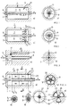
- FIG. 1 This known arrangement is shown schematically in FIG. 1.
- a nozzle opening 5 for dispensing the sprayed material, which communicates with an axially extended nozzle channel section 7.
- a nozzle block 9 is arranged coaxially, which is moved out of this opening 5 by axial displacement A into the nozzle opening or mouth 5, and as indicated by dashed lines.
- the axial extent of the nozzle channel section 7, which is inside through the nozzle assembly 9 is limited, and thus the free length of the nozzle assembly 9, is considerably longer than the diameter of the nozzle assembly 9.
- the hot, liquid spray material is radially staggered from the opening 5 in a discreet location or inlet opening 11 from a feed line 13 in injected the nozzle channel section 7.
- a cross-sectional area Q is considered in accordance with FIG. 1b, distribution of the pressure p on the circumference of the nozzle assembly 9 results from the inlet opening 11 when the sprayed material is injected under pressure, as is shown qualitatively in FIG. 1b: This results on the inlet opening side, through which Pressure-flowing material, a higher pressure on the part of the nozzle assembly 9 facing this opening 11 than on the side facing away from this opening 11. This results, as indicated schematically in FIG. 1a, in a force distribution which is not uniformly distributed around the circumference of the nozzle assembly 9 and which exerts a bending stress on the nozzle assembly 9, which, depending on the position of the nozzle assembly 9 with respect to the nozzle opening 5, is greater or weaker deflections of the stick.
- This arrangement has the disadvantage that the asymmetrical inflow conditions to the nozzle mouth cause asymmetrical friction conditions and thus heating in the conveyed goods and thus, particularly when processing PET material in this regard, lead to asymmetries in the dispensing of the goods into a mold.
- a method or an injection molding nozzle has become known from FR-A-2 333 633, wherein a nozzle assembly can be pushed back and forth coaxially with a nozzle orifice.
- the nozzle assembly runs in a Hesiz cartridge case, in which a heating coil is arranged to heat the nozzle assembly.
- An outer sleeve holds the heating coil and is led directly into the mouth area of the nozzle, where it holds the nozzle assembly.
- a feed line arrangement is provided, through which a coaxial nozzle channel arrangement around the sleeve mentioned is applied symmetrically to the axis of the nozzle or nozzle orifice.
- axially symmetrically arranged pairs of slots are provided in order to feed the spray material to the coaxial channel mentioned.
- the aim of the present invention is, based on a method of the type mentioned above, to remedy the disadvantage mentioned, which is achieved by training according to the wording of the characterizing part of claim 1.
- the axial length of the section in which the nozzle block acts as the inner boundary of the coaxially annular nozzle channel when the nozzle block is extended correspondingly extends
- the diameter of the nozzle assembly in this section is chosen to be so short that a bending stress due to an asymmetrical pressure distribution in the sprayed material can only result in a negligible deflection of the nozzle assembly, based on the narrow tolerances of the nozzle orifice and the tip of the nozzle assembly, that any pressure asymmetry in said Section cannot deflect the nozzle assembly to an impairing extent. This, even if, as by feeding the goods in, on a discrete peripheral section of this section, this feeding takes place extremely asymmetrically.
- the section is sprayed with essentially uniformly distributed pressure around the nozzle assembly.
- both measures are preferably used cumulatively, in view of the geometrically very narrow tolerances between the tip of the nozzle and the orifice, according to which the tip of the nozzle must be able to be inserted smoothly and exactly flush into the mouth of the nozzle.
- the axial length of the section mentioned is preferably chosen to be 0.5 to 2 times the diameter of the nozzle assembly in this section.
- the second is preferably cumulative and preferably in that the spray material is first conveyed axially symmetrically separately from the nozzle assembly and then conveyed axially symmetrically into the section.
- the initially axially symmetrical, but separate from the nozzle assembly, results in a pressure equalization, without this having any influence on the nozzle assembly, so that when the material to be sprayed is finally transferred into the section, there is an axially symmetrical pressure distribution.
- An injection molding device according to the invention with such an injection molding nozzle according to the invention is distinguished by the wording of claim 13.
- thermoplastic casting materials such as PET
- a heating arrangement for the spray material feed arrangement to the nozzle, in order to keep the spray material on its way to one or more of the nozzles provided in a spray-viscous manner.
- the nozzle be thermally closely coupled to the heating arrangement, such as by a steel connection, in order to ensure that the temperature distribution of organs in contact with the material is as uniform as possible along the feed path through the device to the nozzle to step. It is generally proposed below that the nozzle is thermally more closely coupled with device parts operated at a high temperature level, such as heating elements for the supply line arrangement, than with device parts operated at a lower temperature level, such as the mold base mentioned above.
- the nozzle can be inserted into a receptacle on the device.
- the nozzle is rigidly fixed after being pushed in by providing appropriately tensioned bearings and abutments.
- FIG. 2a shows an injection molding nozzle 1 according to the invention in a first embodiment variant, with a nozzle opening 5 in a nozzle head 3.
- a nozzle duct 7 runs according to A back and forth movable nozzle assembly 9, which is exposed in the nozzle channel 7.
- the nozzle channel 7, the outlet of which is controlled by the nozzle opening or mouth 5 with the nozzle assembly 9, is now supplied with sprayed material by a feed arrangement 15 which extends through the nozzle body 2 at an angle to the nozzle axis A, which ensures that, as shown in FIG. 2 b and again viewed on the cross-sectional area Q, a uniform pressure distribution is created on the circumference of the nozzle assembly 9.
- said feed arrangement 15 comprises a plurality of feed openings uniformly distributed on the circumference of the nozzle channel 7 in the nozzle body 2, all of which act in the nozzle channel 7 with the same good output pressure.
- FIG. 3 shows a further embodiment variant of an injection molding nozzle according to the invention.
- An extension of the service life of the nozzle stick tip or nozzle opening 5 is achieved in that the free length mit with which the nozzle stick 9 projects through the nozzle channel 7 is small, preferably in the order of magnitude of the diameter dimension, preferably 0.5-2 times that Diameter dimension of the nozzle assembly 9 in the channel 7 is selected.
- the material to be injected is fed into the channel 7 via a feed arrangement 15, which leads parallel to the nozzle assembly 9 to directly into the area of the nozzle opening 5. If the nozzle assembly has not been completely retrieved, the nozzle channel 7 is practically designed as an annular chamber.
- Fig. 4 which is described below, techniques according to Fig. 3 and according to Fig. 2 are preferably combined, i.e. Both the free length l of the nozzle assembly is selected to be as short as possible and the supply of material is preferably carried out with symmetrically distributed pressure on the nozzle assembly 9.
- FIG. 4a shows a further preferred embodiment variant of a nozzle 1 according to the invention. It is again assumed that existing injection molding devices are provided with feeds to the nozzle channels, which are guided "asymmetrically" at a discrete circumferential part with respect to the nozzle assembly at an oblique angle to the nozzle axis. Apart from that, the embodiment variant shown here brings further advantages, which will still be mentioned.
- a guide sleeve 19 is provided here, which is anchored at its end facing away from the nozzle opening 5 in the nozzle body 2 and in whose bore 21, at least facing the nozzle opening 5, the nozzle assembly 9 is guided in a sealingly movable manner.
- the guide sleeve 19 in a manner to be described below, one or more connecting channels, a connecting channel arrangement, are arranged axially parallel to the axis of the nozzle assembly 9, symmetrically or coaxially 23, defined along which sprayed material flows axially parallel to the nozzle shaft axis towards the nozzle opening 5, without first coming into contact with the nozzle block 9.
- This distribution channel arrangement 23 can now be loaded asymmetrically with respect to the nozzle assembly 9 with a single supply line 25 at an end of the distribution channel arrangement 23 set back with respect to the end of the sleeve 19: while the spray material flows axially parallel to the front, pressure equalization occurs, so that the unequal pressure distribution p1 in the cross-sectional plane Q1 in the mouth region of the line 25, as shown, against the end of the sleeve 19 results in a pressure distribution p2 which is uniform on the circumference of the sleeve 19, for example in the cross-sectional area Q2, and then is equally distributed, affects the nozzle assembly 9 in the nozzle chamber 7.
- the nozzle chamber 7 is fed from the distribution chamber arrangement 23 either in analogy to FIG. 2a through individual same outlet pressure ensuring openings in the areas Q3 or through an annular outlet zone.
- the embodiment variant of the distribution channel arrangement 23 shown in FIG. 4a corresponds to the cross-sectional illustration according to line III-III of FIG. 4d.
- the sleeve 19 extends here in a freely projecting manner from its anchoring area to the area of the nozzle opening 5, with the result that an annular chamber 27 is formed coaxially with the sleeve 19 and thus with the nozzle assembly 9.
- a support arrangement with support webs 29 with intermediate passages 31 for the material to be sprayed can also be provided according to FIGS. 4b and 4c, and as shown in broken lines in FIG. 4a.
- continuous axially parallel channels can extend from the inlet zone of the line 25 to the end zone of the sleeve 19 or entry zone into the nozzle channel 7.
- the axial free length l of the nozzle assembly 9 is also substantially reduced here by this feed, which is only parallel to the axis and does not come into contact with the nozzle assembly. As a result, any remaining pressure differences or stress differences on the nozzle assembly 9 or their effects are reduced even more. Furthermore, it is advantageous that the length along which the nozzle assembly 9 comes into direct contact with the material to be sprayed is substantially reduced, which correspondingly reduces the friction forces for actuating the nozzle assembly 9.
- this contact zone of reduced length results in poorer heat transfer between the spray material and the nozzle assembly 9, which communicates with the colder environment beyond the nozzle opening 5, which on the one hand reduces the heat flow and thus heat losses from the spray material via the nozzle assembly 9 to the outside, and on the other hand cools the spray material in the nozzle duct 7 adorns and thus the danger that the sprayed material becomes impermissibly viscous there, with the nozzle opening 5 closed.
- FIG. 5 shows, on a section of an injection molding device according to the invention, in longitudinal section, an injection molding nozzle according to the invention constructed in principle according to FIGS. 4a and 4b.
- a nozzle head 43 with a nozzle opening 45 is mounted sealingly on the face of a nozzle cylinder 41.
- a guide sleeve 47 is mounted on the end of the nozzle cylinder 41 facing away from the nozzle head 43 and projects into the region of the nozzle opening 45 through a cavity 49 defined by the nozzle cylinder 41 and coaxial with the nozzle opening 45 and having a conically tapering end 51.
- the nozzle assembly 55 In the bore 53 of the sleeve 47 rides, displaceable in the longitudinal direction, the nozzle assembly 55 and, in a region of the sleeve 47 facing the nozzle opening 45, is sealingly guided therein.
- the condition of tightness at an area of the bore 53 staggered with respect to the end 51 of the sleeve 47 is eliminated, in which the nozzle block 55 is only mechanically displaceably axially displaceable.
- the ring distribution chamber 27 is defined according to FIG. 4d, in which the nozzle opening tion 45 remote end, a feed line 59 for the spray material opens under pressure.
- the feed line 59 is fed, in particular in the case of an injection molding device, with two or more spray nozzles from an injection material distribution system 61 which runs through a block 63 which is hot in a known manner.
- the nozzle cylinder 41 is closely coupled to the hot block 63 by clinging to the surface 65 and is made of thermally highly conductive material such as steel. In the thermally steady state, this ensures that even in the region of the nozzle head 43 there is still a temperature which differs only slightly from the temperature of the block 63.
- a mold base 67 is provided on the end face of the nozzle head 43, with a feed opening 69, which is aligned with the nozzle opening 45.
- An annular gap 68 is provided between the nozzle head 43 and the mold base 67 and communicates with the connection between the nozzle opening 45 and the feed opening 69.
- the mold base 67 is now weakly thermally coupled to the nozzle head 43 and nozzle cylinder 41 via the annular chamber 69 and thermally poorly conductive connecting parts 71 and 83, such as made of stainless steel, so that, as mentioned, only a relatively small heat flow from the hot nozzle head / nozzle cylinder the mold base 67 to a molding zone 73, in which a workpiece to be cast is created, here the blank for plastic bottles to be subsequently blown from a thermoplastic material.
- the hot block 63 is mounted on a cooled block plate 75, isolated from it in sections by air gaps 77, in order to minimize heat losses from the hot block 63 to the environment as much as possible.
- the nozzle is also thermally weakly coupled to the nozzle cylinder 41 and is connected to it by means of thermally poorly conductive transitions, such as with connecting parts 79 made of stainless steel as a thermally poorly conductive material.
- a mounting hole with a heater 81 also acting as a mounting sleeve is provided on the cooled plate 75, with which the nozzle with the nozzle cylinder 41 can be inserted from the right as shown in FIG. 5 .
- the mold base 67 is then mounted over the thermally poorly conductive parts 71 and 83 and finally, as an abutment, the hot block 63, as by screwing.
- the low-viscosity spray material such as a thermoplastic material
- the low-viscosity spray material is eccentrically fed from the line system 61 in the hot block 63 through the feed 59 of the distribution chamber 27, flows therein parallel to the axis of the nozzle assembly 55 against and into the nozzle channel 7, which is directly in the area of the Nozzle opening 45 is located.
- Its longitudinal extent lies in the area of the through Extension of the diameter of the valve block 55 in the channel and is substantially less than the axial extension of the distribution chamber 27.
- the spray material comes into contact with the nozzle block 55 in the nozzle channel 7 at all the same pressure p and, when the nozzle block 55 is withdrawn, becomes through the feed opening 69 into the molding zone 73 of the mold bottom 67 injected.
- the annular chamber 69 fills with spray material when the nozzle is used for the first time, which in particular brings about additional thermal insulation between the mold base 67 and the nozzle.
Landscapes
- Engineering & Computer Science (AREA)
- Manufacturing & Machinery (AREA)
- Mechanical Engineering (AREA)
- Injection Moulding Of Plastics Or The Like (AREA)
- Moulds For Moulding Plastics Or The Like (AREA)
- Processing And Handling Of Plastics And Other Materials For Molding In General (AREA)
Applications Claiming Priority (2)
| Application Number | Priority Date | Filing Date | Title |
|---|---|---|---|
| CH4831/87 | 1987-12-10 | ||
| CH4831/87A CH677210A5 (fr) | 1987-12-10 | 1987-12-10 |
Publications (2)
| Publication Number | Publication Date |
|---|---|
| EP0321678A1 true EP0321678A1 (fr) | 1989-06-28 |
| EP0321678B1 EP0321678B1 (fr) | 1994-12-07 |
Family
ID=4283305
Family Applications (1)
| Application Number | Title | Priority Date | Filing Date |
|---|---|---|---|
| EP88117916A Expired - Lifetime EP0321678B1 (fr) | 1987-12-10 | 1988-10-27 | Buse d'injection et dispositif de moulage d'injection |
Country Status (7)
| Country | Link |
|---|---|
| EP (1) | EP0321678B1 (fr) |
| JP (1) | JP2831364B2 (fr) |
| AT (1) | ATE115033T1 (fr) |
| CA (1) | CA1326336C (fr) |
| CH (1) | CH677210A5 (fr) |
| DE (1) | DE3852382D1 (fr) |
| ES (1) | ES2066777T3 (fr) |
Cited By (2)
| Publication number | Priority date | Publication date | Assignee | Title |
|---|---|---|---|---|
| EP0668141A1 (fr) * | 1994-02-14 | 1995-08-23 | Jobst Ulrich Gellert | Douille d'étanchéité pour valve dans le moulage par injection avec partie de collerette mince |
| WO2004067254A1 (fr) * | 2003-01-31 | 2004-08-12 | Otto Hofstetter Ag | Buse de co-injection |
Citations (7)
| Publication number | Priority date | Publication date | Assignee | Title |
|---|---|---|---|---|
| FR1524962A (fr) * | 1964-02-12 | 1968-05-17 | Mecanique Et D Outil De Prec S | Buse spéciale pour presses à injecter les matières plastiques |
| DE2614911A1 (de) * | 1975-04-10 | 1976-10-21 | Gellert Jobst U | Ventilvorrichtung fuer eine spritzgussmaschine |
| FR2333633A1 (fr) * | 1975-12-01 | 1977-07-01 | Incoe Corp | Buse d'arret pour machine de moulage par injection |
| US4412807A (en) * | 1982-01-28 | 1983-11-01 | The Continental Group, Inc. | Offset flow injection nozzle |
| DE3237924A1 (de) * | 1982-10-13 | 1984-04-19 | Incoe Exp. Inc. Deutschland, 6072 Dreieich | Verschliessbare duese fuer spritzgussmaschinen |
| US4712995A (en) * | 1987-03-19 | 1987-12-15 | Die-Mold Tool Ltd. | Replaceable rocker arm assembly for injection molding system |
| EP0279400A2 (fr) * | 1987-02-17 | 1988-08-24 | Mold-Masters Limited | Système de moulage par injection avec distributeur à buses d'injection à montage latéral et procédé |
-
1987
- 1987-12-10 CH CH4831/87A patent/CH677210A5/de not_active IP Right Cessation
-
1988
- 1988-10-27 ES ES88117916T patent/ES2066777T3/es not_active Expired - Lifetime
- 1988-10-27 DE DE3852382T patent/DE3852382D1/de not_active Expired - Lifetime
- 1988-10-27 AT AT88117916T patent/ATE115033T1/de not_active IP Right Cessation
- 1988-10-27 EP EP88117916A patent/EP0321678B1/fr not_active Expired - Lifetime
- 1988-11-28 CA CA000584278A patent/CA1326336C/fr not_active Expired - Fee Related
- 1988-12-09 JP JP63311811A patent/JP2831364B2/ja not_active Expired - Fee Related
Patent Citations (7)
| Publication number | Priority date | Publication date | Assignee | Title |
|---|---|---|---|---|
| FR1524962A (fr) * | 1964-02-12 | 1968-05-17 | Mecanique Et D Outil De Prec S | Buse spéciale pour presses à injecter les matières plastiques |
| DE2614911A1 (de) * | 1975-04-10 | 1976-10-21 | Gellert Jobst U | Ventilvorrichtung fuer eine spritzgussmaschine |
| FR2333633A1 (fr) * | 1975-12-01 | 1977-07-01 | Incoe Corp | Buse d'arret pour machine de moulage par injection |
| US4412807A (en) * | 1982-01-28 | 1983-11-01 | The Continental Group, Inc. | Offset flow injection nozzle |
| DE3237924A1 (de) * | 1982-10-13 | 1984-04-19 | Incoe Exp. Inc. Deutschland, 6072 Dreieich | Verschliessbare duese fuer spritzgussmaschinen |
| EP0279400A2 (fr) * | 1987-02-17 | 1988-08-24 | Mold-Masters Limited | Système de moulage par injection avec distributeur à buses d'injection à montage latéral et procédé |
| US4712995A (en) * | 1987-03-19 | 1987-12-15 | Die-Mold Tool Ltd. | Replaceable rocker arm assembly for injection molding system |
Cited By (2)
| Publication number | Priority date | Publication date | Assignee | Title |
|---|---|---|---|---|
| EP0668141A1 (fr) * | 1994-02-14 | 1995-08-23 | Jobst Ulrich Gellert | Douille d'étanchéité pour valve dans le moulage par injection avec partie de collerette mince |
| WO2004067254A1 (fr) * | 2003-01-31 | 2004-08-12 | Otto Hofstetter Ag | Buse de co-injection |
Also Published As
| Publication number | Publication date |
|---|---|
| JP2831364B2 (ja) | 1998-12-02 |
| ATE115033T1 (de) | 1994-12-15 |
| ES2066777T3 (es) | 1995-03-16 |
| CH677210A5 (fr) | 1991-04-30 |
| JPH01192516A (ja) | 1989-08-02 |
| DE3852382D1 (de) | 1995-01-19 |
| EP0321678B1 (fr) | 1994-12-07 |
| CA1326336C (fr) | 1994-01-25 |
Similar Documents
| Publication | Publication Date | Title |
|---|---|---|
| DE10393285B4 (de) | Einspritzkolben für eine Düse einer Spritzgießvorrichtung | |
| DE3884733T2 (de) | Spritzgiesssystem mit eingespannten drehbaren Düsen und Verfahren. | |
| EP0824057B1 (fr) | Procédé et dispositif pour fabriquer des articles moulés par injection en matière plastique | |
| DE4004225A1 (de) | Spritzgiesssystem mit gasstroemung durch den nadelventil-anschnitt | |
| EP0962296A2 (fr) | Buse à fermeture à aiguille | |
| DE69524797T2 (de) | Abdichtungsbüchse für Ventil im Spritzgiessen mit dünnem Kragenteil | |
| DE4004224A1 (de) | Spritzgiesseinrichtung mit pneumatischer betaetigungsvorrichtung | |
| DE2656658A1 (de) | Verfahren und vorrichtung zum spritzen eines gegenstands aus kunststoff | |
| DE69603538T2 (de) | Spritzgiessvorrichtung mit seitlichem Anschnitt mit radial montierten Anschnitteinsätzen | |
| DE68905213T2 (de) | Spritzgiesssystem mit duese in tandem. | |
| EP0190340B1 (fr) | Dispositif d'humectation de la surface de moules avec un liquide | |
| DE69311917T2 (de) | Spritzgiessvorrichtung | |
| DE69403513T2 (de) | Spritzgiesstorpedo mit Bohrung für Thermoelement | |
| EP0520345B1 (fr) | Buse d'injection pour un moule d'injection | |
| EP0447573B1 (fr) | Buse pour canal chaud | |
| DE3840099C2 (fr) | ||
| DE3912209A1 (de) | Spritzgiesseinrichtung mit duesenverschlusssystem | |
| DE19605209A1 (de) | Nadelverschlußdüse mit einer Nadelführung | |
| DE3926362A1 (de) | Stapel-spritzgiesseinrichtung mit offenem duesen-anschnitt | |
| EP0467129B1 (fr) | Buse pour machines à mouler par injection | |
| DE69921059T2 (de) | Einspritzvorrichtung für kolbenspritzgussmaschine | |
| EP1911564B1 (fr) | Buse d'injection destinée à l'introduction de masses de formage dans un moule d'injection de matières plastiques | |
| EP0925902B1 (fr) | Moule d'injection | |
| EP3524402B1 (fr) | Buse de fermeture à aiguille actionnée pourvue de canal d'aiguille séparé et de canal de fusion | |
| DE3538206A1 (de) | Warmspritzduese zur verwendung mit einer pressform zum eingusslosen spritzen von kunststoffmaterial |
Legal Events
| Date | Code | Title | Description |
|---|---|---|---|
| PUAI | Public reference made under article 153(3) epc to a published international application that has entered the european phase |
Free format text: ORIGINAL CODE: 0009012 |
|
| AK | Designated contracting states |
Kind code of ref document: A1 Designated state(s): AT BE CH DE ES FR GB GR IT LI LU NL SE |
|
| 17P | Request for examination filed |
Effective date: 19891208 |
|
| 17Q | First examination report despatched |
Effective date: 19910628 |
|
| GRAA | (expected) grant |
Free format text: ORIGINAL CODE: 0009210 |
|
| AK | Designated contracting states |
Kind code of ref document: B1 Designated state(s): AT BE CH DE ES FR GB GR IT LI LU NL SE |
|
| PG25 | Lapsed in a contracting state [announced via postgrant information from national office to epo] |
Ref country code: GR Free format text: LAPSE BECAUSE OF FAILURE TO SUBMIT A TRANSLATION OF THE DESCRIPTION OR TO PAY THE FEE WITHIN THE PRESCRIBED TIME-LIMIT Effective date: 19941207 |
|
| REF | Corresponds to: |
Ref document number: 115033 Country of ref document: AT Date of ref document: 19941215 Kind code of ref document: T |
|
| REF | Corresponds to: |
Ref document number: 3852382 Country of ref document: DE Date of ref document: 19950119 |
|
| ET | Fr: translation filed | ||
| GBT | Gb: translation of ep patent filed (gb section 77(6)(a)/1977) |
Effective date: 19950118 |
|
| ITF | It: translation for a ep patent filed | ||
| REG | Reference to a national code |
Ref country code: ES Ref legal event code: FG2A Ref document number: 2066777 Country of ref document: ES Kind code of ref document: T3 |
|
| PLBE | No opposition filed within time limit |
Free format text: ORIGINAL CODE: 0009261 |
|
| STAA | Information on the status of an ep patent application or granted ep patent |
Free format text: STATUS: NO OPPOSITION FILED WITHIN TIME LIMIT |
|
| 26N | No opposition filed | ||
| PGFP | Annual fee paid to national office [announced via postgrant information from national office to epo] |
Ref country code: SE Payment date: 19961029 Year of fee payment: 9 |
|
| PG25 | Lapsed in a contracting state [announced via postgrant information from national office to epo] |
Ref country code: SE Free format text: LAPSE BECAUSE OF NON-PAYMENT OF DUE FEES Effective date: 19971028 |
|
| EUG | Se: european patent has lapsed |
Ref document number: 88117916.2 |
|
| REG | Reference to a national code |
Ref country code: GB Ref legal event code: IF02 |
|
| REG | Reference to a national code |
Ref country code: CH Ref legal event code: NV Representative=s name: GRAF SEIFERT & PARTNER, PATENTANWAELTE |
|
| REG | Reference to a national code |
Ref country code: CH Ref legal event code: PCAR Representative=s name: HANS ULRICH SEIFERT FELBER SEIFERT & PARTNER, CH |
|
| PGFP | Annual fee paid to national office [announced via postgrant information from national office to epo] |
Ref country code: AT Payment date: 20041007 Year of fee payment: 17 |
|
| PG25 | Lapsed in a contracting state [announced via postgrant information from national office to epo] |
Ref country code: AT Free format text: LAPSE BECAUSE OF NON-PAYMENT OF DUE FEES Effective date: 20051027 |
|
| PGFP | Annual fee paid to national office [announced via postgrant information from national office to epo] |
Ref country code: LU Payment date: 20071016 Year of fee payment: 20 Ref country code: NL Payment date: 20070923 Year of fee payment: 20 Ref country code: ES Payment date: 20071120 Year of fee payment: 20 Ref country code: IT Payment date: 20070927 Year of fee payment: 20 |
|
| PGFP | Annual fee paid to national office [announced via postgrant information from national office to epo] |
Ref country code: CH Payment date: 20071025 Year of fee payment: 20 |
|
| PGFP | Annual fee paid to national office [announced via postgrant information from national office to epo] |
Ref country code: BE Payment date: 20071213 Year of fee payment: 20 |
|
| PGFP | Annual fee paid to national office [announced via postgrant information from national office to epo] |
Ref country code: GB Payment date: 20071019 Year of fee payment: 20 Ref country code: FR Payment date: 20070927 Year of fee payment: 20 |
|
| PGFP | Annual fee paid to national office [announced via postgrant information from national office to epo] |
Ref country code: DE Payment date: 20071217 Year of fee payment: 20 |
|
| BE20 | Be: patent expired |
Owner name: OTTO *HOFSTETTER A.G. Effective date: 20081027 |
|
| REG | Reference to a national code |
Ref country code: CH Ref legal event code: PL |
|
| REG | Reference to a national code |
Ref country code: GB Ref legal event code: PE20 Expiry date: 20081026 |
|
| PG25 | Lapsed in a contracting state [announced via postgrant information from national office to epo] |
Ref country code: NL Free format text: LAPSE BECAUSE OF EXPIRATION OF PROTECTION Effective date: 20081027 |
|
| NLV7 | Nl: ceased due to reaching the maximum lifetime of a patent |
Effective date: 20081027 |
|
| REG | Reference to a national code |
Ref country code: ES Ref legal event code: FD2A Effective date: 20081028 |
|
| PG25 | Lapsed in a contracting state [announced via postgrant information from national office to epo] |
Ref country code: ES Free format text: LAPSE BECAUSE OF EXPIRATION OF PROTECTION Effective date: 20081028 |
|
| PG25 | Lapsed in a contracting state [announced via postgrant information from national office to epo] |
Ref country code: GB Free format text: LAPSE BECAUSE OF EXPIRATION OF PROTECTION Effective date: 20081026 |