EP0321687B1 - Fixation de ski de sécurité - Google Patents
Fixation de ski de sécurité Download PDFInfo
- Publication number
- EP0321687B1 EP0321687B1 EP88118465A EP88118465A EP0321687B1 EP 0321687 B1 EP0321687 B1 EP 0321687B1 EP 88118465 A EP88118465 A EP 88118465A EP 88118465 A EP88118465 A EP 88118465A EP 0321687 B1 EP0321687 B1 EP 0321687B1
- Authority
- EP
- European Patent Office
- Prior art keywords
- ski
- spring
- guide rail
- longitudinal direction
- mounting body
- Prior art date
- Legal status (The legal status is an assumption and is not a legal conclusion. Google has not performed a legal analysis and makes no representation as to the accuracy of the status listed.)
- Expired - Lifetime
Links
Images
Classifications
-
- A—HUMAN NECESSITIES
- A63—SPORTS; GAMES; AMUSEMENTS
- A63C—SKATES; SKIS; ROLLER SKATES; DESIGN OR LAYOUT OF COURTS, RINKS OR THE LIKE
- A63C9/00—Ski bindings
- A63C9/005—Ski bindings with means for adjusting the position of a shoe holder or of the complete binding relative to the ski
Definitions
- the invention relates to a safety ski binding according to the preamble of claim 1.
- DE-A-30 15 478 describes a safety ski binding with an elastic pressing device, which also enables compensation of play between the binding body and the guide rail in the vertical direction.
- the binding body has an inclined surface in its lower region, which is in contact with an inclined surface of the adjustment catch, with which the position of the binding body on the guide rail is determined, under the influence of at least one pressure spring acting in the longitudinal direction of the ski, if no ski boot is clamped in the binding.
- the inclined surfaces are designed in such a way that under the influence of the pressure spring they result in a force component that pushes the binding body upwards in the guide rail until there is no more play. In this position, the binding body is thus held in position relative to the guide rail by frictional connection.
- the binding body With the ski boot inserted, i.e. in the loaded state, however, the binding body is pushed back against the force of the pressure spring, which creates a space between the adjustment catch and the binding body, viewed in the longitudinal direction of the ski. As a result, however, the force acting on the two inclined surfaces is canceled and the game mentioned at the outset arises between the binding body and the guide rail. Now the binding body in ski deflections against the force of the pressure spring can be realistically moved to the adjustment catch in a known manner to the rear.
- the spring acting on the piston merely serves to position the binding body via its base plate in relation to the guide rail.
- the magnitude of the force of the spring acting on the piston there is no statement in the latter publication. For this reason, it cannot be assumed that a game existing between the binding body and its guide rail should be canceled. This is all the less the case since both of the printed publications dealt with come from the same applicant and when the latter FR-OS was deposited, the first-mentioned DE-OS was already published.
- the invention has for its object to provide a safety ski binding of the type mentioned, which compensates for the game between the binding body and the guide rail in a different way.
- the binding body is pressed upward over the side walls of the spring cage with the force of its resilient element until the binding body no longer has any play in the guide rail in the vertical direction.
- the play of the binding body in the guide rail is compensated in a very simple way as long as it is in the unloaded state.
- the resilient element is also deformed. Although this deformation increases the frictional force that arises during a ski deflection, it is negligible compared to the frictional forces that have to be overcome by the pressure springs.
- the measures according to the invention can be used to adjust the binding body against the force of the pressure spring during ski deflections without generating any significant additional frictional forces.
- the resilient element can be produced by two elongated recesses in the bottom of the spring cage. This facilitates water drainage and also reduces the weight of the spring cage.
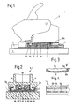
- FIG. 1 shows a safety ski binding according to the invention in longitudinal section and FIG. 2 shows the binding in cross section. 3 and 4, the longitudinal section and the bottom view of the spring cage are shown.
- FIGS. 1 and 2 A safety ski binding is shown in FIGS. 1 and 2.
- a guide rail 2 On the top of a ski 1, a guide rail 2 is fastened by means of screws, not shown, on which a binding body 3 is displaceably guided in the longitudinal direction of the ski 1 and in a manner known per se for adapting the binding to differently long ski boots in the desired position by means of a Adjustment catch 4 can be determined.
- the binding body 3 has a pressing device which consists of two pressing springs 5 in a spring cage 6 having two side walls 6e, and is displaceable against the force of the pressing springs 5 on the guide rail 2, the pressing springs 5 between a shoulder 3a of the binding body 3 and the rear Wall 6a of the spring cage 6 are clamped.
- the spring cage 6 is made of plastic and has in the middle part of its bottom 6b a longitudinal web 6c, which is formed by two elongated recesses 6d in the bottom 6b in a resiliently convex manner.
- the web of the spring cage 6 thus forms a resilient element 6c.
- the side walls 6e of the spring cage 6 come into contact with the binding body 3 along the surface 3b and also push it up until it lies against the rail surfaces 2a and has no more play in the guide rail 2.
- the Binding body 3 pushed up front and back down.
- the binding body 3 is in a somewhat inclined position relative to the guide rail 2, viewed in the longitudinal direction of the ski, the resilient element 6c being deformed. This deformation, however, is negligible compared to the frictional forces that arise during an adjustment of the binding body 3 during ski deflections, so that a compensation of ski deflections can take place practically without negative influences by the spring element 6c.
Landscapes
- Footwear And Its Accessory, Manufacturing Method And Apparatuses (AREA)
Claims (3)
- Fixation de sécurité pour ski, munie d'un corps de fixation qui est mobile dans le sens longitudinal du ski, dans une glissière de guidage, peut être arrêté dans différentes positions, au moyen d'un cran réglable, et est soumis à l'influence d'au moins un ressort de pression agissant dans le sens longitudinal du ski, et pourvu d'un dispositif de compensation d'un jeu présent, dans le sens de la hauteur, entre le corps de fixation et la glissière de guidage, caractérisée par le fait que le ressort de pression (5) est retenu dans une cage (6) de ressort présentant deux parois latérales (6e), et dans ou sur le fond (6b) de laquelle est respectivement prévu un élément (6c) à action élastique vers le bas qui, à l'état soulagé, pousse le corps de fixation (3) vers le haut, contre la glissière de guidage (2), par l'intermédiaire des parois latérales (6e) de la cage (6) de ressort ; et par le fait que, à l'état chargé, c'est-à-dire lorsqu'une chaussure de ski est engagée, le corps de fixation (3) prend par rapport à la glissière de guidage (2), en considérant le sens longitudinal du ski, une position inclinée de l'avant vers l'arrière et ayant pour effet de déformer l'élément élastique (6c).
- Fixation de sécurité pour ski, selon la revendication 1, caractérisée par le fait que la cage (6) de ressort est ménagée d'une seule pièce en un matériau élastique, de préférence une matière plastique, l'élément élastique étant réalisé sous la forme d'une nervure (6c) qui s'étend dans le sens longitudinal, dans la partie centrale du fond (6b), et est convexe vers le bas.
- Fixation de sécurité pour ski, selon la revendication 1, caractérisée par le fait que l'élément élastique est formé par au moins un ressort distinct, prévu à la face inférieure du fond, de préférence par une lame de ressort.
Applications Claiming Priority (2)
| Application Number | Priority Date | Filing Date | Title |
|---|---|---|---|
| AT3423/87 | 1987-12-23 | ||
| AT0342387A AT388877B (de) | 1987-12-23 | 1987-12-23 | Sicherheitsskibindung |
Publications (3)
| Publication Number | Publication Date |
|---|---|
| EP0321687A2 EP0321687A2 (fr) | 1989-06-28 |
| EP0321687A3 EP0321687A3 (en) | 1990-01-03 |
| EP0321687B1 true EP0321687B1 (fr) | 1991-12-27 |
Family
ID=3550297
Family Applications (1)
| Application Number | Title | Priority Date | Filing Date |
|---|---|---|---|
| EP88118465A Expired - Lifetime EP0321687B1 (fr) | 1987-12-23 | 1988-11-05 | Fixation de ski de sécurité |
Country Status (3)
| Country | Link |
|---|---|
| EP (1) | EP0321687B1 (fr) |
| AT (1) | AT388877B (fr) |
| DE (1) | DE3867219D1 (fr) |
Families Citing this family (4)
| Publication number | Priority date | Publication date | Assignee | Title |
|---|---|---|---|---|
| AT395538B (de) * | 1990-10-12 | 1993-01-25 | Tyrolia Freizeitgeraete | Vorrichtung zur laengsverstellung von fersenhaltern |
| AT399287B (de) * | 1992-10-29 | 1995-04-25 | Tyrolia Freizeitgeraete | Sohlenauflageplatte |
| AT399821B (de) * | 1992-10-29 | 1995-07-25 | Tyrolia Freizeitgeraete | Sohlenauflageplatte |
| AT414100B (de) * | 2002-10-28 | 2006-09-15 | Tyrolia Technology Gmbh | In den aufbau eines gleitbrettes, insbesondere eines skis, integrierte führungseinrichtung und gleitbrett, insbesondere ski |
Family Cites Families (4)
| Publication number | Priority date | Publication date | Assignee | Title |
|---|---|---|---|---|
| DE2429610C3 (de) * | 1974-06-20 | 1982-07-22 | Geze Gmbh, 7250 Leonberg | Sicherheitsskibindung |
| FR2454822A1 (fr) * | 1979-04-26 | 1980-11-21 | Salomon & Fils F | Fixation de securite pour ski |
| FR2495479A1 (fr) * | 1980-12-10 | 1982-06-11 | Salomon & Fils F | Dispositif de reglage de la position longitudinale d'une fixation de securite pour ski |
| DE3523058C2 (de) * | 1985-06-27 | 1993-11-04 | Marker Deutschland Gmbh | Laengsverstellbare sicherheits-skibindung |
-
1987
- 1987-12-23 AT AT0342387A patent/AT388877B/de active
-
1988
- 1988-11-05 EP EP88118465A patent/EP0321687B1/fr not_active Expired - Lifetime
- 1988-11-05 DE DE8888118465T patent/DE3867219D1/de not_active Expired - Lifetime
Also Published As
| Publication number | Publication date |
|---|---|
| ATA342387A (de) | 1989-02-15 |
| EP0321687A2 (fr) | 1989-06-28 |
| AT388877B (de) | 1989-09-11 |
| DE3867219D1 (de) | 1992-02-06 |
| EP0321687A3 (en) | 1990-01-03 |
Similar Documents
| Publication | Publication Date | Title |
|---|---|---|
| DE2739207A1 (de) | Skistiefelelement | |
| DE3541079A1 (de) | Reibungsarme selbstsperrende einstelleinrichtung | |
| DD238726A5 (de) | Fuehrungsvorrichtung eines schischuhes, und an diese vorrichtung angepasster schuh und schigrundflaeche | |
| DE2066178C2 (de) | Sicherheitsbindung zur Halterung eines Stiefels auf einem Ski | |
| DE19500268C1 (de) | Höhenverstellvorrichtung für einen Sicherheitsgurt | |
| DD239338A5 (de) | Seitliche fuehrungsvorrichtung eines skieschuhes, und an diese vorrichtungangepasster schuh und langlaufski | |
| DE2448769C2 (de) | Haltevorrichtung für Sicherheitsskibindungen | |
| EP0098515B1 (fr) | Dispositif de réglage en longueur pour fixations de ski | |
| DE4040383C2 (de) | Alpine Sicherheitsskibindung | |
| EP0321687A2 (fr) | Fixation de ski de sécurité | |
| DE2910508A1 (de) | Sicherheitsbindung fuer ski | |
| AT396432B (de) | Skibindungsteil, insbesondere vorderbacken | |
| DE3838586C2 (de) | Seitliche Führungsvorrichtung eines Schuhs auf einem Langlaufski | |
| CH653265A5 (de) | Verstelleinrichtung fuer backen. | |
| DE2600858B2 (de) | Skisicherheitsbindung mit einer mit dem Schuh lösbar verbundenen Trittplatte | |
| AT390887B (de) | Sicherheitsskibindung | |
| DE7723442U1 (de) | Einstellbarer scharnierarm eines tuer- oder moebelscharniers | |
| WO1987007516A2 (fr) | Fixation de securite pour ski | |
| DE3526298A1 (de) | Schuh, insbesondere sportschuh mit austauschbarem laufsohlenteil | |
| AT400404B (de) | Haltevorrichtung für eine skibindung | |
| DE2429608C3 (de) | Sicherheitsskibindung | |
| DE60000602T2 (de) | Vorrichtung zum Stützen des Vorderteiles eines Schuhs auf einem Ski | |
| DE3934877A1 (de) | Bindung zum halten des vorderen endes eines schuhs auf einem langlaufski | |
| DE3717101A1 (de) | Sicherheitsskibindung | |
| DE2637870C3 (de) | Sicherheitsskibindung |
Legal Events
| Date | Code | Title | Description |
|---|---|---|---|
| PUAI | Public reference made under article 153(3) epc to a published international application that has entered the european phase |
Free format text: ORIGINAL CODE: 0009012 |
|
| AK | Designated contracting states |
Kind code of ref document: A2 Designated state(s): CH DE FR LI |
|
| RHK1 | Main classification (correction) |
Ipc: A63C 9/00 |
|
| RIN1 | Information on inventor provided before grant (corrected) |
Inventor name: ERDEI, ROLAND Inventor name: LUSCHNIG, FRANZ Inventor name: STRITZL, KARL Inventor name: WUERTHNER, HUBERT |
|
| PUAL | Search report despatched |
Free format text: ORIGINAL CODE: 0009013 |
|
| AK | Designated contracting states |
Kind code of ref document: A3 Designated state(s): CH DE FR LI |
|
| 17P | Request for examination filed |
Effective date: 19900117 |
|
| 17Q | First examination report despatched |
Effective date: 19910612 |
|
| RAP1 | Party data changed (applicant data changed or rights of an application transferred) |
Owner name: TMC CORPORATION |
|
| GRAA | (expected) grant |
Free format text: ORIGINAL CODE: 0009210 |
|
| AK | Designated contracting states |
Kind code of ref document: B1 Designated state(s): CH DE FR LI |
|
| REF | Corresponds to: |
Ref document number: 3867219 Country of ref document: DE Date of ref document: 19920206 |
|
| ET | Fr: translation filed | ||
| PLBE | No opposition filed within time limit |
Free format text: ORIGINAL CODE: 0009261 |
|
| STAA | Information on the status of an ep patent application or granted ep patent |
Free format text: STATUS: NO OPPOSITION FILED WITHIN TIME LIMIT |
|
| REG | Reference to a national code |
Ref country code: CH Ref legal event code: PUE Owner name: HTM SPORT- UND FREIZEITGERAETE GMBH |
|
| RAP2 | Party data changed (patent owner data changed or rights of a patent transferred) |
Owner name: HTM SPORT- UND FREIZEITGERAETE GESELLSCHAFT M.B.H. |
|
| 26N | No opposition filed | ||
| REG | Reference to a national code |
Ref country code: FR Ref legal event code: TP |
|
| REG | Reference to a national code |
Ref country code: CH Ref legal event code: PFA Free format text: HTM SPORT- UND FREIZEITGERAETE AKTIENGESELLSCHAFT |
|
| REG | Reference to a national code |
Ref country code: FR Ref legal event code: CJ |
|
| PGFP | Annual fee paid to national office [announced via postgrant information from national office to epo] |
Ref country code: FR Payment date: 19941005 Year of fee payment: 7 Ref country code: DE Payment date: 19941005 Year of fee payment: 7 |
|
| PGFP | Annual fee paid to national office [announced via postgrant information from national office to epo] |
Ref country code: CH Payment date: 19941129 Year of fee payment: 7 |
|
| PG25 | Lapsed in a contracting state [announced via postgrant information from national office to epo] |
Ref country code: LI Effective date: 19951130 Ref country code: CH Effective date: 19951130 |
|
| REG | Reference to a national code |
Ref country code: CH Ref legal event code: PL |
|
| PG25 | Lapsed in a contracting state [announced via postgrant information from national office to epo] |
Ref country code: FR Effective date: 19960731 |
|
| PG25 | Lapsed in a contracting state [announced via postgrant information from national office to epo] |
Ref country code: DE Effective date: 19960801 |
|
| REG | Reference to a national code |
Ref country code: FR Ref legal event code: ST |