EP0321712A1 - Appareil pour filtrer une addition d'un réactif - Google Patents
Appareil pour filtrer une addition d'un réactif Download PDFInfo
- Publication number
- EP0321712A1 EP0321712A1 EP88119447A EP88119447A EP0321712A1 EP 0321712 A1 EP0321712 A1 EP 0321712A1 EP 88119447 A EP88119447 A EP 88119447A EP 88119447 A EP88119447 A EP 88119447A EP 0321712 A1 EP0321712 A1 EP 0321712A1
- Authority
- EP
- European Patent Office
- Prior art keywords
- filter
- unit
- pump
- filters
- liquid
- Prior art date
- Legal status (The legal status is an assumption and is not a legal conclusion. Google has not performed a legal analysis and makes no representation as to the accuracy of the status listed.)
- Granted
Links
- 238000001914 filtration Methods 0.000 title description 9
- 239000003153 chemical reaction reagent Substances 0.000 title description 3
- 239000002245 particle Substances 0.000 claims abstract description 50
- 239000007788 liquid Substances 0.000 claims abstract description 40
- 238000004458 analytical method Methods 0.000 claims abstract description 30
- 238000012432 intermediate storage Methods 0.000 claims abstract description 8
- 238000000034 method Methods 0.000 claims description 20
- 238000001514 detection method Methods 0.000 claims description 6
- 238000009826 distribution Methods 0.000 claims description 3
- 238000011068 loading method Methods 0.000 claims description 3
- 230000008859 change Effects 0.000 claims description 2
- 108010076504 Protein Sorting Signals Proteins 0.000 claims 1
- 238000005259 measurement Methods 0.000 description 14
- 239000000243 solution Substances 0.000 description 9
- 230000008569 process Effects 0.000 description 8
- 239000002904 solvent Substances 0.000 description 8
- 230000009747 swallowing Effects 0.000 description 7
- 238000011109 contamination Methods 0.000 description 6
- 230000000694 effects Effects 0.000 description 6
- 239000000463 material Substances 0.000 description 6
- 238000005299 abrasion Methods 0.000 description 3
- 230000008901 benefit Effects 0.000 description 3
- 238000010586 diagram Methods 0.000 description 3
- 239000003085 diluting agent Substances 0.000 description 3
- 238000011275 oncology therapy Methods 0.000 description 3
- 230000006793 arrhythmia Effects 0.000 description 2
- 206010003119 arrhythmia Diseases 0.000 description 2
- 230000015572 biosynthetic process Effects 0.000 description 2
- 239000012141 concentrate Substances 0.000 description 2
- 238000010924 continuous production Methods 0.000 description 2
- 238000009434 installation Methods 0.000 description 2
- 238000007726 management method Methods 0.000 description 2
- 238000012544 monitoring process Methods 0.000 description 2
- 208000000418 Premature Cardiac Complexes Diseases 0.000 description 1
- 238000007792 addition Methods 0.000 description 1
- 238000011166 aliquoting Methods 0.000 description 1
- 238000013459 approach Methods 0.000 description 1
- TZCXTZWJZNENPQ-UHFFFAOYSA-L barium sulfate Chemical compound [Ba+2].[O-]S([O-])(=O)=O TZCXTZWJZNENPQ-UHFFFAOYSA-L 0.000 description 1
- 230000008033 biological extinction Effects 0.000 description 1
- 230000006727 cell loss Effects 0.000 description 1
- 238000002512 chemotherapy Methods 0.000 description 1
- 238000004737 colorimetric analysis Methods 0.000 description 1
- 239000002131 composite material Substances 0.000 description 1
- 230000001276 controlling effect Effects 0.000 description 1
- 230000007797 corrosion Effects 0.000 description 1
- 238000005260 corrosion Methods 0.000 description 1
- 230000007423 decrease Effects 0.000 description 1
- 230000006866 deterioration Effects 0.000 description 1
- 238000003745 diagnosis Methods 0.000 description 1
- 238000010790 dilution Methods 0.000 description 1
- 239000012895 dilution Substances 0.000 description 1
- 208000037265 diseases, disorders, signs and symptoms Diseases 0.000 description 1
- 229940079593 drug Drugs 0.000 description 1
- 239000003814 drug Substances 0.000 description 1
- 230000008030 elimination Effects 0.000 description 1
- 238000003379 elimination reaction Methods 0.000 description 1
- 238000005516 engineering process Methods 0.000 description 1
- 238000011049 filling Methods 0.000 description 1
- 239000006260 foam Substances 0.000 description 1
- 239000011521 glass Substances 0.000 description 1
- 230000005484 gravity Effects 0.000 description 1
- 230000000977 initiatory effect Effects 0.000 description 1
- 239000007791 liquid phase Substances 0.000 description 1
- 238000004519 manufacturing process Methods 0.000 description 1
- 238000000691 measurement method Methods 0.000 description 1
- 230000003287 optical effect Effects 0.000 description 1
- 230000001575 pathological effect Effects 0.000 description 1
- 239000011148 porous material Substances 0.000 description 1
- 238000002360 preparation method Methods 0.000 description 1
- 238000012545 processing Methods 0.000 description 1
- 238000005086 pumping Methods 0.000 description 1
- 230000001105 regulatory effect Effects 0.000 description 1
- 230000000717 retained effect Effects 0.000 description 1
- 230000035945 sensitivity Effects 0.000 description 1
- 239000007787 solid Substances 0.000 description 1
- 238000004611 spectroscopical analysis Methods 0.000 description 1
- 239000000126 substance Substances 0.000 description 1
- 238000012360 testing method Methods 0.000 description 1
- 238000002560 therapeutic procedure Methods 0.000 description 1
- 238000011144 upstream manufacturing Methods 0.000 description 1
- XLYOFNOQVPJJNP-UHFFFAOYSA-N water Substances O XLYOFNOQVPJJNP-UHFFFAOYSA-N 0.000 description 1
Images


Classifications
-
- G—PHYSICS
- G01—MEASURING; TESTING
- G01N—INVESTIGATING OR ANALYSING MATERIALS BY DETERMINING THEIR CHEMICAL OR PHYSICAL PROPERTIES
- G01N15/00—Investigating characteristics of particles; Investigating permeability, pore-volume or surface-area of porous materials
- G01N15/10—Investigating individual particles
- G01N15/14—Optical investigation techniques, e.g. flow cytometry
- G01N15/1404—Handling flow, e.g. hydrodynamic focusing
-
- B—PERFORMING OPERATIONS; TRANSPORTING
- B01—PHYSICAL OR CHEMICAL PROCESSES OR APPARATUS IN GENERAL
- B01D—SEPARATION
- B01D35/00—Filtering devices having features not specifically covered by groups B01D24/00 - B01D33/00, or for applications not specifically covered by groups B01D24/00 - B01D33/00; Auxiliary devices for filtration; Filter housing constructions
- B01D35/12—Devices for taking out of action one or more units of multi- unit filters, e.g. for regeneration
-
- B—PERFORMING OPERATIONS; TRANSPORTING
- B01—PHYSICAL OR CHEMICAL PROCESSES OR APPARATUS IN GENERAL
- B01D—SEPARATION
- B01D37/00—Processes of filtration
- B01D37/04—Controlling the filtration
-
- G—PHYSICS
- G01—MEASURING; TESTING
- G01F—MEASURING VOLUME, VOLUME FLOW, MASS FLOW OR LIQUID LEVEL; METERING BY VOLUME
- G01F23/00—Indicating or measuring liquid level or level of fluent solid material, e.g. indicating in terms of volume or indicating by means of an alarm
-
- Y—GENERAL TAGGING OF NEW TECHNOLOGICAL DEVELOPMENTS; GENERAL TAGGING OF CROSS-SECTIONAL TECHNOLOGIES SPANNING OVER SEVERAL SECTIONS OF THE IPC; TECHNICAL SUBJECTS COVERED BY FORMER USPC CROSS-REFERENCE ART COLLECTIONS [XRACs] AND DIGESTS
- Y10—TECHNICAL SUBJECTS COVERED BY FORMER USPC
- Y10T—TECHNICAL SUBJECTS COVERED BY FORMER US CLASSIFICATION
- Y10T436/00—Chemistry: analytical and immunological testing
- Y10T436/10—Composition for standardization, calibration, simulation, stabilization, preparation or preservation; processes of use in preparation for chemical testing
- Y10T436/101666—Particle count or volume standard or control [e.g., platelet count standards, etc.]
-
- Y—GENERAL TAGGING OF NEW TECHNOLOGICAL DEVELOPMENTS; GENERAL TAGGING OF CROSS-SECTIONAL TECHNOLOGIES SPANNING OVER SEVERAL SECTIONS OF THE IPC; TECHNICAL SUBJECTS COVERED BY FORMER USPC CROSS-REFERENCE ART COLLECTIONS [XRACs] AND DIGESTS
- Y10—TECHNICAL SUBJECTS COVERED BY FORMER USPC
- Y10T—TECHNICAL SUBJECTS COVERED BY FORMER US CLASSIFICATION
- Y10T436/00—Chemistry: analytical and immunological testing
- Y10T436/25—Chemistry: analytical and immunological testing including sample preparation
- Y10T436/25375—Liberation or purification of sample or separation of material from a sample [e.g., filtering, centrifuging, etc.]
Definitions
- the invention is in the field of automated laboratory analysis and relates to a device for fine filtering reagent additions in an automatic analyzer according to the preamble of patent claim 1.
- the reagents used are particle-free or at least low in particles, since foreign particles falsify the counting results, similar to what is known, for example, from color contamination of solvents in colorimetry. If, in order to stick to the example of the colorimetric measurement, the "elimination" of the color contamination by a corrective reference or compensation measurement can still be carried out without much additional effort, then the problem with particle analysis lies on another, much more complex level.
- the particle analysis is usually a real counting process, the particles are recorded individually, whereas an optical measurement (via the statistical mean) only indirectly indicates the content, the amount of a substance in the solution, etc.
- a stand reservoir 1 contains unfiltered or pre-filtered solution or solvent in sufficient quantity, for example for one day of continuous operation. It is assumed that this medium does not meet the purity requirements with regard to particles and that the liquid used must still be prepared for analysis. This is done "on-line” in the subsequent filter device, consisting of the main components 2 filter pump), 3 (filter) and 4 (short-term reservoir), which are integrated in a control circuit via a control S.
- the controllable or regulatable pump unit 2 takes liquid medium from the standing reservoir 1 and pumps it under adequate pressure into a filter unit 3 which contains a filter insert with, for example, submicron pores.
- the liquid applied to the filter is sucked off during filtering, which means that the pump does not press on the filter, but draws the liquid by forming a pressure difference below the filter.
- This has advantages in that the operating pressure limitation on the filter is self-sufficient at approximately 1 at and damage caused by overpressure is excluded.
- this advantage is dispensed with in the proposed solution and the pump power is applied strikes the filter surface directly in the direction of flow. With this measure, it is possible to prevent the smallest particles that arise in the pump, for example due to abrasion, from being flushed directly into the analyzer. Furthermore, foam formation and hollow suction in the liquid medium are avoided, which could lead to aliquoting problems in the downstream short-term reservoir.
- the operational relationship between the pump, its output and filter type, filter area and its resistance, as well as the swallowing characteristics to be set for the short-term reservoir etc. will be discussed further below.
- the short-term reservoir 4 is small-volume and volume-controlled. It can be vented, but is protected against contamination (closed) and has a level detection device S with two sensors L1 for an upper level and L2 for a lower level.
- the short-term reservoir is also easy to maintain; it should be quickly washable, interchangeable if necessary and should not have any contamination points (corners and cracks).
- the analysis device 5 is supplied with solution media from this short-term reservoir.
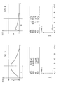
- FIG. 5 shows a general diagram of a particle analysis, in which the frequency H (V) is plotted against the particle volume V.
- Area A is a small particle area in which platelets are of particular interest today, in which However, the area may also cause disturbing particles, as discussed above, to be particularly noticeable and question the uniqueness of the measurement.
- Area B is a frequency range, in which, based on the same example, the smallest amounts of platelets, which are important in cancer therapy, for example, are still used, but in which area (numerically, i.e. based on the count) correspondingly small interference particles are also noticeable do. This stems from the fact that a cell loss caused by cancer therapy (platelet loss) must be recognized if you want to initiate the necessary measures in good time (e.g.
- Figure 6 now shows, together with the two Tables I and II, the example of a bad empty count or a good empty count (Table II), as is the rule when using the filter device according to the invention.
- the poor empty count already shows a high contribution to particles in the very small particle range, so that the sensitivity threshold for the measurement of platelets is undesirably shifted upwards due to this disturbing background. If you look at both Tables I and II, you can see from the "good" empty count (Table I) that an almost tiny particle-free solution is used and the histogram of the subsequent measurement only shows particles that are analytically relevant and allow a good interpretation . With the "bad" empty counting (Table II) one is never sure whether relevant information has just been lost in the display area of the foreign particles. Here at the latest the importance of using particle-free solution media is clear, but you can also see the problems that stand in the way of achieving such a high standard.
- the short-term reservoir In the functional sequence of the overall system, it is assumed that at the exit of the short-term reservoir 4, a sufficiently large volume of liquid can be withdrawn with the shortest possible service life. This happens in portions in a higher work cycle. Based on this, the short-term reservoir should ideally be empty after a liquid withdrawal, but, even in the case of work cycle arrhythmia, it should be sufficiently full again to be able to cover this special requirement. This is opposed by the behavior of the filter unit, which is a flow bottleneck and also has dead times. Thus, the short-term reservoir is designed by a factor greater than 1.0 * deduction volume and a volume differential operation is established which functions as follows.
- swallowing volume of the analyzer contains liquid and the pump is out of operation. Below the level L1, the pump is switched on and freshly filtered liquid flows in during the liquid withdrawal. This applies to all the embodiments shown in FIGS. 1 to 4. The removal speed will generally be higher than the run-on speed, so that the liquid level gradually approaches level L2. If it reaches this, a bypass filter (or more) is automatically switched on in the embodiments according to FIGS. 2 to 4 and the filter output is briefly doubled (multiplied). In this way, a flexible offer in the case of a short-term reservoir volume almost the same as swallowing volume ensures high operational reliability against clock arrhythmias or slight clock deviations aims and at the same time achieves minimal downtimes (only one work cycle).
- the bypass is of course also activated when the filter performance decreases (filter contamination), so that a gradual clogging of the filter is not only detected early enough, but can also be indicated optically and / or acoustically.
- the control signals for this are obtained by comparing the operating times of the master (main filter) and slave (secondary filter). As soon as the slave is used excessively, the master must be replaced.
- the pump continues to fill the short-term reservoir until the liquid level reaches level L2 from below, whereupon the bypass filter unit is switched off and, when level L1 is reached, pump activity is interrupted until the liquid level, is again below the level L1 due to the new removal.
- the short-term reservoir space must be ventilated and vented in all of these processes, which is represented by a vent filter 7.
- the pressure instead of suction operation prevents the formation of bubbles in the drain of the reservoir and the filter throughput can be regulated by controlling the pump pressure accordingly. In this way, the volume balance between removal and supply can be adjusted.
- the filter device can also be adjusted to the cadence of the analysis device. This is important because the proposed filter device is suitable for a plurality of types of apparatus in the field of particle analysis, but also for other applications where inline filtering is important. The device is given this broad suitability in particular by the embodiments just discussed.
- a bypass filter is dispensed with and the level L2 sensor is used to switch on the pump, which does not work when the liquid level comes between the two from above Level is, or the pump switches off after the liquid level reaches level L1 from below and the reservoir is full again.
- This operation can easily be changed over to the more intelligent operation of the first embodiment by using the additional filter unit described above and the correspondingly expanded control circuit S.
- a piston pump K1 / K2 with a scooping volume that is a multiple of the short-term reservoir volume can be used as the pump unit 2 (FIG. 2).
- centrifugal pumps, vane pumps, gear pumps and the like, or rotary pumps for short are also suitable, as the embodiment according to FIG. 3 shows.
- a piston pump has the advantage of simple pump pressure control on the one hand and minimal self-abrasion on the other. The latter is of course essential in the targeted small particle analysis and, last but not least, constant abrasion from the pump unit would put additional strain on the filter unit (s).
- the piston pump is more suitable for intermittent operation than pumps that have to build up the appropriate flow again to achieve the pumping effect (pumps for continuous operation).
- Piston pumps made of glass, which material is generally considered to be corrosion-resistant, are advantageous.
- the piston pump is reversed in accordance with the known procedure. If the reversing and subsequent filling time of the piston also have to be bridged with a very high cadence, the use of a second, reciprocating piston (or pump) is recommended. However, if you do not want such a solution, you resort to a conti pump of the above types by having them pump against a closed valve instead of switching them off.
- a changeover unit 10 for example a reusable valve, is either connected downstream of the filters, as in the example with the piston pumps K1 / K2 (FIG. 2), or upstream of the filters, as in the example with the rotary pump (FIG. 3).
- the reversal takes place by means of the signal S * from the control unit S, which is also responsible for the pump control.
- the signal S * is to be understood as a general, for example composite signal.
- continuous operation can take place in two or more stages of the rotational speed. E.g.
- the filter unit is preferably of rather small volume and the filter surface is chosen to be only large enough that the filter unit can be used independently of a force of gravity. This can be important if, due to a subsequent installation, which is always recommended for old devices, spatial constraints require flexible installation.
- Known filters can be used as filter material. As a rule, usable filter cartridges are likely to be usable almost unchanged, so that we will not describe these filter units in more detail.
- the control unit S has the task of initiating the correct activities of the pump from the level monitoring values. In the simplest case, this would be switching off and on (FIG. 1) and, in the two embodiments according to FIGS. 2 and 3, switching the bypass filter on and off. This also includes the possible reversal when using a piston pump and the control of the reversing elements 10 with which the material path is determined.
- the control unit In addition to the signals from the level sensors L1, L2, the control unit also receives the clock information 5 ⁇ from the analyzer 5 with which the pump pressure and / or the cadence (throughput) are controlled. Another signal path 5 'leads from the analysis unit 5 to the pump unit 2, on which further conditions in the form of signal parameters can be transmitted. In the embodiment according to FIG.
- pressure sensors are provided in front of the filter units, so that in addition to the level signals, pressure signals can also be used to control or regulate the supply of filtered medium.
- the performance of the filter device according to the invention can be flexibly based on the swallowing ability of the consumer device, but this swallowing ability must be communicated to the control device in the correct manner.
- the control device S for the first embodiment houses a display and comparison device for displaying the activity and the comparison result of the operation of the two filter units master and slave. As already mentioned, the state of the filter or filters in the filter units is then concluded from this.
- FIG. 4 now shows a filter device that is managed entirely by digital means. It also shows, better than the other three figures, the overall process sequence. For the sake of clarity, the same reference numbers have been retained as best as possible and only those essential elements shown. These are, counted from top to bottom, a stand reservoir 1 with the medium to be filtered, a controllable or regulatable pump unit 2, a reversing unit 10, which is constructed here as a multiplexer as soon as more than two filter paths are to be implemented. This is followed, always along the material path, optionally by pressure sensors P1, P2, P3 to Pn, with which the back pressure of the downstream filters P1 to Pn can be measured.
- the intermediate storage unit is connected to the particle analysis device 5, which is signal-related to a digital control processor 51 via a bus, which is symbolically represented here.
- processor 51 is a PC-level computer; but single-board processors specially tailored to this application are also suitable.
- a central data bus 11 leads from the processor 51 to all controllable device parts, all of which, of course, must be addressable accordingly.
- the configuration shown here is not the only possible one, but it is the simplest in terms of the complexity of the process.
- the control unit S receives all sensor signals. Here it is the level and pressure status signals.
- the received signals are brought to the computer 51 via the bus 12 and processed there together with signals from the analyzer 5 to control parameters and addresses to which the specific effect is to be given, which are then sent via the system bus 11 to the actuator / pump 2 (bus 14) and distributor 10 (bus 13).
- the distributor 10 which works as a multiplexer, can be brought into the desired type of actuation with its own subroutine.
- the pump unit 2 consists of a speed-controlled rotary pump (it can also be a multi-stage pump) which offers the multiplexer / distributor 10 the desired pump pressure for switching through to one or two or more filters almost immediately
- the following operating variants are possible: - All filters are applied to one another, the buffer unit 4 will fill up quickly. In this short time, however, the pressures build up at different speeds depending on their condition, which is registered by the pressure sensors. A filter path with medium pressure rise behavior is selected for subsequent operation. Criterion for this, filters with rapid pressure build-up can be blocked (only a short operating time possible), filters with slow pressure build-up are still fresh (long operating times possible).
- the filter with the fastest pressure rise behavior is added to the filter with medium pressure rise behavior. If the media supply rises above the required swallowing capacity of the analyzer above a specified limit value, this filter is operated until the limit value is undershot and then reported by the computer (as blocked) for replacement. In this way, expensive filter units in particular can be optimally used.
- the remaining filters are used in a kind of test runs at predetermined time intervals in order to check their functionality again and again. From the earlier pressure rise behavior, which advantageously remains stored, derive a possible deterioration of the stance behavior and the affected filter is then used earlier than a filter with better stance behavior.
- the computer is also able to output this behavior in individual filter protocols.
- the detection parameters for a filter are derived, among other things. from the pressure rise behavior.
- the data records for a filter can be offered from a "library" stored in the machine via a menu on the screen and selected from there. The assignment of data to a filter used simplifies monitoring as to whether the correct filter is used or not.
- the methods and devices discussed here allow the detection of exhausted filters, new filters, used and soon used filters, but also the service life behavior can be determined. Furthermore, the parallelism that provides information and security (redundancy) can be used at any time to everyone existing swallowing capacity of one or more devices to serve immediately. The information can be used for the overall management of the filter system, which shows which filters need to be replaced, which filters should be put into operation earlier than others and, last but not least, which filter became unusable during its service life and has to be replaced despite being used little. It is clear that this will also facilitate the scheduling for several plants. The use of an incorrect filter type can also be determined, which further increases safety.
- the specified method is suitable for loading one or more automated analyzers with filtered media.
- a filter can be selected for the operation from the entire filter set with an average pressure rise behavior against the pump pressure and the filter with the fastest pressure rise behavior against the pump pressure for operation.
- the filter with the fastest pressure rise behavior is the "most exhausted or blocked" of the whole battery, so it can be used optimally or even to the maximum.
- a filter with a pressure rise content that is higher than a certain threshold value can be eliminated from (main) operation and another filter with a lower pressure rise content can be put into operation.
- Filters with a behavior that is unspecific based on the specific pressure rise behavior of the filter type used can be eliminated and / or displayed and / or logged by the company. From a procedural point of view, there is a great deal of leeway here that can be used through the necessary measures.
Landscapes
- Chemical & Material Sciences (AREA)
- Chemical Kinetics & Catalysis (AREA)
- Physics & Mathematics (AREA)
- General Physics & Mathematics (AREA)
- Analytical Chemistry (AREA)
- Dispersion Chemistry (AREA)
- Health & Medical Sciences (AREA)
- Life Sciences & Earth Sciences (AREA)
- Fluid Mechanics (AREA)
- Biochemistry (AREA)
- General Health & Medical Sciences (AREA)
- Immunology (AREA)
- Pathology (AREA)
- Sampling And Sample Adjustment (AREA)
- Filtration Of Liquid (AREA)
- Investigating Or Analysing Biological Materials (AREA)
- Networks Using Active Elements (AREA)
Priority Applications (1)
| Application Number | Priority Date | Filing Date | Title |
|---|---|---|---|
| AT88119447T ATE74789T1 (de) | 1987-12-23 | 1988-11-23 | Vorrichtung zum filtrieren einer reagenszugabe. |
Applications Claiming Priority (2)
| Application Number | Priority Date | Filing Date | Title |
|---|---|---|---|
| CH501687 | 1987-12-23 | ||
| CH5016/87 | 1987-12-23 |
Publications (2)
| Publication Number | Publication Date |
|---|---|
| EP0321712A1 true EP0321712A1 (fr) | 1989-06-28 |
| EP0321712B1 EP0321712B1 (fr) | 1992-04-15 |
Family
ID=4286484
Family Applications (1)
| Application Number | Title | Priority Date | Filing Date |
|---|---|---|---|
| EP88119447A Expired - Lifetime EP0321712B1 (fr) | 1987-12-23 | 1988-11-23 | Appareil pour filtrer une addition d'un réactif |
Country Status (6)
| Country | Link |
|---|---|
| US (1) | US5104553A (fr) |
| EP (1) | EP0321712B1 (fr) |
| JP (1) | JPH01203014A (fr) |
| AT (1) | ATE74789T1 (fr) |
| CA (1) | CA1328229C (fr) |
| DE (1) | DE3870185D1 (fr) |
Families Citing this family (11)
| Publication number | Priority date | Publication date | Assignee | Title |
|---|---|---|---|---|
| US5230793A (en) * | 1991-09-25 | 1993-07-27 | Barnes International, Inc. | Chip filtration and removal system |
| US5209822A (en) * | 1991-10-21 | 1993-05-11 | Ingersoll-Rand Company | Method for controlling liquid level in a knot drainer |
| US5631460A (en) * | 1995-01-24 | 1997-05-20 | Satake Usa Inc. | Sorting machine using dual frequency optical detectors |
| CA2543385C (fr) * | 2005-04-14 | 2015-02-03 | Superior Plus Inc. | Echantillons de boue de conditionnement pour analyse instrumentale quantitative |
| CA2639110C (fr) * | 2007-08-27 | 2013-12-10 | Culligan International Company | Salometre et ensemble de capteurs de debit |
| US8469916B2 (en) * | 2011-02-28 | 2013-06-25 | Fenwal, Inc. | Systems and methods for single needle continuous plasma processing |
| US9804109B2 (en) * | 2012-05-10 | 2017-10-31 | Design West Technologies, Inc. | System and method for chemical and/or biological detection |
| EP3478745B1 (fr) * | 2016-06-30 | 2021-02-24 | Covestro LLC | Procédés et systèmes pour éliminer l'eau et le sel d'un polyol de polyéther neutralisé |
| US10330617B2 (en) | 2017-01-10 | 2019-06-25 | Design West Technologies, Inc. | Wearable sensor badge for toxic industrial chemicals |
| ES3003758T3 (en) * | 2019-10-18 | 2025-03-11 | Hoffmann La Roche | Techniques for checking state of analyzers |
| JP2026016968A (ja) * | 2024-07-23 | 2026-02-04 | メディカテック株式会社 | 吸引濾過装置 |
Citations (3)
| Publication number | Priority date | Publication date | Assignee | Title |
|---|---|---|---|---|
| FR1044781A (fr) * | 1951-06-14 | 1953-11-20 | Chabal Et Cie C | Station de traitement d'eau à réglage automatique recevant des débits d'eau à traiter susceptibles d'être différents des débits d'eau traitée soutirés |
| US3143393A (en) * | 1959-06-18 | 1964-08-04 | Luc Donald De Seguin Des Hons | Apparatus for automatically performing chemical operations and similar or related operations |
| EP0107333A2 (fr) * | 1982-09-30 | 1984-05-02 | TECHNICON INSTRUMENTS CORPORATION (a New York corporation) | Appareil et méthode pour alimenter une cellule analytique à écoulement en liquide d'échantillon et liquide d'enveloppe |
Family Cites Families (2)
| Publication number | Priority date | Publication date | Assignee | Title |
|---|---|---|---|---|
| US4086165A (en) * | 1974-07-25 | 1978-04-25 | Augusto Formenti | Liquid-treatment system |
| US3957637A (en) * | 1974-08-23 | 1976-05-18 | The Taulman Company | Filtration system and flow control method therefor |
-
1988
- 1988-11-23 EP EP88119447A patent/EP0321712B1/fr not_active Expired - Lifetime
- 1988-11-23 DE DE8888119447T patent/DE3870185D1/de not_active Expired - Lifetime
- 1988-11-23 AT AT88119447T patent/ATE74789T1/de active
- 1988-12-19 US US07/286,563 patent/US5104553A/en not_active Expired - Fee Related
- 1988-12-20 CA CA000586469A patent/CA1328229C/fr not_active Expired - Fee Related
- 1988-12-22 JP JP63322234A patent/JPH01203014A/ja active Pending
Patent Citations (3)
| Publication number | Priority date | Publication date | Assignee | Title |
|---|---|---|---|---|
| FR1044781A (fr) * | 1951-06-14 | 1953-11-20 | Chabal Et Cie C | Station de traitement d'eau à réglage automatique recevant des débits d'eau à traiter susceptibles d'être différents des débits d'eau traitée soutirés |
| US3143393A (en) * | 1959-06-18 | 1964-08-04 | Luc Donald De Seguin Des Hons | Apparatus for automatically performing chemical operations and similar or related operations |
| EP0107333A2 (fr) * | 1982-09-30 | 1984-05-02 | TECHNICON INSTRUMENTS CORPORATION (a New York corporation) | Appareil et méthode pour alimenter une cellule analytique à écoulement en liquide d'échantillon et liquide d'enveloppe |
Also Published As
| Publication number | Publication date |
|---|---|
| EP0321712B1 (fr) | 1992-04-15 |
| JPH01203014A (ja) | 1989-08-15 |
| DE3870185D1 (de) | 1992-05-21 |
| US5104553A (en) | 1992-04-14 |
| CA1328229C (fr) | 1994-04-05 |
| ATE74789T1 (de) | 1992-05-15 |
Similar Documents
| Publication | Publication Date | Title |
|---|---|---|
| DE3689533T3 (de) | Plasmaphorese-verfahren | |
| EP0321712B1 (fr) | Appareil pour filtrer une addition d'un réactif | |
| DE69628824T2 (de) | Filtrationskontroll- und regulationssystem | |
| DE3752055T2 (de) | Kalibrierung mehrerer Pumpen eines Flüssigkeitsströmungssystems | |
| DE60127482T2 (de) | Wasserreinigung System mit Messung und Steuerung der Abgabe | |
| DE3504955C2 (fr) | ||
| DE3831771C2 (fr) | ||
| DE1773226A1 (de) | Analysiergeraet fuer Blut od.dgl.zur selbsttaetigen Ermittlung bestimmter Parameter | |
| EP0166920A1 (fr) | Dispositif pour enlever un liquide dialysant traité et non-traité et/ou du sang d'un dialyseur | |
| EP3810747B1 (fr) | Système de traitement modulaire et procédé de montage modulaire d'un système de traitement | |
| DE2616783C3 (de) | Vorrichtung zum Bestimmen des Mahlungsgrades von Papierstoff | |
| DE69221541T2 (de) | Verfahren und Vorrichtung zum automatischer Analysieren von Teilchen in einer Flüssigkeit | |
| DE69032577T2 (de) | Verfahren und Vorrichtung für kontrollierte Instrumentation von Teilchen mittels einer Filtervorrichtung | |
| DE2811972C2 (de) | Halbautomatische Vorrichtung zum Zählen von Blutzellen | |
| EP0355631B1 (fr) | Dispositif pour le traitement du liquide d'usinage d'une machine d'électro-érosion | |
| DE20305506U1 (de) | Vorrichtung zur automatischen Filtration | |
| EP2265939B1 (fr) | Procédé et dispositif de mesure pour déterminer la teneur d'un milieu liquide en au moins un adjuvant de filtrage | |
| EP0353422B1 (fr) | Procédé et appareil de filtration | |
| DE2450609A1 (de) | Vorrichtung zur automatischen bestimmung von proteinen | |
| DE60303051T2 (de) | Filter mit integrierter kontrolle des probenvolumens | |
| DE3220327A1 (de) | Verfahren zum messen der ionenkonzentration einer probe | |
| EP3665465B1 (fr) | Cellule de dialyse permettant la préparation d'éprouvettes pour chromatographie à échange d'ions | |
| EP3559196A1 (fr) | Régulation de la concentration dans le flux tangentiel lors de la filtration sur membrane de la bière | |
| DE4012104A1 (de) | Zusatzeinrichtung fuer separator | |
| DE2601732B2 (de) | Verfahren zum Spulen der Filterkammern eines Filteraggregates und Filteraggregat zur Durchführung dieses Verfahrens |
Legal Events
| Date | Code | Title | Description |
|---|---|---|---|
| PUAI | Public reference made under article 153(3) epc to a published international application that has entered the european phase |
Free format text: ORIGINAL CODE: 0009012 |
|
| AK | Designated contracting states |
Kind code of ref document: A1 Designated state(s): AT BE CH DE FR GB IT LI NL SE |
|
| 17P | Request for examination filed |
Effective date: 19890904 |
|
| RAP1 | Party data changed (applicant data changed or rights of an application transferred) |
Owner name: OERLIKON-CONTRAVES AG |
|
| 17Q | First examination report despatched |
Effective date: 19910515 |
|
| GRAA | (expected) grant |
Free format text: ORIGINAL CODE: 0009210 |
|
| AK | Designated contracting states |
Kind code of ref document: B1 Designated state(s): AT BE CH DE FR GB IT LI NL SE |
|
| PG25 | Lapsed in a contracting state [announced via postgrant information from national office to epo] |
Ref country code: IT Free format text: LAPSE BECAUSE OF FAILURE TO SUBMIT A TRANSLATION OF THE DESCRIPTION OR TO PAY THE FEE WITHIN THE PRESCRIBED TIME-LIMIT;WARNING: LAPSES OF ITALIAN PATENTS WITH EFFECTIVE DATE BEFORE 2007 MAY HAVE OCCURRED AT ANY TIME BEFORE 2007. THE CORRECT EFFECTIVE DATE MAY BE DIFFERENT FROM THE ONE RECORDED. Effective date: 19920415 Ref country code: BE Effective date: 19920415 Ref country code: SE Effective date: 19920415 Ref country code: NL Effective date: 19920415 |
|
| REF | Corresponds to: |
Ref document number: 74789 Country of ref document: AT Date of ref document: 19920515 Kind code of ref document: T |
|
| REF | Corresponds to: |
Ref document number: 3870185 Country of ref document: DE Date of ref document: 19920521 |
|
| GBT | Gb: translation of ep patent filed (gb section 77(6)(a)/1977) | ||
| ET | Fr: translation filed | ||
| NLV1 | Nl: lapsed or annulled due to failure to fulfill the requirements of art. 29p and 29m of the patents act | ||
| PLBE | No opposition filed within time limit |
Free format text: ORIGINAL CODE: 0009261 |
|
| STAA | Information on the status of an ep patent application or granted ep patent |
Free format text: STATUS: NO OPPOSITION FILED WITHIN TIME LIMIT |
|
| 26N | No opposition filed | ||
| PGFP | Annual fee paid to national office [announced via postgrant information from national office to epo] |
Ref country code: FR Payment date: 19941007 Year of fee payment: 7 |
|
| PGFP | Annual fee paid to national office [announced via postgrant information from national office to epo] |
Ref country code: AT Payment date: 19941013 Year of fee payment: 7 |
|
| PGFP | Annual fee paid to national office [announced via postgrant information from national office to epo] |
Ref country code: GB Payment date: 19941014 Year of fee payment: 7 |
|
| PGFP | Annual fee paid to national office [announced via postgrant information from national office to epo] |
Ref country code: DE Payment date: 19941024 Year of fee payment: 7 |
|
| PGFP | Annual fee paid to national office [announced via postgrant information from national office to epo] |
Ref country code: CH Payment date: 19941025 Year of fee payment: 7 |
|
| PG25 | Lapsed in a contracting state [announced via postgrant information from national office to epo] |
Ref country code: GB Effective date: 19951123 Ref country code: AT Effective date: 19951123 |
|
| PG25 | Lapsed in a contracting state [announced via postgrant information from national office to epo] |
Ref country code: LI Effective date: 19951130 Ref country code: CH Effective date: 19951130 |
|
| REG | Reference to a national code |
Ref country code: CH Ref legal event code: PL |
|
| GBPC | Gb: european patent ceased through non-payment of renewal fee |
Effective date: 19951123 |
|
| PG25 | Lapsed in a contracting state [announced via postgrant information from national office to epo] |
Ref country code: FR Effective date: 19960731 |
|
| PG25 | Lapsed in a contracting state [announced via postgrant information from national office to epo] |
Ref country code: DE Effective date: 19960801 |
|
| REG | Reference to a national code |
Ref country code: FR Ref legal event code: ST |