EP0321743A2 - Réglette de raccordement pour lignes électriques de départ et d'arrivée - Google Patents
Réglette de raccordement pour lignes électriques de départ et d'arrivée Download PDFInfo
- Publication number
- EP0321743A2 EP0321743A2 EP88119912A EP88119912A EP0321743A2 EP 0321743 A2 EP0321743 A2 EP 0321743A2 EP 88119912 A EP88119912 A EP 88119912A EP 88119912 A EP88119912 A EP 88119912A EP 0321743 A2 EP0321743 A2 EP 0321743A2
- Authority
- EP
- European Patent Office
- Prior art keywords
- lines
- connection
- terminal block
- connection elements
- incoming
- Prior art date
- Legal status (The legal status is an assumption and is not a legal conclusion. Google has not performed a legal analysis and makes no representation as to the accuracy of the status listed.)
- Granted
Links
- 230000001681 protective effect Effects 0.000 abstract description 3
- 238000006073 displacement reaction Methods 0.000 description 3
- 238000009413 insulation Methods 0.000 description 3
Images
Classifications
-
- H—ELECTRICITY
- H04—ELECTRIC COMMUNICATION TECHNIQUE
- H04Q—SELECTING
- H04Q1/00—Details of selecting apparatus or arrangements
- H04Q1/02—Constructional details
- H04Q1/14—Distribution frames
- H04Q1/141—Details of connexions between cable and distribution frame
-
- H—ELECTRICITY
- H01—ELECTRIC ELEMENTS
- H01R—ELECTRICALLY-CONDUCTIVE CONNECTIONS; STRUCTURAL ASSOCIATIONS OF A PLURALITY OF MUTUALLY-INSULATED ELECTRICAL CONNECTING ELEMENTS; COUPLING DEVICES; CURRENT COLLECTORS
- H01R9/00—Structural associations of a plurality of mutually-insulated electrical connecting elements, e.g. terminal strips or terminal blocks; Terminals or binding posts mounted upon a base or in a case; Bases therefor
- H01R9/22—Bases, e.g. strip, block, panel
- H01R9/24—Terminal blocks
- H01R9/2416—Means for guiding or retaining wires or cables connected to terminal blocks
-
- H—ELECTRICITY
- H05—ELECTRIC TECHNIQUES NOT OTHERWISE PROVIDED FOR
- H05K—PRINTED CIRCUITS; CASINGS OR CONSTRUCTIONAL DETAILS OF ELECTRIC APPARATUS; MANUFACTURE OF ASSEMBLAGES OF ELECTRICAL COMPONENTS
- H05K7/00—Constructional details common to different types of electric apparatus
- H05K7/18—Construction of rack or frame
- H05K7/186—Construction of rack or frame for supporting telecommunication equipment
-
- H—ELECTRICITY
- H01—ELECTRIC ELEMENTS
- H01R—ELECTRICALLY-CONDUCTIVE CONNECTIONS; STRUCTURAL ASSOCIATIONS OF A PLURALITY OF MUTUALLY-INSULATED ELECTRICAL CONNECTING ELEMENTS; COUPLING DEVICES; CURRENT COLLECTORS
- H01R4/00—Electrically-conductive connections between two or more conductive members in direct contact, i.e. touching one another; Means for effecting or maintaining such contact; Electrically-conductive connections having two or more spaced connecting locations for conductors and using contact members penetrating insulation
- H01R4/24—Connections using contact members penetrating or cutting insulation or cable strands
- H01R4/2416—Connections using contact members penetrating or cutting insulation or cable strands the contact members having insulation-cutting edges, e.g. of tuning fork type
- H01R4/242—Connections using contact members penetrating or cutting insulation or cable strands the contact members having insulation-cutting edges, e.g. of tuning fork type the contact members being plates having a single slot
Definitions
- the invention relates to a terminal block with two rows of connection elements each for incoming and outgoing electrical lines, in particular telephone systems.
- Such a terminal block is such.
- B. become known from DE-0S 27 25 551.
- the connection elements then point in the same direction and are embedded in an insulating body of the connection strip.
- the connecting elements are designed as insulation displacement terminals, the contact points of which lie in one plane. That is, the incoming and outgoing lines are pressed from the same side into the clamping slots of the insulation displacement terminals. The lines are led away from the connection points via the adjacent side edges of the terminal block along the adjoining side surfaces of the contact elements.
- Such terminal strips are such.
- the lines coming from the office are combined in cables and connected to a number of the connection elements.
- the outgoing lines are connected to the other row of connection elements.
- the two rows of connection elements are connected to one another in one piece via a connecting section.
- the outgoing lines are jumper wires that lead to the subscriber lines. This means that these lines must be accessible for wiring changes even after the connection strips have been installed.
- the outgoing lines are therefore routed away via the narrow end faces of the terminal block.
- the lines arriving from cables are brought to the connection elements from the underside facing away from the connection points.
- the invention has for its object to line up the terminal strips as closely as possible and to facilitate the connection of the jumper wires.
- connection rows are used to the maximum.
- the terminal strips can now be lined up with a small lateral distance.
- the incoming lines are fixed to the last connection strip before the next connection strip is attached.
- plug contact points between the rows of connection elements e.g. to be provided for protective plugs that require an appropriate space.
- a corresponding free space must also be created for the attachment of the wiring tools.
- the channel-like wiring space leading to the end faces of the connection strip lies between the two connection elements. This means that the jumper wires are connected to the connection elements from the same side. Since the terminal strips are usually arranged vertically one above the other, the protruding ends hang downwards, which increases clarity and facilitates connection.
- the connecting tool is held in the same position on both rows of connecting elements. The protruding wire ends fall down unhindered after cutting.
- the channel-like wiring space for the outgoing lines can be kept particularly wide.
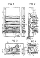
- Figures 1, 2 and 3 show three different side views of a distributor block with connecting strips lined up for incoming and outgoing lines.
- Figure 4 shows a cross section through a terminal block.
- terminal strips 1 for electrical lines are fastened in a row on the longitudinal side to a U-shaped support plate.
- Electrical lines 4 arriving from a cable 3 are brought between the connection strips 1 and the base section of the carrier plate 2 through wire guide eyelets 5, 6 to a number of connection points of the connection strips 1.
- Outgoing lines 7 in the form of jumper wires are connected to a second row of connection points of the terminal strips 1. From there, they lead via a channel-like wiring space 8 of the distributor strip 1 to the end faces thereof, from where they are led to other connection strips.
- U-shaped bent contact parts 9 form the connection points for the incoming lines 4 and the outgoing lines 7 at the ends of their side legs.
- Resilient tabs as contact springs 10 are bent up from the base section of the contact parts 9. Between these pin-shaped connector devices 11 z. B. a protective plug can be inserted contacting.
- the contact springs 10 are shifted towards the side legs for the incoming lines 4, so that the distance between the contact springs 10 and the side legs for the outgoing lines 7 increases accordingly.
- the deep recess between them forms the channel-like wiring space 8, which runs continuously from one to the other end face of the terminal block 1.
- the wiring space is covered on both ends by slotted tabs 12, which represent a guide.
- the incoming lines 4 are connected from the outside of the terminal block 1 to the contact pieces 9.
- the outgoing lines 7 are led from the end faces of the terminal block 1 through the wiring space 8 to the individual contact points and thus from the inside to the Side legs of the contact pieces 9 brought up.
- These form connection elements 14, 13 in the form of insulation displacement terminals. The incoming and outgoing lines 4, 7 are pressed into them from above and contacted thereby.
Landscapes
- Engineering & Computer Science (AREA)
- Computer Networks & Wireless Communication (AREA)
- Microelectronics & Electronic Packaging (AREA)
- Insulated Conductors (AREA)
- Mobile Radio Communication Systems (AREA)
- Details Of Connecting Devices For Male And Female Coupling (AREA)
- Communication Cables (AREA)
- Coupling Device And Connection With Printed Circuit (AREA)
- Connections Effected By Soldering, Adhesion, Or Permanent Deformation (AREA)
- Multi-Conductor Connections (AREA)
- Connections By Means Of Piercing Elements, Nuts, Or Screws (AREA)
- Connections Arranged To Contact A Plurality Of Conductors (AREA)
- Interface Circuits In Exchanges (AREA)
- Cable Accessories (AREA)
- Monitoring And Testing Of Exchanges (AREA)
- Details Of Indoor Wiring (AREA)
Applications Claiming Priority (2)
| Application Number | Priority Date | Filing Date | Title |
|---|---|---|---|
| DE8716919U | 1987-12-23 | ||
| DE8716919U DE8716919U1 (de) | 1987-12-23 | 1987-12-23 | Anschlußleiste für ankommende und abgehende elektrische Leitungen |
Publications (3)
| Publication Number | Publication Date |
|---|---|
| EP0321743A2 true EP0321743A2 (fr) | 1989-06-28 |
| EP0321743A3 EP0321743A3 (en) | 1990-05-23 |
| EP0321743B1 EP0321743B1 (fr) | 1996-02-28 |
Family
ID=6815435
Family Applications (1)
| Application Number | Title | Priority Date | Filing Date |
|---|---|---|---|
| EP88119912A Expired - Lifetime EP0321743B1 (fr) | 1987-12-23 | 1988-11-29 | Réglette de raccordement pour lignes électriques de départ et d'arrivée |
Country Status (6)
| Country | Link |
|---|---|
| EP (1) | EP0321743B1 (fr) |
| AT (1) | ATE134800T1 (fr) |
| AU (1) | AU618053B2 (fr) |
| DE (2) | DE8716919U1 (fr) |
| FI (1) | FI104036B (fr) |
| NO (1) | NO175447C (fr) |
Cited By (5)
| Publication number | Priority date | Publication date | Assignee | Title |
|---|---|---|---|---|
| EP0414043A1 (fr) * | 1989-08-21 | 1991-02-27 | Siemens Aktiengesellschaft | Bloc de distribution pour une installation de télécommunication |
| FR2679392A1 (fr) * | 1991-07-19 | 1993-01-22 | Mars Actel | Dispositif de stockage et de separation de conducteurs. |
| DE4315681C1 (de) * | 1993-05-05 | 1994-11-24 | Krone Ag | Kabelverzweiger |
| DE19816678C1 (de) * | 1998-04-15 | 2000-01-20 | Quante Ag | Anschlußleiste der Telekommunikationstechnik |
| RU188344U1 (ru) * | 2018-10-19 | 2019-04-09 | Общество с ограниченной ответственностью "Квиттер" | Щиток-бокс вводной для кабеля в опоры освещения |
Families Citing this family (3)
| Publication number | Priority date | Publication date | Assignee | Title |
|---|---|---|---|---|
| DE8716918U1 (de) * | 1987-12-23 | 1988-02-18 | Siemens AG, 1000 Berlin und 8000 München | Einrichtung zum Anschließen und Verbinden von elektrischen Leitungen |
| DE4042249A1 (de) * | 1990-12-31 | 1992-07-02 | Quante Ag | Anschluss- und trennleistenanordnung sowie befestigungsklammer hierfuer |
| US5575689A (en) * | 1995-05-17 | 1996-11-19 | Lucent Technologies Inc. | Connector modules |
Family Cites Families (4)
| Publication number | Priority date | Publication date | Assignee | Title |
|---|---|---|---|---|
| DE361223C (de) * | 1921-04-12 | 1922-10-12 | Paul Warg | Notenband fuer pneumatische Spielwerke |
| FR2286520A1 (fr) * | 1974-09-30 | 1976-04-23 | Reliable Electric Co | Bloc de raccordement notamment pour repartiteur telephonique |
| DE3614063C3 (de) * | 1986-04-23 | 1994-02-24 | Krone Ag | Verteilereinrichtung, insbesondere für den Hauptverteiler von Fernsprechanlagen |
| DE3621223A1 (de) * | 1986-06-25 | 1988-01-07 | Siemens Ag | Anschlussleiste fuer elektrische leitungen |
-
1987
- 1987-12-23 DE DE8716919U patent/DE8716919U1/de not_active Expired
-
1988
- 1988-11-29 DE DE3855041T patent/DE3855041D1/de not_active Expired - Fee Related
- 1988-11-29 AT AT88119912T patent/ATE134800T1/de not_active IP Right Cessation
- 1988-11-29 EP EP88119912A patent/EP0321743B1/fr not_active Expired - Lifetime
- 1988-12-22 FI FI885948A patent/FI104036B/fi not_active IP Right Cessation
- 1988-12-22 AU AU27525/88A patent/AU618053B2/en not_active Ceased
- 1988-12-23 NO NO885740A patent/NO175447C/no unknown
Cited By (6)
| Publication number | Priority date | Publication date | Assignee | Title |
|---|---|---|---|---|
| EP0414043A1 (fr) * | 1989-08-21 | 1991-02-27 | Siemens Aktiengesellschaft | Bloc de distribution pour une installation de télécommunication |
| FR2679392A1 (fr) * | 1991-07-19 | 1993-01-22 | Mars Actel | Dispositif de stockage et de separation de conducteurs. |
| EP0526303A1 (fr) * | 1991-07-19 | 1993-02-03 | Alcatel Cable Interface | Dispositif de stockage et de séparation de conducteurs |
| DE4315681C1 (de) * | 1993-05-05 | 1994-11-24 | Krone Ag | Kabelverzweiger |
| DE19816678C1 (de) * | 1998-04-15 | 2000-01-20 | Quante Ag | Anschlußleiste der Telekommunikationstechnik |
| RU188344U1 (ru) * | 2018-10-19 | 2019-04-09 | Общество с ограниченной ответственностью "Квиттер" | Щиток-бокс вводной для кабеля в опоры освещения |
Also Published As
| Publication number | Publication date |
|---|---|
| AU618053B2 (en) | 1991-12-12 |
| AU2752588A (en) | 1989-06-29 |
| FI885948L (fi) | 1989-06-24 |
| NO885740D0 (no) | 1988-12-23 |
| DE3855041D1 (de) | 1996-04-04 |
| FI104036B1 (fi) | 1999-10-29 |
| ATE134800T1 (de) | 1996-03-15 |
| NO885740L (no) | 1989-06-26 |
| FI104036B (fi) | 1999-10-29 |
| DE8716919U1 (de) | 1988-02-18 |
| NO175447B (no) | 1994-07-04 |
| EP0321743B1 (fr) | 1996-02-28 |
| NO175447C (no) | 1994-10-12 |
| EP0321743A3 (en) | 1990-05-23 |
Similar Documents
| Publication | Publication Date | Title |
|---|---|---|
| DE3710896C2 (fr) | ||
| EP0766482A2 (fr) | Dispositif de distribution pour la technique de télécommuication et de données | |
| DE19617114C2 (de) | Erdungsmodul | |
| DE102007032578A1 (de) | Anschlussmodul für die Telekommunikations- und Datentechnik | |
| DE2048104A1 (de) | Verteilerleiste für elektrische Anlagen, insbesondere Fernsprechanlagen | |
| EP0321743B1 (fr) | Réglette de raccordement pour lignes électriques de départ et d'arrivée | |
| DE3730662C2 (fr) | ||
| EP0230537B1 (fr) | Barrette à bornes ainsi qu'un dispositif de connexion avec une de ces barrettes à bornes | |
| EP0667650B1 (fr) | Système de connexion modulaire | |
| EP0180000B1 (fr) | Dispositif à coupure comportant une pluralité de bornes à connexion sans dénudage de conducteurs électriques | |
| DE3927573C1 (fr) | ||
| DE60108218T2 (de) | Anschlussleiste für verknüpfte Leitungen | |
| DE19537529C1 (de) | Verteilerleiste für die Telekommunikations- und Datentechnik | |
| DE2529258A1 (de) | Kabelbaum | |
| EP4038693B1 (fr) | Unité de raccordement dotée d'éléments d'actionnement et d'ouvertures de raccordement de conducteur agencés en deux rangées | |
| EP0365780A2 (fr) | Dispositif de raccordement pour la commutation ou la disconnexion de voies de ligne dans des centraux téléphoniques | |
| EP1166413A1 (fr) | Groupe d'appareils de commutation comportant un systeme de barres de distribution pourvu d'un encapsulage d'isolation | |
| DE102015110059A1 (de) | Steckverbinder und Tragschienenprofil | |
| DE2719269A1 (de) | Als gemeinsame betriebserde fuer die erdtasten mehrerer amtsberechtigter nebenstellen ausgebildete rangierleiste | |
| EP2057717B1 (fr) | Dispositif de répartition d'une installation de télécommunication, dispositif de réception d'un tel dispositif de répartition ainsi que fiche de connexion | |
| EP0405336A2 (fr) | Dispositif de distribution pour installations de télécommunication | |
| DE2643186B1 (de) | Verteilerelement fuer fernmeldevermittlungsanlagen | |
| EP0632527A2 (fr) | Module de connexion | |
| EP0966844A2 (fr) | Dispositif de distribution avec composants de raccordement disposes en rangees les uns a cote des autres sous forme de blocs | |
| EP0865127B1 (fr) | Système de distribution avec un élément de distance |
Legal Events
| Date | Code | Title | Description |
|---|---|---|---|
| PUAI | Public reference made under article 153(3) epc to a published international application that has entered the european phase |
Free format text: ORIGINAL CODE: 0009012 |
|
| AK | Designated contracting states |
Kind code of ref document: A2 Designated state(s): AT BE CH DE FR GB LI NL |
|
| PUAL | Search report despatched |
Free format text: ORIGINAL CODE: 0009013 |
|
| AK | Designated contracting states |
Kind code of ref document: A3 Designated state(s): AT BE CH DE FR GB LI NL |
|
| 17P | Request for examination filed |
Effective date: 19900807 |
|
| 17Q | First examination report despatched |
Effective date: 19921223 |
|
| GRAA | (expected) grant |
Free format text: ORIGINAL CODE: 0009210 |
|
| AK | Designated contracting states |
Kind code of ref document: B1 Designated state(s): AT BE CH DE FR GB LI NL |
|
| REF | Corresponds to: |
Ref document number: 134800 Country of ref document: AT Date of ref document: 19960315 Kind code of ref document: T |
|
| REG | Reference to a national code |
Ref country code: CH Ref legal event code: NV Representative=s name: SIEMENS SCHWEIZ AG |
|
| REF | Corresponds to: |
Ref document number: 3855041 Country of ref document: DE Date of ref document: 19960404 |
|
| GBT | Gb: translation of ep patent filed (gb section 77(6)(a)/1977) |
Effective date: 19960513 |
|
| ET | Fr: translation filed | ||
| PLBE | No opposition filed within time limit |
Free format text: ORIGINAL CODE: 0009261 |
|
| STAA | Information on the status of an ep patent application or granted ep patent |
Free format text: STATUS: NO OPPOSITION FILED WITHIN TIME LIMIT |
|
| 26N | No opposition filed | ||
| PGFP | Annual fee paid to national office [announced via postgrant information from national office to epo] |
Ref country code: NL Payment date: 19981123 Year of fee payment: 11 |
|
| PG25 | Lapsed in a contracting state [announced via postgrant information from national office to epo] |
Ref country code: NL Free format text: LAPSE BECAUSE OF NON-PAYMENT OF DUE FEES Effective date: 20000601 |
|
| NLV4 | Nl: lapsed or anulled due to non-payment of the annual fee |
Effective date: 20000601 |
|
| PGFP | Annual fee paid to national office [announced via postgrant information from national office to epo] |
Ref country code: FR Payment date: 20001101 Year of fee payment: 13 |
|
| PGFP | Annual fee paid to national office [announced via postgrant information from national office to epo] |
Ref country code: DE Payment date: 20001102 Year of fee payment: 13 |
|
| PGFP | Annual fee paid to national office [announced via postgrant information from national office to epo] |
Ref country code: GB Payment date: 20001103 Year of fee payment: 13 Ref country code: CH Payment date: 20001103 Year of fee payment: 13 Ref country code: AT Payment date: 20001103 Year of fee payment: 13 |
|
| PGFP | Annual fee paid to national office [announced via postgrant information from national office to epo] |
Ref country code: BE Payment date: 20001127 Year of fee payment: 13 |
|
| PG25 | Lapsed in a contracting state [announced via postgrant information from national office to epo] |
Ref country code: GB Free format text: LAPSE BECAUSE OF NON-PAYMENT OF DUE FEES Effective date: 20011129 Ref country code: AT Free format text: LAPSE BECAUSE OF NON-PAYMENT OF DUE FEES Effective date: 20011129 |
|
| PG25 | Lapsed in a contracting state [announced via postgrant information from national office to epo] |
Ref country code: LI Free format text: LAPSE BECAUSE OF NON-PAYMENT OF DUE FEES Effective date: 20011130 Ref country code: CH Free format text: LAPSE BECAUSE OF NON-PAYMENT OF DUE FEES Effective date: 20011130 Ref country code: BE Free format text: LAPSE BECAUSE OF NON-PAYMENT OF DUE FEES Effective date: 20011130 |
|
| REG | Reference to a national code |
Ref country code: GB Ref legal event code: IF02 |
|
| BERE | Be: lapsed |
Owner name: SIEMENS A.G. Effective date: 20011130 |
|
| PG25 | Lapsed in a contracting state [announced via postgrant information from national office to epo] |
Ref country code: DE Free format text: LAPSE BECAUSE OF NON-PAYMENT OF DUE FEES Effective date: 20020702 |
|
| REG | Reference to a national code |
Ref country code: CH Ref legal event code: PL |
|
| GBPC | Gb: european patent ceased through non-payment of renewal fee |
Effective date: 20011129 |
|
| PG25 | Lapsed in a contracting state [announced via postgrant information from national office to epo] |
Ref country code: FR Free format text: LAPSE BECAUSE OF NON-PAYMENT OF DUE FEES Effective date: 20020730 |
|
| REG | Reference to a national code |
Ref country code: FR Ref legal event code: ST |
|
| REG | Reference to a national code |
Ref country code: FR Ref legal event code: ST |