EP0321752A2 - Device to connect and join electrical conductors together - Google Patents
Device to connect and join electrical conductors together Download PDFInfo
- Publication number
- EP0321752A2 EP0321752A2 EP88120008A EP88120008A EP0321752A2 EP 0321752 A2 EP0321752 A2 EP 0321752A2 EP 88120008 A EP88120008 A EP 88120008A EP 88120008 A EP88120008 A EP 88120008A EP 0321752 A2 EP0321752 A2 EP 0321752A2
- Authority
- EP
- European Patent Office
- Prior art keywords
- carrier part
- terminal strips
- strips
- terminal
- side legs
- Prior art date
- Legal status (The legal status is an assumption and is not a legal conclusion. Google has not performed a legal analysis and makes no representation as to the accuracy of the status listed.)
- Granted
Links
Images

Classifications
-
- H—ELECTRICITY
- H05—ELECTRIC TECHNIQUES NOT OTHERWISE PROVIDED FOR
- H05K—PRINTED CIRCUITS; CASINGS OR CONSTRUCTIONAL DETAILS OF ELECTRIC APPARATUS; MANUFACTURE OF ASSEMBLAGES OF ELECTRICAL COMPONENTS
- H05K7/00—Constructional details common to different types of electric apparatus
- H05K7/18—Construction of rack or frame
- H05K7/186—Construction of rack or frame for supporting telecommunication equipment
-
- H—ELECTRICITY
- H04—ELECTRIC COMMUNICATION TECHNIQUE
- H04Q—SELECTING
- H04Q1/00—Details of selecting apparatus or arrangements
- H04Q1/02—Constructional details
- H04Q1/14—Distribution frames
- H04Q1/141—Details of connexions between cable and distribution frame
Definitions
- the invention relates to a device for connecting and connecting incoming and outgoing electrical lines, in particular in distributors of telephone systems.
- a device for connecting and connecting incoming and outgoing electrical lines, in particular in distributors of telephone systems.
- Such a device is e.g. B. become known from DE-OS 27 25 551.
- the electrical lines are then connected to elongated terminal strips which are fastened at their ends by means of screws to a receiving frame.
- the invention has for its object to simplify the attachment of the terminal strips.
- the terminal strips can now be placed in a simple manner at one end on a side leg so that the fasteners protrude into the recesses. Thereupon, the terminal strip is pivoted against the second side leg until the other end engages.
- the positive connection stabilizes the carrier part so that it can be kept very thin. This makes it possible to inexpensively bend the carrier part made of thin sheet metal. Such a sheet can be laid on earth. This makes it easier to ground earthing plates for protective plugs of the connection strips via the carrier part.
- a wiring space for jumper wires to be connected to the terminal block is formed between adjacent carrier parts below the side webs. At the same time, there is a wide contact surface for the terminal strips.
- the recess extends substantially parallel to the terminal block.
- the recesses are clearly visible to the assembly person, so that the fastening elements can be threaded in more easily.
- the hook-like fastening elements engage with corresponding projections on the side web over a length that can be greater than the thickness of the sheet. In this way a secure locking is achieved.
- the locking elements on the other side protrude beyond the side bar and are therefore easily accessible. They can be easily unlocked from the outside.
- Figures 1, 2 and 3 show in three different views a distributor block, which consists of side-by-side connection strips 1 and a carrier part 2 for the connection strips 1.
- Incoming electrical lines 3 and outgoing lines 4 are connected to the terminal strips.
- the carrier part 2 is bent from sheet metal in a U-shape.
- the terminal strips 1 are elongated in shape and fastened transversely to the longitudinal direction of the carrier part 2 on its side legs 5. Their free ends are bent outwards at right angles to a side web. In the area of this bend, recesses 7 are provided in the side leg 5 with the side web 6, into which latching elements 8 and fastening elements 9 of the terminal strip 1 engage.
- the locking elements 8 and fastening elements 9 are integrally connected to an insulating body of the terminal block 1.
- the fasteners 9 are hook-like and can be used by pivoting the terminal block 1 into the corresponding recesses 6 such that a positive connection is formed between the corresponding side leg 5 and the terminal block 1.
- the locking elements 8 at the other end of the terminal strips 1 protrude in the direction of the side legs 5. They have a spring-loaded locking lug 10 which engages behind the side web from the inside.
- the Terminal strip 1 on projections 11 which encompass the side leg 5 at the recess 7 in a fork-like manner and thus fix it in a form-fitting manner. This is made possible by the fact that the recess 7 extends on both sides of the bend for the side web 6.
Landscapes
- Engineering & Computer Science (AREA)
- Computer Networks & Wireless Communication (AREA)
- Microelectronics & Electronic Packaging (AREA)
- Coupling Device And Connection With Printed Circuit (AREA)
- Connections Arranged To Contact A Plurality Of Conductors (AREA)
- Connections By Means Of Piercing Elements, Nuts, Or Screws (AREA)
- Selective Calling Equipment (AREA)
- Multi-Conductor Connections (AREA)
- Supports For Pipes And Cables (AREA)
- Emergency Protection Circuit Devices (AREA)
- Connections Effected By Soldering, Adhesion, Or Permanent Deformation (AREA)
Abstract
Anschlußleisten (1) mit Anschlußelementen für die ankommenden und abgehenden Leitungen sind an einem Trägerteil (2) befestigt. Dieses ist aus dünnem Material kanalartig ausgebildet. Der Abstand zwischen den Seitenschenkeln (5) des Trägerteils (2) ist ungefähr gleich der Länge der Anschlußleisten (1), die auf die Enden der Seitenschenkel aufgesetzt sind. Diese weisen Ausnehmungen (7) zum Befestigen der Anschlußleisten auf, in die Rastelemente (8) und Befestigungselemente (9) der Anschlußleisten eingreifen, wodurch das Trägerteil (2) mechanisch stabilisiert wird. 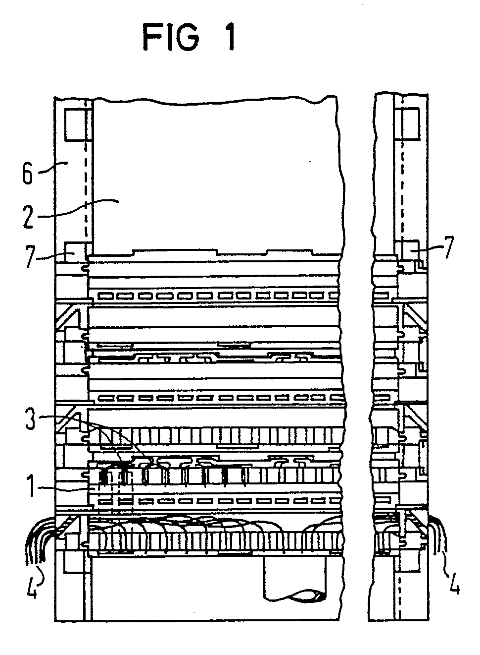
Description
Die Erfindung bezieht sich auf eine Einrichtung zum Anschließen und Verbinden von ankommenden und abgehenden elektrischen Leitungen insbesondere in Verteilern von Fernsprechanlagen. Eine derartige Einrichtung ist z. B. durch die DE-OS 27 25 551 bekannt geworden. Danach sind die elektrischen Leitungen an länglichen Anschlußleisten angeschlossen, die an ihren Enden mittels Schrauben an einem Aufnahmegestell befestigt sind.The invention relates to a device for connecting and connecting incoming and outgoing electrical lines, in particular in distributors of telephone systems. Such a device is e.g. B. become known from DE-OS 27 25 551. The electrical lines are then connected to elongated terminal strips which are fastened at their ends by means of screws to a receiving frame.
Der Erfindung liegt die Aufgabe zugrunde, das Befestigen der Anschlußleisten zu vereinfachen.The invention has for its object to simplify the attachment of the terminal strips.
Diese Aufgabe wird durch die Erfindung gemäß Anspruch 1 gelöst. Die Anschlußleisten können nun in einfacher Weise zunächst an einem Ende auf einen Seitenschenkel so aufgesetzt werden, daß die Befestigungselemente in die Ausnehmungen hineinragen. Daraufhin wird die Anschlußleiste bis zum Verrasten des anderen Endes gegen den zweiten Seitenschenkel geschwenkt. Durch die formschlüssige Verbindung wird das Trägerteil so stabilisiert, daß es sehr dünn gehalten werden kann. Dadurch ist es möglich, das Trägerteil aus dünnem Blech kostengünstig zu biegen. Ein derartiges Blech kann an Erde gelegt werden. Dadurch ist es möglich, Erdungsbleche für Schutzstecker der Anschlußleisten über das Trägerteil einfacher zu erden.This object is achieved by the invention according to claim 1. The terminal strips can now be placed in a simple manner at one end on a side leg so that the fasteners protrude into the recesses. Thereupon, the terminal strip is pivoted against the second side leg until the other end engages. The positive connection stabilizes the carrier part so that it can be kept very thin. This makes it possible to inexpensively bend the carrier part made of thin sheet metal. Such a sheet can be laid on earth. This makes it easier to ground earthing plates for protective plugs of the connection strips via the carrier part.
Durch eine Weiterbildung der Erfindung nach Anspruch 2 wird zwischen benachbarten Trägerteilen unterhalb der Seitenstege ein Verdrahtungsraum für an die Anschlußleiste anzuschließende Rangierdrähte gebildet. Es ergibt sich gleichzeitig eine breite Auflagefläche für die Anschlußleisten.Through a development of the invention according to
Durch die Weiterbildung nach Anspruch 3 erstreckt sich die Ausnehmung im wesentlichen parallel zur Anschlußleiste. Die Ausnehmungen sind für die Montageperson gut sichtbar, so daß die Befestigungselemente leichter eingefädelt werden können. Die hakenartigen Befestigungselemente hintergreifen mit entsprechenden Vorsprüngen den Seitensteg auf einer Länge, die größer sein kann als das Blech dick ist. Auf diese Weise wird eine sichere Verriegelung erreicht. Die Rastelemente auf der anderen Seite überragen den Seitensteg und sind dadurch gut zugänglich. Sie können von außen her leicht entriegelt werden.Due to the development according to
Im folgenden wird die Erfindung anhand eines in der Zeichnung dargestellten Ausführungsbeispiels näher erläutert.The invention is explained in more detail below on the basis of an exemplary embodiment shown in the drawing.
Die Figuren 1, 2 und 3 zeigen in drei verschiedenen Ansichten einen Verteilerblock, der aus längsseitig aneinander gereihten Anschlußleisten 1 und einem Trägerteil 2 für die Anschlußleisten 1 besteht. An die Anschlußleisten sind ankommende elektrische Leitungen 3 und abgehende Leitungen 4 angeschlossen. Das Trägerteil 2 ist aus Blech u-förmig gebogen. Die Anschlußleisten 1 sind von länglicher Gestalt und quer zur Längsrichtung des Trägerteils 2 an dessen Seitenschenkeln 5 befestigt. Deren freie Enden sind rechtwinklig nach außen zu einem Seitensteg abgebogen. Im Bereich dieser Biegung sind in dem Seitenschenkel 5 mit dem Seitensteg 6 Ausnehmungen 7 vorgesehen, in die Rastelemente 8 und Befestigungselemente 9 der Anschlußleiste 1 eingreifen. Die Rastelemente 8 und Befestigungselemente 9 sind einstückig mit einem Isolierstoffkörper der Anschlußleiste 1 verbunden. Die Befestigungselemente 9 sind hakenartig ausgebildet und können durch Schwenken der Anschlußleiste 1 in die entsprechenden Ausnehmungen 6 derart eingesetzt werden, daß zwischen dem entsprechenden Seitenschenkel 5 und der Anschlußleiste 1 ein Formschluß entsteht. Die Rastelemente 8 am anderen Ende der Anschlußleisten 1 ragen in die Richtung der Seitenschenkel 5. Sie weisen eine gefederte Rastnase 10 auf, die den Seitensteg von innen her hintergreift. Auf der Seite der Rasthaken 8 weist die Anschlußleiste 1 Vorsprünge 11 auf, die den Seitenschenkel 5 an der Ausnehmung 7 gabelförmig umgreifen und damit formschlüssig fixieren. Dies wird dadurch ermöglicht, daß die Ausnehmung 7 sich zu beiden Seiten der Biegung für den Seitensteg 6 erstreckt.Figures 1, 2 and 3 show in three different views a distributor block, which consists of side-by-side connection strips 1 and a
Claims (3)
dadurch gekennzeichnet,
daß das Trägerteil (2) aus dünnem Material kanalartig ausgebildet ist,
daß der Abstand von Seitenschenkeln (5) des Trägerteils (2) ungefähr gleich der Länge der Anschlußleisten ist, daß diese auf die Enden der Seitenschenkel (5) des Trägerteils (2) aufgesetzt sind,
daß die Seitenschenkel (5) Ausnehmungen (7) zum Befestigen der Anschlußleisten (1) aufweisen,
daß Isolierstoffkörper der Anschlußleisten einstückig Befestigungselemente (9) und Rastelemente (8) aufweisen, die in die Ausnehmungen (7) eingreifen und
daß die Seitenschenkel (5) und die Anschlußleisten (1) formschlüssig miteinander verbunden sind.1. Device for connecting and connecting incoming and outgoing electrical lines (3, 4) in particular in distributors of telephone systems, the device having terminal strips (1) with connecting elements for the incoming and outgoing lines and the terminal strips (1) on a carrier part (2) the device is attached,
characterized,
that the carrier part (2) is made of thin material like a channel,
that the distance from the side legs (5) of the carrier part (2) is approximately equal to the length of the connection strips, that these are placed on the ends of the side legs (5) of the carrier part (2),
that the side legs (5) have recesses (7) for fastening the terminal strips (1),
that insulating body of the terminal strips have one-piece fastening elements (9) and locking elements (8) which engage in the recesses (7) and
that the side legs (5) and the terminal strips (1) are positively connected.
dadurch gekennzeichnet,
daß die freien Enden der Seitenschenkel (5) als Seitenstege (6) ausgebildet sind, die nach außen hin parallel zur Basis des Trägerteils (2) abgewinkelt sind.2. Device according to claim 1,
characterized,
that the free ends of the side legs (5) are designed as side webs (6) which are angled outwards parallel to the base of the carrier part (2).
dadurch gekennzeichnet,
daß die Ausnehmungen (7) zumindest abschnittsweise im Bereich des Seitenstegs (6) liegen,
daß die Befestigungselemente (9) an einem Ende der Anschlußleiste (1) hakenartig ausgebildet sind und den zugehörigen Seitensteg (6) hintergreifen und
daß die Rastelemente (8) am anderen Ende der Anschlußleiste (1) als Rasthaken ausgebildet sind, die mit einer gefederten Rastnase (10) den Seitensteg (6) von innen her hintergreifen.3. Device according to claim 2,
characterized,
that the recesses (7) lie at least in sections in the region of the side web (6),
that the fasteners (9) are hook-like at one end of the terminal block (1) and engage behind the associated side web (6) and
that the locking elements (8) at the other end of the terminal block (1) are designed as locking hooks which engage behind the side web (6) from the inside with a spring-loaded locking lug (10).
Applications Claiming Priority (2)
| Application Number | Priority Date | Filing Date | Title |
|---|---|---|---|
| DE8716918U DE8716918U1 (en) | 1987-12-23 | 1987-12-23 | Device for connecting and connecting electrical cables |
| DE8716918U | 1987-12-23 |
Publications (3)
| Publication Number | Publication Date |
|---|---|
| EP0321752A2 true EP0321752A2 (en) | 1989-06-28 |
| EP0321752A3 EP0321752A3 (en) | 1990-05-23 |
| EP0321752B1 EP0321752B1 (en) | 1994-10-19 |
Family
ID=6815434
Family Applications (1)
| Application Number | Title | Priority Date | Filing Date |
|---|---|---|---|
| EP88120008A Expired - Lifetime EP0321752B1 (en) | 1987-12-23 | 1988-11-30 | Device to connect and join electrical conductors together |
Country Status (6)
| Country | Link |
|---|---|
| EP (1) | EP0321752B1 (en) |
| AT (1) | ATE113142T1 (en) |
| AU (1) | AU613131B2 (en) |
| DE (2) | DE8716918U1 (en) |
| FI (1) | FI885947A7 (en) |
| NO (1) | NO175446C (en) |
Cited By (1)
| Publication number | Priority date | Publication date | Assignee | Title |
|---|---|---|---|---|
| RU2127014C1 (en) * | 1993-05-05 | 1999-02-27 | Кроне Аг | Distribution cabinet |
Families Citing this family (1)
| Publication number | Priority date | Publication date | Assignee | Title |
|---|---|---|---|---|
| DE3921224A1 (en) * | 1989-06-28 | 1991-01-10 | Siemens Ag | Elongated connection moulding for telecommunication distributor - contains channels with progressively increased spacing for outgoing wires from operational face to corresp. connection elements |
Family Cites Families (6)
| Publication number | Priority date | Publication date | Assignee | Title |
|---|---|---|---|---|
| DE1196245B (en) * | 1962-03-28 | 1965-07-08 | Siemens Ag | Line-up distributor |
| DE2309579C2 (en) * | 1973-02-26 | 1984-01-12 | Siemens AG, 1000 Berlin und 8000 München | Component for setting up distribution boards |
| US3899237A (en) * | 1973-09-10 | 1975-08-12 | Bell Telephone Labor Inc | Connecting block structures for modular main distribution frames |
| DE2725551C2 (en) * | 1977-06-07 | 1983-11-17 | Krone Gmbh, 1000 Berlin | Electrical clamp connector |
| DE3509523C3 (en) * | 1985-03-16 | 1996-07-04 | Quante Ag | Cable termination unit |
| DE8716919U1 (en) * | 1987-12-23 | 1988-02-18 | Siemens AG, 1000 Berlin und 8000 München | Connection block for incoming and outgoing electrical cables |
-
1987
- 1987-12-23 DE DE8716918U patent/DE8716918U1/en not_active Expired
-
1988
- 1988-11-30 AT AT88120008T patent/ATE113142T1/en not_active IP Right Cessation
- 1988-11-30 EP EP88120008A patent/EP0321752B1/en not_active Expired - Lifetime
- 1988-11-30 DE DE3851873T patent/DE3851873D1/en not_active Expired - Fee Related
- 1988-12-22 AU AU27524/88A patent/AU613131B2/en not_active Ceased
- 1988-12-22 FI FI885947A patent/FI885947A7/en not_active IP Right Cessation
- 1988-12-23 NO NO885736A patent/NO175446C/en unknown
Cited By (1)
| Publication number | Priority date | Publication date | Assignee | Title |
|---|---|---|---|---|
| RU2127014C1 (en) * | 1993-05-05 | 1999-02-27 | Кроне Аг | Distribution cabinet |
Also Published As
| Publication number | Publication date |
|---|---|
| NO885736D0 (en) | 1988-12-23 |
| ATE113142T1 (en) | 1994-11-15 |
| AU613131B2 (en) | 1991-07-25 |
| DE8716918U1 (en) | 1988-02-18 |
| FI885947L (en) | 1989-06-24 |
| EP0321752A3 (en) | 1990-05-23 |
| NO175446B (en) | 1994-07-04 |
| FI885947A7 (en) | 1989-06-24 |
| AU2752488A (en) | 1989-06-29 |
| EP0321752B1 (en) | 1994-10-19 |
| DE3851873D1 (en) | 1994-11-24 |
| NO175446C (en) | 1994-10-12 |
| NO885736L (en) | 1989-06-26 |
Similar Documents
| Publication | Publication Date | Title |
|---|---|---|
| DE2725551A1 (en) | DEVICE AND METHOD FOR ESTABLISHING A SOLDER, SCREW- AND STRIPPING-FREE CONTACT TO A FIXED CONNECTOR, IN PARTICULAR FOR THE REMOTE INDICATION TECHNOLOGY | |
| DE3909263A1 (en) | ELECTRICAL CONNECTING DEVICE | |
| DE102016107565A1 (en) | Arrangement for the contact-safe contacting of a busbar system | |
| DE10324144A1 (en) | Electric modular terminal block esp. for positioning on mounting rail, has at least one power line arranged in housing and electrically connected to conductor connection elements | |
| EP2242327A1 (en) | Electric heating device | |
| DE3902124C2 (en) | ||
| DE3422607C2 (en) | ||
| DE20003081U1 (en) | Cable holder | |
| DE3634462C2 (en) | ||
| DE2251020A1 (en) | CONNECTING DEVICE | |
| DE69306223T2 (en) | Adapter for connecting a box-shaped multiphase switch to parallel busbars | |
| DE3428054C2 (en) | ||
| EP0321752A2 (en) | Device to connect and join electrical conductors together | |
| DE8629688U1 (en) | Connection terminal for mounting on busbars | |
| WO2003067725A1 (en) | Connecting or distributing device for electrical installation equipment | |
| DE2712723A1 (en) | ELECTRIC DISTRIBUTOR | |
| EP2544012A1 (en) | Connecting device for an electricity meter | |
| EP1182735A2 (en) | Electrical terminal block | |
| WO1995029520A1 (en) | Busbar and cross connection for a series terminal | |
| DE69711567T2 (en) | Connection device for electrical cables with one or a plurality of conductors | |
| DE102010053136A1 (en) | Meter support housing for a meter cabinet | |
| EP1251537B1 (en) | Load break switch of the strip type with fuses | |
| DE9308325U1 (en) | Connectors with means for snapping onto mounting rails | |
| DE10350465A1 (en) | Widening element for assembly strap for securing and wiring for electric units, especially in switchgear cubicles, with first integrally formed holder with U-shaped profile for strip-shaped strap edge section | |
| DE2812089C2 (en) | Screw and solderable fastening device for electrical conductors |
Legal Events
| Date | Code | Title | Description |
|---|---|---|---|
| PUAI | Public reference made under article 153(3) epc to a published international application that has entered the european phase |
Free format text: ORIGINAL CODE: 0009012 |
|
| AK | Designated contracting states |
Kind code of ref document: A2 Designated state(s): AT BE CH DE FR GB LI NL |
|
| PUAL | Search report despatched |
Free format text: ORIGINAL CODE: 0009013 |
|
| AK | Designated contracting states |
Kind code of ref document: A3 Designated state(s): AT BE CH DE FR GB LI NL |
|
| 17P | Request for examination filed |
Effective date: 19900807 |
|
| 17Q | First examination report despatched |
Effective date: 19921223 |
|
| GRAA | (expected) grant |
Free format text: ORIGINAL CODE: 0009210 |
|
| AK | Designated contracting states |
Kind code of ref document: B1 Designated state(s): AT BE CH DE FR GB LI NL |
|
| REF | Corresponds to: |
Ref document number: 113142 Country of ref document: AT Date of ref document: 19941115 Kind code of ref document: T |
|
| REF | Corresponds to: |
Ref document number: 3851873 Country of ref document: DE Date of ref document: 19941124 |
|
| GBT | Gb: translation of ep patent filed (gb section 77(6)(a)/1977) |
Effective date: 19950106 |
|
| ET | Fr: translation filed | ||
| PLBE | No opposition filed within time limit |
Free format text: ORIGINAL CODE: 0009261 |
|
| STAA | Information on the status of an ep patent application or granted ep patent |
Free format text: STATUS: NO OPPOSITION FILED WITHIN TIME LIMIT |
|
| 26N | No opposition filed | ||
| PGFP | Annual fee paid to national office [announced via postgrant information from national office to epo] |
Ref country code: GB Payment date: 19951019 Year of fee payment: 8 |
|
| PGFP | Annual fee paid to national office [announced via postgrant information from national office to epo] |
Ref country code: AT Payment date: 19951025 Year of fee payment: 8 |
|
| PGFP | Annual fee paid to national office [announced via postgrant information from national office to epo] |
Ref country code: BE Payment date: 19951116 Year of fee payment: 8 |
|
| PGFP | Annual fee paid to national office [announced via postgrant information from national office to epo] |
Ref country code: NL Payment date: 19951117 Year of fee payment: 8 |
|
| PGFP | Annual fee paid to national office [announced via postgrant information from national office to epo] |
Ref country code: FR Payment date: 19951123 Year of fee payment: 8 |
|
| PGFP | Annual fee paid to national office [announced via postgrant information from national office to epo] |
Ref country code: CH Payment date: 19960216 Year of fee payment: 8 |
|
| PG25 | Lapsed in a contracting state [announced via postgrant information from national office to epo] |
Ref country code: LI Effective date: 19961130 Ref country code: GB Effective date: 19961130 Ref country code: CH Effective date: 19961130 Ref country code: BE Effective date: 19961130 Ref country code: AT Effective date: 19961130 |
|
| BERE | Be: lapsed |
Owner name: SIEMENS A.G. Effective date: 19961130 |
|
| PG25 | Lapsed in a contracting state [announced via postgrant information from national office to epo] |
Ref country code: NL Effective date: 19970601 |
|
| REG | Reference to a national code |
Ref country code: CH Ref legal event code: PL |
|
| GBPC | Gb: european patent ceased through non-payment of renewal fee |
Effective date: 19961130 |
|
| PG25 | Lapsed in a contracting state [announced via postgrant information from national office to epo] |
Ref country code: FR Effective date: 19970731 |
|
| NLV4 | Nl: lapsed or anulled due to non-payment of the annual fee |
Effective date: 19970601 |
|
| REG | Reference to a national code |
Ref country code: FR Ref legal event code: ST |
|
| PGFP | Annual fee paid to national office [announced via postgrant information from national office to epo] |
Ref country code: DE Payment date: 19990120 Year of fee payment: 11 |
|
| PG25 | Lapsed in a contracting state [announced via postgrant information from national office to epo] |
Ref country code: DE Free format text: LAPSE BECAUSE OF NON-PAYMENT OF DUE FEES Effective date: 20000901 |