EP0321780A2 - Hand lever for a single-lever mixing valve - Google Patents
Hand lever for a single-lever mixing valve Download PDFInfo
- Publication number
- EP0321780A2 EP0321780A2 EP88120412A EP88120412A EP0321780A2 EP 0321780 A2 EP0321780 A2 EP 0321780A2 EP 88120412 A EP88120412 A EP 88120412A EP 88120412 A EP88120412 A EP 88120412A EP 0321780 A2 EP0321780 A2 EP 0321780A2
- Authority
- EP
- European Patent Office
- Prior art keywords
- lever
- hand lever
- head housing
- housing
- jacket
- Prior art date
- Legal status (The legal status is an assumption and is not a legal conclusion. Google has not performed a legal analysis and makes no representation as to the accuracy of the status listed.)
- Granted
Links
Images

Classifications
-
- F—MECHANICAL ENGINEERING; LIGHTING; HEATING; WEAPONS; BLASTING
- F16—ENGINEERING ELEMENTS AND UNITS; GENERAL MEASURES FOR PRODUCING AND MAINTAINING EFFECTIVE FUNCTIONING OF MACHINES OR INSTALLATIONS; THERMAL INSULATION IN GENERAL
- F16K—VALVES; TAPS; COCKS; ACTUATING-FLOATS; DEVICES FOR VENTING OR AERATING
- F16K31/00—Actuating devices; Operating means; Releasing devices
- F16K31/44—Mechanical actuating means
- F16K31/60—Handles
- F16K31/605—Handles for single handle mixing valves
Definitions
- the invention relates to a hand lever actuation device for one-handle mixer valves according to the preamble of claim 1.
- a hand lever is designed as a bracket, two parallel ring arches of the lever arm sliding tangentially through correspondingly shaped openings in the jacket sleeve of the lever head and brought together in the outer region to form a handle.
- the two lever arms are each provided in the area through the wall of the lever head housing with an arc around the center of the pivot axis of the inner lever, so that these arcs are in the user's field of vision.
- the invention has for its object to provide a different design of the lever handle shaped as a bow handle and the lever head housing, while keeping the slimest possible shape of the lever head housing.
- the engagement mixer valve shown in particular in Figures 1 to 4 consists essentially of a valve housing 4 with connections for cold and hot water, not shown in the drawing, a cartridge housing 5, in which ceramic valve disks are arranged as valve members and in which an inner lever 11 around a Swivel bearing axis 51 pivotable and by one rotation axis 12 is rotatably arranged.
- the hand lever actuating device 1 is formed above the valve housing 4 in a partial area of the cartridge housing 5.
- the hand lever actuation device 1 consists of a lever head housing 2 and a hand lever 3.
- the lever head housing is formed in two parts and consists of a jacket part 21 and a hood 22, while the hand lever 3 is formed in one piece and is positively connected to the inner lever 11, a screw 13 accessible from above being provided for securing.
- the jacket part 21 of the lever head housing 2 essentially consists of a cylindrical sleeve on which two opposite windows 211 are formed from the upper end face, the bottom of which each forms one half of a passage opening 23 .
- Corresponding adapters 221 are integrally formed on the hood 22, as is shown in particular in FIGS. 5 and 6 of the drawing.
- the fitting pieces 221 can be pushed into the windows 211, the end faces of the fitting pieces 221 being designed and shaped such that they form the second half of the passage openings 23.
- the hood 22 forms the front cover of the jacket part 21 and closes the windows 211 except for the passage openings 23.
- snap tongues 27 are formed on the hood 22 with which the hood 22 can be locked on the jacket part 21.
- the hand lever 3 as is shown in particular in FIGS. 9 and 10, is produced in one piece using the zinc die-casting method, the arms of the bracket part, which are guided in parallel, being brought tangentially to the cylindrical part of the lever head housing 2.
- a crosspiece 34 is formed, in which the inner lever 11 is received in a form-fitting manner.
- cheeks 32 are formed on both sides, on each of which a pin 31 having a circular cross section is formed perpendicular to the axis of rotation 12 and establish the connection to the bow-shaped part of the hand lever 3.
- the hand lever 3 is pulled down with its cheeks 32 into the vicinity of the fastening screws 52 of the cartridge housing 5 in order to achieve the shortest possible swivel arc for swiveling the hand lever 3 around the swivel bearing axis 51.
- the passage openings 23 therefore have the shape of an annular arc piece 24, as can be seen in particular from FIG. 4.
- the center of the ring arc is formed by the pivot bearing axis 51.
- the cartridge housing 5 is fastened to the valve housing 4 with the valve members and the inner lever 11 with the fastening screws 52.
- the jacket part 21 can then be slipped over the cartridge housing 5 and supported with its end face on the valve housing 4.
- the hand lever 3 is pushed with its transverse web 34 onto the protruding inner lever arm 11, which is approximately square in cross section, and secured with the screw 13.
- the hand lever 3 with its pin 31 in the bottom of the Window 211 superimposed.
- the hood with its fitting pieces 221 can be inserted into the windows 211 and locked in the plug-in position with the snap tongues 27, so that the two pins 31 are now each mounted in an arcuate passage opening 23.
- the annular arc 24 is dimensioned so that the hand lever 3 can be brought from its closed position, as shown in Figure 4, by lifting or pivoting about the pivot bearing axis 51 in a position in which the full flow through the mixing valve is released becomes. If, on the other hand, the mixing ratio is to be changed, the hand lever 3 is pivoted about the axis of rotation 12.
- parallel contact surfaces 25 are provided which each has a cheek 32 of the transverse web 34 with an approximately circular end face and thus a positive entrainment of the lever head housing 2 is ensured during the pivoting movement about the axis of rotation 12.
- approximately circular flats 26 are formed on the outside in the area of the passage openings 23, the hand lever 3 being in the area of the introduction into the Lever head housing 2 has appropriately shaped widenings 33.
Landscapes
- Engineering & Computer Science (AREA)
- General Engineering & Computer Science (AREA)
- Mechanical Engineering (AREA)
- Multiple-Way Valves (AREA)
- Sheet Holders (AREA)
- Mechanically-Actuated Valves (AREA)
Abstract
Bei einer Handhebelbetätigungseinrichtung für Eingriffmischventile mit einem in einer Kartusche angeordneten, in zwei Freiheitsgraden bewegbaren Ventilglied zur separaten Bestimmung des Mischungsverhältnisses und der Gesamtdurchflußmenge, wobei ein mit dem Ventilglied gekoppelter, im Kartuschengehäuse (5) gelagerter innerer Hebel (11) vorgesehen ist, der mit einem um zwei senkrecht zueinander im Ventilgehäuse angeordnete Drehachsen verschwenkbaren, als Bügel ausgebildeten Handhebel (3) fest verbunden und durch den Mantel (21) eines um die erste Drehachse auf dem Ventilgehäuse gehalterten Hebelkopfgehäuse (2) herausgeführt ist, wird vorgeschlagen, daß der Handhebel oberhalb der Schwenklagerachse (51) des inneren Hebels (11) diametral zu beiden Seiten durch den Mantel des Hebelkopfgehäuses (2) herausgeführt ist, wobei die Durchtrittsöffnungen jeweils als Ringbogenstück (24) zur Schwenklagerachse (51) ausgebildet sind. 
Description
Die Erfindung bezieht sich auf eine Handhebelbetätigungsvorrichtung für Eingriffmischventile nach dem Oberbegriff des Anspruchs 1.
Bei einem bekannten Eingriffmischventil dieser Art (DE-OS 33 37 968) ist ein Handhebel als Bügel ausgebildet, wobei zwei parallel angeordnete Ringbögen des Hebelarms tangential durch entsprechend geformte Öffnungen der Mantelhülse des Hebelkopfes hindurchgleiten und im äußeren Bereich zu einem Griffstück zusammengeführt sind. Hierbei kann es als nachteilig angesehen werden, daß die beiden Hebelarme im Bereich der Durchführung durch die Wandung des Hebelkopfgehäuses jeweils mit einem Bogen um den Mittelpunkt der Schwenkachse des inneren Hebels versehen sind, so daß diese Bögen im Blickfeld des Benutzers liegen.The invention relates to a hand lever actuation device for one-handle mixer valves according to the preamble of
In a known one-way mixing valve of this type (DE-OS 33 37 968) a hand lever is designed as a bracket, two parallel ring arches of the lever arm sliding tangentially through correspondingly shaped openings in the jacket sleeve of the lever head and brought together in the outer region to form a handle. Here, it can be considered a disadvantage that the two lever arms are each provided in the area through the wall of the lever head housing with an arc around the center of the pivot axis of the inner lever, so that these arcs are in the user's field of vision.
Der Erfindung liegt die Aufgabe zugrunde, eine andere Ausbildung des als Bügelgriff geformten Handhebels und des Hebelkopfgehäuses zu schaffen, wobei eine möglichst schlanke Gestalt des Hebelkopfgehäuses beibehalten werden soll.The invention has for its object to provide a different design of the lever handle shaped as a bow handle and the lever head housing, while keeping the slimest possible shape of the lever head housing.
Diese Aufgabe wird erfindungsgemäß durch die kennzeichnenden Merkmale des Anspruchs 1 gelöst.
Weitere Ausgestaltungen der Erfindung sind in den Ansprüchen 2 bis 6 angegeben.This object is achieved according to the invention by the characterizing features of
Further refinements of the invention are specified in
Aus der DE-PS 28 56 300 ist es ferner bekannt, beide Arme des das Kopfteil umfassenden Handhebels mit einer auf einer Drehachse im Kopfteil gelagerten Welle, die tangential aus dem Hebelkopfgehäuse herausgeführt ist, zu verbinden. Eine Übertragung dieser bekannten Einrichtung auf ein Eingriffmischventil nach dem Oberbegriff des Patentanspruchs 1, mit einem im Kartuschengehäuse schwenkbar gelagerten inneren Hebel, läßt sich aber bei unveränderter Kartuschenausbildung nicht realisieren bzw. führt zu einer nicht unerheblichen Vergrößerung des Durchmessers des Hebelkopfgehäuses, was aber einer ansprechenden Optik des Mischventils entgegenwirkt. Die mit der Erfindung erzielten Vorteile bestehen im wesentlichen darin, daß bei einer harmonischen Anlenkung des Bügelgriffs an das Hebelkopfgehäuse, dieses relativ schlank ausgebildet werden kann, wobei an der in das Eingriffmischventil eingesetzten Ventilkartusche keinerlei Änderungen vorgenommen werden müssen. Darüber hinaus wird durch eine entsprechende flächige Ausbildung im Bereich der Durchtrittsöffnungen sichergestellt, daß die Durchtrittsöffnung in jeder Schwenkstellung vom Handhebel abgedeckt ist, so daß ein Eindringen von Schmutzwasser etc. in den Hebelkopf verhindert bzw. behindert wird.From DE-PS 28 56 300 it is also known to connect both arms of the hand lever comprising the head part with a shaft mounted on an axis of rotation in the head part, which is guided tangentially out of the lever head housing. A transfer of this known device to a single-action mixer valve according to the preamble of
Ein Ausführungsbeispiel der Erfindung ist in der Zeichnung dargestellt und wird im folgenden näher beschrieben. Es zeigt
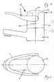
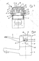
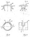
Figur 1 ein Eingriffmischventil mit bügelförmigem Handgriff in Seitenansicht;Figur 2 das Eingriffmischventil gemäßFigur 1 in Draufsicht;Figur 3 das Mischventil gemäßFigur 1 in Vorderansicht, teilweise im Schnitt;Figur 4 das Eingriffmischventil gemäßFigur 1 in Seitenansicht, teilweise im Schnitt;Figur 5 eine Haube des Hebelkopfgehäuses nachFigur 1 in Seitenansicht;- Figur 6 die Haube gemäß
Figur 5 um 90° gedreht; - Figur 7 ein Mantelteil des Hebelkopfgehäuses gemäß
Figur 1 in Draufsicht; - Figur 8 das Mantelteil gemäß Figur 7 in Seitenansicht;
- Figur 9 den Handhebel nach
Figur 1 in Seitenansicht; - Figur 10 den Handhebel gemäß Figur 9 in Draufsicht.
- Figure 1 shows a one-handle mixer valve with a bow-shaped handle in side view;
- Figure 2 shows the single-action mixer valve according to Figure 1 in plan view;
- Figure 3 shows the mixing valve of Figure 1 in front view, partially in section;
- Figure 4 shows the one-handle mixer valve according to Figure 1 in side view, partially in section;
- Figure 5 is a hood of the lever head housing of Figure 1 in side view;
- Figure 6 rotated the hood according to Figure 5 by 90 °;
- Figure 7 shows a jacket part of the lever head housing according to Figure 1 in plan view;
- Figure 8 shows the jacket part of Figure 7 in side view;
- Figure 9 shows the hand lever of Figure 1 in side view;
- Figure 10 shows the hand lever according to Figure 9 in plan view.
Das insbesondere in den Figuren 1 bis 4 gezeigte Eingriffmischventil besteht im wesentlichen aus einem Ventilgehäuse 4 mit in der Zeichnung nicht gezeigten Anschlüssen für Kalt- und Warmwasser, einem Kartuschengehäuse 5, in dem Keramikventilscheiben als Ventilglieder angeordnet sind und in der ein innerer Hebel 11 um eine Schwenklagerachse 51 verschwenkbar und um eine Dreh achse 12 verdrehbar angeordnet ist. Durch ein Verschwenken um die Schwenklagerachse 51 wird dabei die Gesamtdurchflußmenge, durch ein Drehen um die Drehachse 12 das Mischungsverhältnis von Kalt- und Warmwasser mit dem in der Kartusche gekapselt angeordneten Mischventil eingestellt.
Oberhalb des Ventilgehäuses 4 ist in einem Teilbereich des Kartuschengehäuses 5 die Handhebelbetätigungseinrichtung 1 ausgebildet. Die Handhebelbetätigungseinrichtung 1 besteht dabei aus einem Hebelkopfgehäuse 2 und einem Handhebel 3.
Das Hebelkopfgehäuse ist zweiteilig ausgebildet und besteht aus einem Mantelteil 21 und einer Haube 22, während der Handhebel 3 einstückig ausgebildet ist und formschlüssig mit dem inneren Hebel 11 verbunden ist, wobei zur Sicherung eine von oben zugängliche Schraube 13 vorgesehen ist.The engagement mixer valve shown in particular in Figures 1 to 4 consists essentially of a
The hand
The lever head housing is formed in two parts and consists of a
Der Mantelteil 21 des Hebelkopfgehäuses 2, wie er insbesondere in den Figuren 7 und 8 dargestellt ist, besteht im wesentlichen aus einer zylindrischen Hülse, an der von der oberen Stirnseite aus zwei gegenüberliegende Fenster 211 ausgebildet sind, deren Grund jeweils eine Hälfte einer Durchtrittsöffnung 23 bildet. An der Haube 22 sind entsprechende Paßstücke 221 angeformt, wie es insbesondere in Figur 5 und 6 der Zeichnung dargestellt ist. Die Paßstücke 221 sind dabei in die Fenster 211 einschiebbar, wobei die Stirnseiten der Paßstücke 221 so ausgebildet und geformt sind, daß sie die zweite Hälfte der Durchtrittsöffnungen 23 bilden. In der Stecklage bildet die Haube 22 die stirnseitige Abdeckung des Mantelteils 21 und verschließt die Fenster 211 bis auf die Durchtrittsöffnungen 23. Zur Sicherung in der Stecklage sind an der Haube 22 Schnappzungen 27 ausgebildet, mit der die Haube 22 an dem Mantelteil 21 verrastbar ist.The
Der Handhebel 3, wie er insbesondere in den Figuren 9 und 10 dargestellt ist, ist einstückig im Zinkdruckgußverfahren hergestellt, wobei die parallel geführten Arme des Bügelteils tangential an dem zylindrischen Teil des Hebelkopfgehäuses 2 herangeführt ist. Zwischen dem gabelförmigen Bügelteil ist ein Quersteg 34 ausgebildet, in dem zentral der innere Hebel 11 formschlüssig aufgenommen ist. Verkröpft zu dem Quersteg 34 sind an beiden Seiten Wangen 32 ausgebildet, an denen jeweils ein im Querschnitt Kreisform aufweisender Zapfen 31 senkrecht zur Drehachse 12 angeformt ist und die Verbindung zum bügelförmigen Teil des Handhebels 3 herstellen. Der Handhebel 3 ist dabei mit seinen Wangen 32 bis in die Nähe der Befestigungsschrauben 52 des Kartuschengehäuses 5 heruntergezogen, um einen möglichst kurzen Schwenkbogen zum Verschwenken des Handhebels 3 um die Schwenklagerachse 51 zu erreichen. Die Durchtrittsöffnungen 23 weisen daher die Form eines Ringbogenstücks 24 auf, wie es insbesondere aus Figur 4 ersichtlich ist. Das Zentrum des Ringbogens wird dabei von der Schwenklagerachse 51 gebildet.The
Die Montage und die Funktion der vorstehend beschriebenen Handhebelbetätigungseinrichtung erfolgt in folgender Weise:
Zunächst wird das Kartuschengehäuse 5 mit den Ventilgliedern und dem inneren Hebel 11 mit den Befestigungsschrauben 52 am Ventilgehäuse 4 befestigt. Danach kann der Mantelteil 21 über das Kartuschengehäuse 5 gestreift und mit seiner Stirnfläche am Ventilgehäuse 4 aufgelagert werden. Nunmehr wird der Handhebel 3 mit seinem Quersteg 34 auf den im Querschnitt etwa quadratisch ausgebildeten, vorstehenden inneren Hebelarm 11 aufgeschoben und mit der Schraube 13 gesichert. Hierbei ist der Handhebel 3 mit seinen Zapfen 31 im Grund der Fenster 211 aufgelagert. Nunmehr kann die Haube mit ihren Paßstücken 221 in die Fenster 211 eingeführt und in der Stecklage mit den Schnappzungen 27 verrastet werden, so daß nunmehr die beiden Zapfen 31 jeweils in einer ringbogenförmigen Durchtrittsöffnung 23 gelagert sind. Der Ringbogen 24 ist dabei so dimensioniert, daß der Handhebel 3 von seiner Schließstellung, wie sie in der Figur 4 dargestellt ist, durch Anheben bzw. Verschwenken um die Schwenklagerachse 51 in eine Position gebracht werden kann, in der der volle Durchfluß durch das Mischventil freigegeben wird.
Soll dagegen das Mischungsverhältnis geändert werden, so erfolgt ein Verschwenken des Handhebels 3 um die Drehachse 12. Hierzu sind, wie es insbesondere aus Figur 7 zu entnehmen ist, im Bereich der Durchtrittsöffnungen 23 an der Innenseite des Hebelkopfgehäuses 2 parallel ausgebildete Anlageflächen 25 vorgesehen, an denen jeweils eine Wange 32 des Querstegs 34 mit einer etwa kreisförmigen Stirnfläche anliegt und somit eine formschlüssige Mitnahme des Hebelkopfgehäuses 2 bei der Schwenkbewegung um die Drehachse 12 gewährleistet ist.The assembly and function of the hand lever actuation device described above is carried out in the following way:
First, the
If, on the other hand, the mixing ratio is to be changed, the
Zur harmonischen Anlenkung der beiden Arme des bügelförmigen Teils des Handhebels 3 und zur Verhinderung des Eindringens von Spritzwasser in das Innere des Hebelkopfgehäuses 2 sind an der Außenseite im Bereich der Durchtrittsöffnungen 23 etwa kreisförmige Anflächungen 26 angeformt, wobei der Handhebel 3 im Bereich der Einführungen in das Hebelkopfgehäuse 2 entsprechend geformte Verbreiterungen 33 aufweist.For the harmonious articulation of the two arms of the bow-shaped part of the
Claims (6)
Priority Applications (1)
| Application Number | Priority Date | Filing Date | Title |
|---|---|---|---|
| AT88120412T ATE82050T1 (en) | 1987-12-19 | 1988-12-07 | HAND LEVER FOR ONE-WAY MIXING VALVES. |
Applications Claiming Priority (2)
| Application Number | Priority Date | Filing Date | Title |
|---|---|---|---|
| DE3743212 | 1987-12-19 | ||
| DE19873743212 DE3743212A1 (en) | 1987-12-19 | 1987-12-19 | HAND LEVER FOR HANDLE MIXING VALVES |
Publications (3)
| Publication Number | Publication Date |
|---|---|
| EP0321780A2 true EP0321780A2 (en) | 1989-06-28 |
| EP0321780A3 EP0321780A3 (en) | 1990-05-16 |
| EP0321780B1 EP0321780B1 (en) | 1992-11-04 |
Family
ID=6343052
Family Applications (1)
| Application Number | Title | Priority Date | Filing Date |
|---|---|---|---|
| EP88120412A Expired - Lifetime EP0321780B1 (en) | 1987-12-19 | 1988-12-07 | Hand lever for a single-lever mixing valve |
Country Status (3)
| Country | Link |
|---|---|
| EP (1) | EP0321780B1 (en) |
| AT (1) | ATE82050T1 (en) |
| DE (2) | DE3743212A1 (en) |
Cited By (1)
| Publication number | Priority date | Publication date | Assignee | Title |
|---|---|---|---|---|
| EP0499716A1 (en) * | 1991-02-21 | 1992-08-26 | KNEBEL & RÖTTGER GMBH. & CO. | Single handle mixing valve for sanitary installation |
Families Citing this family (1)
| Publication number | Priority date | Publication date | Assignee | Title |
|---|---|---|---|---|
| DE502004004764D1 (en) * | 2004-12-16 | 2007-10-04 | Arwa Ag | Single lever mixing valve with bow handle |
Family Cites Families (3)
| Publication number | Priority date | Publication date | Assignee | Title |
|---|---|---|---|---|
| DE3327776A1 (en) * | 1983-08-02 | 1985-02-14 | Friedrich Grohe Armaturenfabrik Gmbh & Co, 5870 Hemer | Hand lever for single-handle mixer valves |
| DE3503583A1 (en) * | 1984-07-03 | 1986-08-07 | Friedrich Grohe Armaturenfabrik Gmbh & Co, 5870 Hemer | WATER MIXING VALVE |
| DE3426740A1 (en) * | 1984-07-20 | 1986-01-30 | Hansa Metallwerke Ag, 7000 Stuttgart | Single-lever mixer |
-
1987
- 1987-12-19 DE DE19873743212 patent/DE3743212A1/en not_active Withdrawn
-
1988
- 1988-12-07 DE DE8888120412T patent/DE3875709D1/en not_active Expired - Lifetime
- 1988-12-07 EP EP88120412A patent/EP0321780B1/en not_active Expired - Lifetime
- 1988-12-07 AT AT88120412T patent/ATE82050T1/en not_active IP Right Cessation
Cited By (2)
| Publication number | Priority date | Publication date | Assignee | Title |
|---|---|---|---|---|
| EP0499716A1 (en) * | 1991-02-21 | 1992-08-26 | KNEBEL & RÖTTGER GMBH. & CO. | Single handle mixing valve for sanitary installation |
| AU639853B2 (en) * | 1991-02-21 | 1993-08-05 | Knebel & Rottger Gmbh & Co | Single arm mixer for hygenic installations |
Also Published As
| Publication number | Publication date |
|---|---|
| EP0321780B1 (en) | 1992-11-04 |
| DE3875709D1 (en) | 1992-12-10 |
| ATE82050T1 (en) | 1992-11-15 |
| DE3743212A1 (en) | 1989-06-29 |
| EP0321780A3 (en) | 1990-05-16 |
Similar Documents
| Publication | Publication Date | Title |
|---|---|---|
| DE60225868T2 (en) | Actuator for a helmet visor | |
| DE2811398B1 (en) | scissors | |
| EP0140275B1 (en) | Hand lever for a single-lever mixing valve | |
| DE3002754A1 (en) | Arbitrarily operated remote control of a swiveling lock of an opening of a vehicle | |
| DE4009276C2 (en) | Door locking device | |
| DE10105541A1 (en) | Actuator for a hood of a motor vehicle | |
| EP0172329A1 (en) | Mixing valves | |
| DE10317808A1 (en) | Handle for valves | |
| DE3902731A1 (en) | Actuating member for the rotatable spindle of a fitting | |
| EP0321780B1 (en) | Hand lever for a single-lever mixing valve | |
| DE2815129C2 (en) | Rotary drive mechanism for low-voltage circuit breakers with toggle levers | |
| DE3103369C2 (en) | ||
| DE19847039C1 (en) | Gas pipe shutoff valve fitting has a ring section with an inner collar with structured cut-outs and recesses to be operated by the handgrip in a low cost assembly for fitting into the housing without modification | |
| WO1997028020A9 (en) | DEVICE FOR LOCKING A CONTAINER ON A VEHICLE CHASSIS | |
| DE2911586C2 (en) | ||
| DE2856300C3 (en) | Hand lever for a single handle mixer tap | |
| DE1660878C3 (en) | Zigzag sewing machine | |
| DE3807168C2 (en) | Movable connection piece for vacuum cleaner accessories | |
| DE60021640T2 (en) | With handlebar mounted steering column switch for driving direction display friction or button switch or the like | |
| EP0236565A1 (en) | Actuating tool | |
| DE4009277C2 (en) | Door locking device | |
| DE4446741B4 (en) | actuator | |
| DE9420804U1 (en) | Gas stove with switch unit | |
| DE202010008051U1 (en) | Air vents as equipment for motor vehicles | |
| EP0195999B1 (en) | Mixing valve |
Legal Events
| Date | Code | Title | Description |
|---|---|---|---|
| PUAI | Public reference made under article 153(3) epc to a published international application that has entered the european phase |
Free format text: ORIGINAL CODE: 0009012 |
|
| AK | Designated contracting states |
Kind code of ref document: A2 Designated state(s): AT CH DE FR GB IT LI NL SE |
|
| PUAL | Search report despatched |
Free format text: ORIGINAL CODE: 0009013 |
|
| AK | Designated contracting states |
Kind code of ref document: A3 Designated state(s): AT CH DE FR GB IT LI NL SE |
|
| 17P | Request for examination filed |
Effective date: 19900516 |
|
| 17Q | First examination report despatched |
Effective date: 19910627 |
|
| RAP1 | Party data changed (applicant data changed or rights of an application transferred) |
Owner name: FRIEDRICH GROHE AKTIENGESELLSCHAFT |
|
| GRAA | (expected) grant |
Free format text: ORIGINAL CODE: 0009210 |
|
| AK | Designated contracting states |
Kind code of ref document: B1 Designated state(s): AT CH DE FR GB IT LI NL SE |
|
| REF | Corresponds to: |
Ref document number: 82050 Country of ref document: AT Date of ref document: 19921115 Kind code of ref document: T |
|
| REF | Corresponds to: |
Ref document number: 3875709 Country of ref document: DE Date of ref document: 19921210 |
|
| ITF | It: translation for a ep patent filed | ||
| ET | Fr: translation filed | ||
| GBT | Gb: translation of ep patent filed (gb section 77(6)(a)/1977) |
Effective date: 19920205 |
|
| PLBE | No opposition filed within time limit |
Free format text: ORIGINAL CODE: 0009261 |
|
| STAA | Information on the status of an ep patent application or granted ep patent |
Free format text: STATUS: NO OPPOSITION FILED WITHIN TIME LIMIT |
|
| 26N | No opposition filed | ||
| EAL | Se: european patent in force in sweden |
Ref document number: 88120412.7 |
|
| PGFP | Annual fee paid to national office [announced via postgrant information from national office to epo] |
Ref country code: SE Payment date: 19991122 Year of fee payment: 12 |
|
| PGFP | Annual fee paid to national office [announced via postgrant information from national office to epo] |
Ref country code: GB Payment date: 19991201 Year of fee payment: 12 |
|
| PGFP | Annual fee paid to national office [announced via postgrant information from national office to epo] |
Ref country code: CH Payment date: 19991213 Year of fee payment: 12 |
|
| PGFP | Annual fee paid to national office [announced via postgrant information from national office to epo] |
Ref country code: AT Payment date: 19991227 Year of fee payment: 12 |
|
| PGFP | Annual fee paid to national office [announced via postgrant information from national office to epo] |
Ref country code: FR Payment date: 19991230 Year of fee payment: 12 |
|
| PGFP | Annual fee paid to national office [announced via postgrant information from national office to epo] |
Ref country code: NL Payment date: 19991231 Year of fee payment: 12 |
|
| NLT1 | Nl: modifications of names registered in virtue of documents presented to the patent office pursuant to art. 16 a, paragraph 1 |
Owner name: FRIEDRICH GROHE AG & CO. KG |
|
| REG | Reference to a national code |
Ref country code: CH Ref legal event code: PFA Free format text: FRIEDRICH GROHE AKTIENGESELLSCHAFT TRANSFER- FRIEDRICH GROHE AG & CO. KG |
|
| REG | Reference to a national code |
Ref country code: FR Ref legal event code: CJ |
|
| PG25 | Lapsed in a contracting state [announced via postgrant information from national office to epo] |
Ref country code: GB Free format text: LAPSE BECAUSE OF NON-PAYMENT OF DUE FEES Effective date: 20001207 Ref country code: AT Free format text: LAPSE BECAUSE OF NON-PAYMENT OF DUE FEES Effective date: 20001207 |
|
| PG25 | Lapsed in a contracting state [announced via postgrant information from national office to epo] |
Ref country code: SE Free format text: LAPSE BECAUSE OF NON-PAYMENT OF DUE FEES Effective date: 20001208 |
|
| PG25 | Lapsed in a contracting state [announced via postgrant information from national office to epo] |
Ref country code: LI Free format text: LAPSE BECAUSE OF NON-PAYMENT OF DUE FEES Effective date: 20001231 Ref country code: CH Free format text: LAPSE BECAUSE OF NON-PAYMENT OF DUE FEES Effective date: 20001231 |
|
| PG25 | Lapsed in a contracting state [announced via postgrant information from national office to epo] |
Ref country code: NL Free format text: LAPSE BECAUSE OF NON-PAYMENT OF DUE FEES Effective date: 20010701 |
|
| GBPC | Gb: european patent ceased through non-payment of renewal fee |
Effective date: 20001207 |
|
| EUG | Se: european patent has lapsed |
Ref document number: 88120412.7 |
|
| REG | Reference to a national code |
Ref country code: CH Ref legal event code: PL |
|
| PG25 | Lapsed in a contracting state [announced via postgrant information from national office to epo] |
Ref country code: FR Free format text: LAPSE BECAUSE OF NON-PAYMENT OF DUE FEES Effective date: 20010831 |
|
| NLV4 | Nl: lapsed or anulled due to non-payment of the annual fee |
Effective date: 20010701 |
|
| REG | Reference to a national code |
Ref country code: FR Ref legal event code: ST |
|
| PGFP | Annual fee paid to national office [announced via postgrant information from national office to epo] |
Ref country code: DE Payment date: 20021209 Year of fee payment: 15 |
|
| PG25 | Lapsed in a contracting state [announced via postgrant information from national office to epo] |
Ref country code: DE Free format text: LAPSE BECAUSE OF NON-PAYMENT OF DUE FEES Effective date: 20040701 |
|
| PG25 | Lapsed in a contracting state [announced via postgrant information from national office to epo] |
Ref country code: IT Free format text: LAPSE BECAUSE OF NON-PAYMENT OF DUE FEES;WARNING: LAPSES OF ITALIAN PATENTS WITH EFFECTIVE DATE BEFORE 2007 MAY HAVE OCCURRED AT ANY TIME BEFORE 2007. THE CORRECT EFFECTIVE DATE MAY BE DIFFERENT FROM THE ONE RECORDED. Effective date: 20051207 |