EP0321802B1 - Montage d'un caloporteur sous le plafond d'un espace - Google Patents
Montage d'un caloporteur sous le plafond d'un espace Download PDFInfo
- Publication number
- EP0321802B1 EP0321802B1 EP88120610A EP88120610A EP0321802B1 EP 0321802 B1 EP0321802 B1 EP 0321802B1 EP 88120610 A EP88120610 A EP 88120610A EP 88120610 A EP88120610 A EP 88120610A EP 0321802 B1 EP0321802 B1 EP 0321802B1
- Authority
- EP
- European Patent Office
- Prior art keywords
- arrangement according
- ceiling
- pockets
- run
- pipes
- Prior art date
- Legal status (The legal status is an assumption and is not a legal conclusion. Google has not performed a legal analysis and makes no representation as to the accuracy of the status listed.)
- Expired - Lifetime
Links
- 239000002826 coolant Substances 0.000 claims description 21
- 125000006850 spacer group Chemical group 0.000 claims description 15
- 239000000463 material Substances 0.000 claims description 5
- 230000037431 insertion Effects 0.000 claims 1
- 238000003780 insertion Methods 0.000 claims 1
- 239000006260 foam Substances 0.000 description 6
- 208000000260 Warts Diseases 0.000 description 1
- 238000001816 cooling Methods 0.000 description 1
- 238000010438 heat treatment Methods 0.000 description 1
- 238000009434 installation Methods 0.000 description 1
- 201000010153 skin papilloma Diseases 0.000 description 1
- 230000007704 transition Effects 0.000 description 1
- XLYOFNOQVPJJNP-UHFFFAOYSA-N water Chemical compound O XLYOFNOQVPJJNP-UHFFFAOYSA-N 0.000 description 1
Images


Classifications
-
- F—MECHANICAL ENGINEERING; LIGHTING; HEATING; WEAPONS; BLASTING
- F24—HEATING; RANGES; VENTILATING
- F24D—DOMESTIC- OR SPACE-HEATING SYSTEMS, e.g. CENTRAL HEATING SYSTEMS; DOMESTIC HOT-WATER SUPPLY SYSTEMS; ELEMENTS OR COMPONENTS THEREFOR
- F24D3/00—Hot-water central heating systems
- F24D3/12—Tube and panel arrangements for ceiling, wall, or underfloor heating
- F24D3/14—Tube and panel arrangements for ceiling, wall, or underfloor heating incorporated in a ceiling, wall or floor
-
- Y—GENERAL TAGGING OF NEW TECHNOLOGICAL DEVELOPMENTS; GENERAL TAGGING OF CROSS-SECTIONAL TECHNOLOGIES SPANNING OVER SEVERAL SECTIONS OF THE IPC; TECHNICAL SUBJECTS COVERED BY FORMER USPC CROSS-REFERENCE ART COLLECTIONS [XRACs] AND DIGESTS
- Y02—TECHNOLOGIES OR APPLICATIONS FOR MITIGATION OR ADAPTATION AGAINST CLIMATE CHANGE
- Y02B—CLIMATE CHANGE MITIGATION TECHNOLOGIES RELATED TO BUILDINGS, e.g. HOUSING, HOUSE APPLIANCES OR RELATED END-USER APPLICATIONS
- Y02B30/00—Energy efficient heating, ventilation or air conditioning [HVAC]
Definitions
- the invention relates to an arrangement for holding a heat transfer medium, in particular of a coolant-carrying flexible pipes, under a ceiling with spacer strips fastened beneath it, with rails made of a flat material placed thereon with pockets for inserting and holding the heat transfer medium, which in and out
- a mutually spaced and connected by arches strands is laid and has a forward and a return.
- An arrangement for holding coolant pipes under a ceiling is known (DE-GBM 8 703 788), in which a hard foam plate is fastened under the ceiling. Cylindrical spacers are arranged in parallel rows on the underside of this rigid foam plate. Recesses are provided in these. The coolant pipes are moved back and forth between the spacers and pressed into their recesses.
- a cover element is arranged at a distance below the hard foam plate and thus the coolant pipes. This cover element inhibits the upward flow of warm air and prevents it from directly hitting the coolant pipes. At the same time, it prevents the cold air coming from the coolant pipes from falling down. There is therefore an area of calmed air between the coolant pipes and the cover element. The cover element thus prevents strong air currents.
- the object of the invention is to design an arrangement for holding a heat carrier, in particular flexible pipes carrying a coolant, in such a way that a maximum pipe length is accommodated on a predetermined area.
- a heat carrier in particular flexible pipes carrying a coolant
- the heat transfer media or pipes have a certain strength or only a limited flexibility. This means that the arches between the individual strands must have a certain minimum diameter. The limited flexibility does not allow the arches to be bent beyond a certain minimum radius to achieve a small distance between the individual strands.
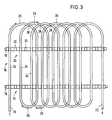
- the solution to the stated problem arises in an arrangement of the type mentioned in a surprisingly simple manner in that the arches between the ends of the strands run in the same direction of rotation and the back and forth arcs intersect so that the strand adjoining the advance is at a distance of several pockets of a rail and the adjoining next strand is at a distance from the advance has fewer pockets of a rail and that pockets remain free at the beginning and end of an arrangement. Since the arches run in the same direction between the ends of the strands and the back and forth arcs intersect, the strands can be inserted into each pocket of the rails and thus with a small mutual distance.
- one strand is placed in the sixth pocket, the next strand in the third pocket, the next strand in the eighth pocket, the next strand in the fifth pocket, etc.
- the successive strands are separated by several pockets and the arches connecting them have a relatively large radius, each pocket is occupied by one strand. This allows a lot of pipe to be accommodated in a small space. This results in a large transition area between the heat transfer medium, for example a coolant, and air in a narrow space.
- the arch facing the ceiling preferably lies in the plane of the spacer strips.
- the strand adjoining the lead is at a distance of five pockets of a rail and the adjoining strand is at a distance of two pockets of a rail from the lead.
- the strands themselves can run parallel to each other. Likewise, every second strand can run at an angle. Finally, the strands can have different distances from one another.
- rails are fastened in two levels under the ceiling. With this measure, even more pipe can be accommodated in a small space.
- the rails lying in different levels are expediently arranged so as to be longitudinally offset from one another by the length of a pocket. This avoids that the tubes of one level lie in the lee of the tubes of the other level. Air can flow around the tubes of the two levels in the same way. Spacer strips are expediently located between the individual rails.
- the mats should have such a volume that they have to be plugged into the space between the underside of the ceiling and the pipes with a little force. Then they lie on the pipes with a large surface area.
- FIG. 1 schematically shows a room with a floor, two walls and a ceiling 14.
- the pipes 16 carrying the coolant run at a distance below the underside of the ceiling 14.
- the spacer strips 18 are fastened directly to the ceiling 14. For example, they are pegged to the ceiling.
- the rails 20 are fastened to the spacer strips 18. As shown for example in FIG. 2, the rails 20 have pockets 22.
- the tubes 16 are held in these.
- wart-like projections are provided on the inside of the pockets 22, wart-like projections are provided. They prevent them from sliding down.
- FIG. 3 shows the particularly advantageous form of laying for the pipes 16 carrying the coolant. These lie in the pockets 22 with straight and parallel strands 24. Bends 26 connect the ends of the strands 24. The arrows drawn along the bends 26 show the same direction of rotation all arches. The arches intersect at the points 28. In the central region of the two rails 20 there is a tube 16 in each pocket 16. Adjacent strands 24 are thus only apart from one another by the distance 22. The narrowest radius, which is described by an arc 26 corresponds to the distance between three pockets. This means that the tubes 16 are bent only along a relatively large radius despite the narrow spacing between the individual strands 24.
- FIG. 3 also shows a flow 30 and a return 32. These feed the coolant in and out.
- Figures 4 to 6 show that spacer strips 18, rails 20 and tubes 16 are mounted in two levels one above the other under the ceiling 14. 4, the rails 20 are longitudinally offset from one another by the length of a pocket 22. This facilitates the air flowing around the tubes 16. 5 shows, the spacer strips 18 and the rails 20 are arranged directly below one another and connected to one another.
- porous and flexible mats 34 made of a material with high thermal conductivity rest on and over the two tube layers. In reality, the space between the two pipe layers and above the upper pipe layer can be filled with the mats more than is shown in FIG. 5. The mats 34 increase the surface area over which the heat is transferred from the air to the coolant.
Landscapes
- Engineering & Computer Science (AREA)
- Physics & Mathematics (AREA)
- Thermal Sciences (AREA)
- Chemical & Material Sciences (AREA)
- Combustion & Propulsion (AREA)
- Mechanical Engineering (AREA)
- General Engineering & Computer Science (AREA)
- Supports For Pipes And Cables (AREA)
- Air-Conditioning For Vehicles (AREA)
- Heat-Exchange Devices With Radiators And Conduit Assemblies (AREA)
Claims (11)
- Montage pour le maintien de moyens de transfert de chaleur, en particulier de tubes flexibles (16) parcourus par un fluide réfrigérant, en dessous du plafond (14) d'un local, comportant des lattes d'espacement (18) fixées sous ce plafond, des bandes en une matière plate présentant des créneaux (22) pour la mise en place et le maintien des moyens de transfert de chaleur (16) qui sont posés en des longueurs (24) s'étendant dans un sens et dans l'autre, séparées par une distance réciproque et raccordées par des coudes (26), et qui comprennent un aller (30) et un retour (32), caractérisé en ce que les coudes (26) s'étendent entre les extrémités des longueurs (24) dans le même sens de rotation et des coudes d'aller et de retour (26) se croisent, que la longueur (24) qui se raccorde à l'aller (30) présente, à l'égard de cet aller, une distance de plusieurs créneaux (22) d'une bande (20) et la longueur (24) suivante qui se raccorde à la précédente présente, à l'égard de l'aller (30), une distance d'un plus petit nombre de créneaux (22) d'une bande (20) et qu'au début et à la fin d'un montage, des créneaux (22) restent libres.
- Montage suivant la revendication 1, caractérisé en ce que, dans le cas de coudes (26) qui se croisent, le coude tourné vers le plafond (14) du local se trouve dans le plan des lattes d'espacement (18).
- Montage suivant la revendication 1, caractérisé en ce que la longueur (24) qui se raccorde à l'aller (30) présente, à l'égard de celui-ci, une distance de cinq créneaux (22) d'une bande (20) et la longueur (24) suivante qui se raccorde à la précédente présente, à l'égard de l'aller (30), une distance de deux créneaux (22) d'une bande (20).
- Montage suivant l'une quelconque des revendications 1 à 3, caractérisé en ce que les longueurs (24) s'étendent parallèlement l'une à l'autre.
- Montage suivant l'une quelconque des revendications 1 à 4, caractérisé en ce que chaque seconde longueur (24) s'étend obliquement.
- Montage suivant l'une quelconque des revendications 1 à 5, caractérisé en ce que les longueurs (24) présentent des distances réciproques différentes.
- Montage suivant l'une quelconque des revendications 1 à 6, caractérisé en ce que des bandes (20) sont fixées dans deux plans en dessous du plafond (14) du local.
- Montage suivant la revendication 7, caractérisé en ce que les bandes (20) sont décalées longitudinalement l'une par rapport à l'autre de la longueur d'un créneau (22).
- Montage suivant la revendication 7 ou 8, caractérisé en ce qu'une latte d'espacement (18) est installée entre chaque fois deux bandes (20).
- Montage suivant l'une quelconque des revendications 1 à 9, caractérisé en ce que des mats flexibles et poreux (34) en une matière à haute conductibilité thermique sont installés entre le plafond (14) du local et les tubes (16).
- Montage suivant la revendication 10, caractérisé en ce que les mats (34) ont un volume tel qu'ils sont au moins partiellement en contact avec les tubes (16).
Priority Applications (1)
| Application Number | Priority Date | Filing Date | Title |
|---|---|---|---|
| AT88120610T ATE80214T1 (de) | 1987-12-19 | 1988-12-09 | Anordnung zum halten eines waermetraegers unter einer raumdecke. |
Applications Claiming Priority (4)
| Application Number | Priority Date | Filing Date | Title |
|---|---|---|---|
| DE3743208 | 1987-12-19 | ||
| DE3743208 | 1987-12-19 | ||
| DE3814227A DE3814227A1 (de) | 1987-12-19 | 1988-04-27 | Anordnung zum halten von kuehlmittel-rohren unter einer raumdecke |
| DE3814227 | 1988-04-27 |
Publications (2)
| Publication Number | Publication Date |
|---|---|
| EP0321802A1 EP0321802A1 (fr) | 1989-06-28 |
| EP0321802B1 true EP0321802B1 (fr) | 1992-09-02 |
Family
ID=25862980
Family Applications (1)
| Application Number | Title | Priority Date | Filing Date |
|---|---|---|---|
| EP88120610A Expired - Lifetime EP0321802B1 (fr) | 1987-12-19 | 1988-12-09 | Montage d'un caloporteur sous le plafond d'un espace |
Country Status (2)
| Country | Link |
|---|---|
| EP (1) | EP0321802B1 (fr) |
| DE (2) | DE3814227A1 (fr) |
Families Citing this family (1)
| Publication number | Priority date | Publication date | Assignee | Title |
|---|---|---|---|---|
| DE4228721A1 (de) * | 1992-08-28 | 1994-03-03 | Wilhelmi Werke Gmbh & Co Kg | Verfahren zum Verkleiden einer Decke und Verkleidung nach diesem Verfahren |
Family Cites Families (5)
| Publication number | Priority date | Publication date | Assignee | Title |
|---|---|---|---|---|
| DE1604066A1 (de) * | 1966-01-28 | 1970-09-03 | Thyssen Rohrleitungsbau Gmbh | Deckenheizungs- oder -kuehlanlage |
| FR2225265B1 (fr) * | 1973-04-16 | 1976-05-07 | Cables De Lyon Geoffroy Delore | |
| DE2551089A1 (de) * | 1975-11-14 | 1977-05-18 | Burr Martin | Fussbodenheizung |
| DE8101301U1 (de) * | 1981-01-21 | 1981-08-20 | Feist, Artus, 5060 Bergisch Gladbach | Aus metallischem Flachmaterial bestehende Schiene zum Fixieren der Heizrohre einer Flächenheizung |
| DE8703788U1 (de) * | 1987-03-10 | 1987-05-07 | Feist, Artus, 5060 Bergisch Gladbach | Kühlplatte |
-
1988
- 1988-04-27 DE DE3814227A patent/DE3814227A1/de not_active Withdrawn
- 1988-12-09 EP EP88120610A patent/EP0321802B1/fr not_active Expired - Lifetime
- 1988-12-09 DE DE8888120610T patent/DE3874304D1/de not_active Expired - Lifetime
Also Published As
| Publication number | Publication date |
|---|---|
| DE3814227A1 (de) | 1989-06-29 |
| DE3874304D1 (de) | 1992-10-08 |
| EP0321802A1 (fr) | 1989-06-28 |
Similar Documents
| Publication | Publication Date | Title |
|---|---|---|
| DE2258157C2 (de) | Vorrichtung zur Erzeugung bzw. Aufrechterhaltung von Eisflächen | |
| DE69609517T2 (de) | Strukturierte packung | |
| DE1269144B (de) | Plattenwaermetauscher | |
| DE3305471A1 (de) | In einem fliessbett installierter waermetauscher | |
| EP2547977B1 (fr) | Echangeur de chaleut avec elément de retenue | |
| DE2313117A1 (de) | Einrichtung an einem waermeaustauscher | |
| EP2056024A1 (fr) | Chauffage de surface, notamment pour le chauffage au sol | |
| DE19623245C2 (de) | Wärmetauscher | |
| DE3723792A1 (de) | Raumdecke aus metallplatten | |
| EP2256419A2 (fr) | Elément de chauffage et/ou de refroidissement de surfaces | |
| DE4433392A1 (de) | Kunststoffrohrmatte zur Kühlung, Heizung und/oder zum Wärmeaustausch | |
| EP0321802A1 (fr) | Montage d'un caloporteur sous le plafond d'un espace | |
| DE2705526C3 (de) | Elektrisches Heizelement für gasförmige Medien | |
| DE2853043A1 (de) | Montageplatte mit oberseitigen haltenoppen fuer die heizrohre einer fussbodenheizung | |
| EP0699609A2 (fr) | Dispositif de recouvrement à longueur variable pour une machine à imprimer | |
| DE20017369U1 (de) | Betonkerntemperierungsmodule | |
| DE3234793A1 (de) | Fussbodenheizung | |
| DE2921406A1 (de) | Gitterrost fuer die rohre eines rohrbuendel-apparates, z.b. eines waermetauschers | |
| DE1941602A1 (de) | Blendschutzvorrichtung fuer Strassen | |
| DE1113209B (de) | Fraktioniervorrichtung | |
| CH671442A5 (fr) | ||
| CH662515A5 (en) | Built-in element for mass transfer columns | |
| CH671096A5 (fr) | ||
| DE3143241C2 (de) | Wärmetauschereinheit | |
| DE3027430A1 (de) | Plattenheizung |
Legal Events
| Date | Code | Title | Description |
|---|---|---|---|
| PUAI | Public reference made under article 153(3) epc to a published international application that has entered the european phase |
Free format text: ORIGINAL CODE: 0009012 |
|
| AK | Designated contracting states |
Kind code of ref document: A1 Designated state(s): AT BE CH DE FR GB IT LI LU |
|
| 17P | Request for examination filed |
Effective date: 19890726 |
|
| 17Q | First examination report despatched |
Effective date: 19900412 |
|
| GRAA | (expected) grant |
Free format text: ORIGINAL CODE: 0009210 |
|
| AK | Designated contracting states |
Kind code of ref document: B1 Designated state(s): AT BE CH DE FR GB IT LI LU |
|
| PG25 | Lapsed in a contracting state [announced via postgrant information from national office to epo] |
Ref country code: IT Free format text: LAPSE BECAUSE OF FAILURE TO SUBMIT A TRANSLATION OF THE DESCRIPTION OR TO PAY THE FEE WITHIN THE PRE;WARNING: LAPSES OF ITALIAN PATENTS WITH EFFECTIVE DATE BEFORE 2007 MAY HAVE OCCURRED AT ANY TIME BEFORE 2007. THE CORRECT EFFECTIVE DATE MAY BE DIFFERENT FROM THE ONE RECORDED.SCRIBED TIME-LIMIT Effective date: 19920902 Ref country code: GB Effective date: 19920902 Ref country code: FR Effective date: 19920902 Ref country code: BE Effective date: 19920902 |
|
| REF | Corresponds to: |
Ref document number: 80214 Country of ref document: AT Date of ref document: 19920915 Kind code of ref document: T |
|
| REF | Corresponds to: |
Ref document number: 3874304 Country of ref document: DE Date of ref document: 19921008 |
|
| PG25 | Lapsed in a contracting state [announced via postgrant information from national office to epo] |
Ref country code: AT Effective date: 19921209 |
|
| PG25 | Lapsed in a contracting state [announced via postgrant information from national office to epo] |
Ref country code: LU Free format text: LAPSE BECAUSE OF NON-PAYMENT OF DUE FEES Effective date: 19921231 Ref country code: LI Effective date: 19921231 Ref country code: CH Effective date: 19921231 |
|
| EN | Fr: translation not filed | ||
| GBV | Gb: ep patent (uk) treated as always having been void in accordance with gb section 77(7)/1977 [no translation filed] |
Effective date: 19920902 |
|
| PLBE | No opposition filed within time limit |
Free format text: ORIGINAL CODE: 0009261 |
|
| STAA | Information on the status of an ep patent application or granted ep patent |
Free format text: STATUS: NO OPPOSITION FILED WITHIN TIME LIMIT |
|
| 26N | No opposition filed | ||
| REG | Reference to a national code |
Ref country code: CH Ref legal event code: AUV Free format text: DAS OBENGENANNTE PATENT IST, MANGELS BEZAHLUNG DER 5.JAHRESGEBUEHR, GELOESCHT OWRDEN. Ref country code: CH Ref legal event code: PL |
|
| PGFP | Annual fee paid to national office [announced via postgrant information from national office to epo] |
Ref country code: DE Payment date: 19951221 Year of fee payment: 8 |
|
| PG25 | Lapsed in a contracting state [announced via postgrant information from national office to epo] |
Ref country code: DE Effective date: 19970902 |