EP0321825A2 - Rangée d'aubes rotoriques pour traversée axiale pour compresseurs ou turbines - Google Patents
Rangée d'aubes rotoriques pour traversée axiale pour compresseurs ou turbines Download PDFInfo
- Publication number
- EP0321825A2 EP0321825A2 EP88120768A EP88120768A EP0321825A2 EP 0321825 A2 EP0321825 A2 EP 0321825A2 EP 88120768 A EP88120768 A EP 88120768A EP 88120768 A EP88120768 A EP 88120768A EP 0321825 A2 EP0321825 A2 EP 0321825A2
- Authority
- EP
- European Patent Office
- Prior art keywords
- blades
- blade
- wheel disc
- rotor blade
- axial
- Prior art date
- Legal status (The legal status is an assumption and is not a legal conclusion. Google has not performed a legal analysis and makes no representation as to the accuracy of the status listed.)
- Granted
Links
Images


Classifications
-
- F—MECHANICAL ENGINEERING; LIGHTING; HEATING; WEAPONS; BLASTING
- F01—MACHINES OR ENGINES IN GENERAL; ENGINE PLANTS IN GENERAL; STEAM ENGINES
- F01D—NON-POSITIVE DISPLACEMENT MACHINES OR ENGINES, e.g. STEAM TURBINES
- F01D5/00—Blades; Blade-carrying members; Heating, heat-insulating, cooling or antivibration means on the blades or the members
- F01D5/30—Fixing blades to rotors; Blade roots ; Blade spacers
- F01D5/32—Locking, e.g. by final locking blades or keys
- F01D5/326—Locking of axial insertion type blades by other means
-
- F—MECHANICAL ENGINEERING; LIGHTING; HEATING; WEAPONS; BLASTING
- F01—MACHINES OR ENGINES IN GENERAL; ENGINE PLANTS IN GENERAL; STEAM ENGINES
- F01D—NON-POSITIVE DISPLACEMENT MACHINES OR ENGINES, e.g. STEAM TURBINES
- F01D11/00—Preventing or minimising internal leakage of working-fluid, e.g. between stages
- F01D11/005—Sealing means between non relatively rotating elements
- F01D11/006—Sealing the gap between rotor blades or blades and rotor
-
- F—MECHANICAL ENGINEERING; LIGHTING; HEATING; WEAPONS; BLASTING
- F01—MACHINES OR ENGINES IN GENERAL; ENGINE PLANTS IN GENERAL; STEAM ENGINES
- F01D—NON-POSITIVE DISPLACEMENT MACHINES OR ENGINES, e.g. STEAM TURBINES
- F01D5/00—Blades; Blade-carrying members; Heating, heat-insulating, cooling or antivibration means on the blades or the members
- F01D5/30—Fixing blades to rotors; Blade roots ; Blade spacers
- F01D5/3007—Fixing blades to rotors; Blade roots ; Blade spacers of axial insertion type
Definitions
- the invention relates to an axially flowed rotor blade grille according to the preamble of patent claim 1.
- Blade grates according to the type mentioned have proven themselves in practice, with regard to the control of the peripheral force and tension loads to be expected at relatively high speeds and centrifugal forces on the rotor and with regard to the achievability of a comparatively low wheel disc weight.
- FR-PS 12 07 772 It is also known from FR-PS 12 07 772 to provide a co-rotating cover disk at the front end of a turbine wheel disk.
- the cover disk together with the front wheel disk surface, should enclose a cooling air chamber which is acted upon from a suitable point on the turbine rotor by means of cooling air removed from the compressor of the engine.
- the cooling air is intended to flow along the wheel disc via the cooling air chamber mentioned and then to be supplied to the rotor blades to be cooled via corresponding coolant lines in the wheel disc and on or in the blade roots.
- the invention has for its object to provide a blade grille of the type mentioned, in which the blades are axially secured in a relatively simple manner in one direction on a wheel disc.
- the relevant length dimension of the respective blade feet can be assigned very precisely to the corresponding length dimension of the axial grooves or recesses in the wheel disk. In this way, the steps mentioned at the outset can be practically prevented, in particular in conjunction with a cover disk provided on the end face of the wheel disk for the cooling air guidance. In connection with the supply of cooling air to the blades, an optimal seal between the front cover plate and the relevant disk counter surface is achieved.
- Another important advantage of the invention is that neither precise machining of the root of the blades in question nor reworking of the disk is hindered, since neither circumferential grooves nor retaining lugs are necessary on the disk.
- cooling air supply from below is never hindered by the relevant feet of the rotor blades. Together with one or two cover disks, the cooling air supply to the turbine rotor blades from below through the foot from one or both sides of the wheel disk is thus possible without hindrance.
- the invention makes it possible to optimally seal the transition area in question between the bumps of the disks and the blade root plates without any particular additional outlay.
- this area there is the overlap of grinding contour and clearing contour, which will be identified later.
- the sealing point can be positioned anywhere without having to change the installation direction.
- the design is based on a change in the previously used clearing contour R of the rotor and the grinding contour S of the rotor blade. It is explained here, for example, in the context of a conventional two-tooth composite rotor blade, but without being bound to such a foot geometry.
- the relevant foot geometry can e.g. hammer head-like or as shown in Fig. 1,3,5 etc., pine cone or fir tree foot-like.
- the relevant grinding or contour contour S of the moving blade is smaller than the clearing contour R of the disk.
- the clearing contour R is always the outer one.
- the two contours do not overlap.
- the grinding or contour contour S should overlap with the clearing contour R of the disk 4 in the upper region N.
- FIG. 4 which will be explained in more detail below, is also used in this way without further corresponding digestion (component coverage N).
- a part of the disc humps 8 (FIG. 2) in question can be processed accordingly in the upper or outer region.
- the processing mentioned can be carried out, for example, by turning.
- the wheel disc 4 (FIG. 2) can also be produced from the outset in the sense of the required nominal size.
- the wheel disk 4 in question can be manufactured from the outset, for example, electrochemically or as part of a pressure sintering process in the context of the required nominal size or the precautions for the formation of the later webs 7, suitable surface finishing to the required nominal size being able to be carried out if necessary machining or grinding post-processing.
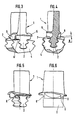
- FIGS. 2 to 6 In a more precise explanation of the subject matter of the invention, reference is first made to the exemplary embodiments according to FIGS. 2 to 6. It deals with an axially flowed rotor blade grille for a turbine of a gas turbine jet engine.
- the turbine blades 1 are to be held with their feet 2 in geometrically coordinated axial grooves 3 of a wheel disk 4 such that gaps extending in the axial and circumferential directions are formed between base plates 5 of the blades and wheel disk surface.
- component overlaps N are formed on the gaps between sections of the rotor blades 1 and the wheel disc 4 with which the blades 1 are axially fixed to the wheel disc 4 in one direction.
- the component sections can be formed by radial wall parts 6 of the base plates 5 and webs 7 of the wheel disk 4 projecting radially into the interspaces.
- the webs 7 in question are nose-shaped and each extend parallel to the front faces of the discs on the nasal bumps 8.
- the radial wall parts of the moving blades 1 in question can be provided with recesses 9 drawn in spatially inwards in order to enclose the relevant counter-sections of the webs 7, the Record wheel disc 4.
- each turbine blade 1 in question can have at least two axially spaced radial wall parts 6 and 6 ', which extend over the entire width of a base plate 5;
- each rotor blade 1 forms from the blade root and projects on both sides of the wheel disc surface in the circumferential direction Component surfaces, which are also formed as stop surfaces against the respective webs 7 on the wheel disc 4.
- the local coverage area N which can be seen in more detail in FIG. 4. The said coverage N of the two contours can be very small.
- the local coverage N is dependent on the sum of the tolerances at the respective mutual contact points, the centrifugal force and the thermal expansion of the blade, the deflection of the web 7 in question on the wheel disk 4 by axial forces and also depends on the surface pressure between the web 7 and the blade 1.
- Fig. 5 like Fig. 6 can also be seen that the respective front and rear end of the base plate 5 of each blade 1 projects beyond the relevant radial wall parts 6,6 'roof-shaped in the axial and circumferential directions.
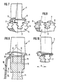
- FIGS. 7 and 8 is particularly characterized in that the aforementioned webs 7 on the wheel disc 4 here extend in the central circumferential area along the surfaces of the disc bumps 8 in question.
- a blade design can thus be represented, which forms a comparatively large axially projecting roof-shaped overhang over the base plate 5 at the downstream end. Accordingly, there is a comparatively narrow circumferential channel section between the two radial wall parts 6 and 6 ', locally above the wheel disc surface formed by the cusps 8.
- FIG. 9 illustrates the invention in terms of a cooled high pressure blade concept.
- the wheel disc 4 is associated with a rotating face plate 10, which is intended to axially fix the turbine blades 1 'located in the wheel disc 4 to be cooled, via their respective component sections on the webs 7 in the manner already explained in FIGS. 2 to 6 in both directions .
- the cover plate 10 sits on the end face on the relevant mating surfaces of the radial wall parts 6' and the bumps 8 (Fig.2) and the blade feet 2 on properly.
- the cover disk 10 forms a cooling air chamber 11 along the wheel disk 4, which is connected from the relevant blade root sides via suitable coolant lines 12, 13 (cooling air flow from F to F ') to the rotor blades 1' of the moving grate to be cooled.
- the chamber 11 is thus e.g. Air taken at the high-pressure compressor end, which is supplied via the hollow shaft system of the high-pressure compressor.
- FIGS. 11 to 14 differs from that according to FIGS. 2 to 6 in that at the rear end of the turbine blade 1, in the region of the rear wall part 6 and between the local end of the base plate 5 and foot 2, a relatively large-area recess 12 is formed, into which the webs 7 protrude locally (FIG. 13).
- cover disks shown in FIG. 9 instead of the cover disks shown in FIG. 9, other additional disk-shaped securing elements (co-rotating) can also be provided, which do not have to be related to a coolant guide chosen as an example in accordance with FIG. 9.
- FIG. 15 and 16 again illustrate a variant within the framework of the basic idea of the invention, here for example in the form of rearward engagement of the webs 7 in the relevant recesses 9 (see also FIG. 6), the rear radial wall parts 6 in question being snug rest against the webs 7.
- the blade root grooves 3 are each inclined at the same angles with respect to the disk axis in question.
- Such inclined or inclined grooves 3 are used as an example in all the previous embodiments.
- the axial or. Foot grooves could of course also be arranged parallel to the axis.
- FIG. 17 and 18 illustrate a variant of the invention, in which, for example, cooled turbine blades 1 'are provided and the component overlap provided for axial fixing on the wheel disk 4 between the front radial wall part 6 of the blade 1 and outer end faces 7' of the wheel disk 4 or the disc hump 8 is formed. Furthermore, FIG. 17 illustrates the assignment of a cover disk 10 equipped with a sealing labyrinth with regard to the coolant guidance (channels 11/12) into the blade 1 'similar to FIG. 9.
- exemplary playpen variants can also be designed such that the component overlaps form a local secondary flow seal with respect to the air flow in the compressor duct (compressor rotor blades) or with respect to the hot gas flow in the turbine duct (turbine rotor blades).
- the component overlaps can form a local cooling air shutoff seal with respect to the hot gas flow in the turbine, the gaps enclosed between base plates 5, radial wall parts 6, 6 'and wheel disk surface providing suitable cooling air flow into the cooling channels of the blades or the shovel blades should enable.
Landscapes
- Engineering & Computer Science (AREA)
- Mechanical Engineering (AREA)
- General Engineering & Computer Science (AREA)
- Turbine Rotor Nozzle Sealing (AREA)
- Structures Of Non-Positive Displacement Pumps (AREA)
- Sliding-Contact Bearings (AREA)
Applications Claiming Priority (2)
| Application Number | Priority Date | Filing Date | Title |
|---|---|---|---|
| DE3743253 | 1987-12-19 | ||
| DE19873743253 DE3743253A1 (de) | 1987-12-19 | 1987-12-19 | Axial durchstroemtes laufschaufelgitter fuer verdichter oder turbinen |
Publications (3)
| Publication Number | Publication Date |
|---|---|
| EP0321825A2 true EP0321825A2 (fr) | 1989-06-28 |
| EP0321825A3 EP0321825A3 (en) | 1989-08-30 |
| EP0321825B1 EP0321825B1 (fr) | 1992-12-16 |
Family
ID=6343084
Family Applications (1)
| Application Number | Title | Priority Date | Filing Date |
|---|---|---|---|
| EP88120768A Expired - Lifetime EP0321825B1 (fr) | 1987-12-19 | 1988-12-13 | Rangée d'aubes rotoriques pour traversée axiale pour compresseurs ou turbines |
Country Status (5)
| Country | Link |
|---|---|
| US (1) | US4940389A (fr) |
| EP (1) | EP0321825B1 (fr) |
| JP (1) | JP3120849B2 (fr) |
| DE (2) | DE3743253A1 (fr) |
| ES (1) | ES2036662T3 (fr) |
Cited By (1)
| Publication number | Priority date | Publication date | Assignee | Title |
|---|---|---|---|---|
| EP0475878A1 (fr) * | 1990-09-11 | 1992-03-18 | Pratt & Whitney Canada, Inc. | Dispositif de retenue axiale d'une pale de ventilateur |
Families Citing this family (21)
| Publication number | Priority date | Publication date | Assignee | Title |
|---|---|---|---|---|
| US5183389A (en) * | 1992-01-30 | 1993-02-02 | General Electric Company | Anti-rock blade tang |
| DE4203656C2 (de) * | 1992-02-08 | 2000-06-21 | Abb Patent Gmbh | Vorrichtung zur Herstellung von Axialnuten an Läuferscheiben eines Turbinenläufers |
| US5275536A (en) * | 1992-04-24 | 1994-01-04 | General Electric Company | Positioning system and impact indicator for gas turbine engine fan blades |
| US5271718A (en) * | 1992-08-11 | 1993-12-21 | General Electric Company | Lightweight platform blade |
| US5302086A (en) * | 1992-08-18 | 1994-04-12 | General Electric Company | Apparatus for retaining rotor blades |
| US5281098A (en) * | 1992-10-28 | 1994-01-25 | General Electric Company | Single ring blade retaining assembly |
| US5435694A (en) * | 1993-11-19 | 1995-07-25 | General Electric Company | Stress relieving mount for an axial blade |
| FR2856105B1 (fr) * | 2003-06-16 | 2007-05-25 | Snecma Moteurs | Amelioration de la capacite de retention d'une aube a attache marteau dissymetrique a l'aide des raidisseurs de plates-formes |
| US7507075B2 (en) † | 2005-08-15 | 2009-03-24 | United Technologies Corporation | Mistake proof identification feature for turbine blades |
| FR2900989B1 (fr) * | 2006-05-12 | 2008-07-11 | Snecma Sa | Ensemble pour compresseur de moteur d'aeronef comprenant des aubes a attache marteau a pied incline |
| EP1916389A1 (fr) * | 2006-10-26 | 2008-04-30 | Siemens Aktiengesellschaft | Assemblage d'aubes de turbine |
| JP2008144624A (ja) * | 2006-12-07 | 2008-06-26 | Ihi Corp | タービン動翼の固定構造 |
| US20080273982A1 (en) * | 2007-03-12 | 2008-11-06 | Honeywell International, Inc. | Blade attachment retention device |
| WO2009019126A1 (fr) | 2007-08-08 | 2009-02-12 | Alstom Technology Ltd | Agencement de rotor de turbine |
| FR2939834B1 (fr) | 2008-12-17 | 2016-02-19 | Turbomeca | Roue de turbine avec systeme de retention axiale des aubes |
| DE102009007664A1 (de) * | 2009-02-05 | 2010-08-12 | Mtu Aero Engines Gmbh | Abdichtvorrichtung an dem Schaufelschaft einer Rotorstufe einer axialen Strömungsmaschine |
| US9145772B2 (en) | 2012-01-31 | 2015-09-29 | United Technologies Corporation | Compressor disk bleed air scallops |
| US10458257B2 (en) | 2013-12-23 | 2019-10-29 | Safran Aircraft Engines | Blade comprising a shank, provided with a depressed portion |
| FR3015553B1 (fr) * | 2013-12-23 | 2019-05-31 | Safran Aircraft Engines | Aube comprenant une echasse, munie d'une seule portion en depression |
| GB202114773D0 (en) | 2021-10-15 | 2021-12-01 | Rolls Royce Plc | Bladed disc |
| GB202114772D0 (en) * | 2021-10-15 | 2021-12-01 | Rolls Royce Plc | Bladed disc |
Family Cites Families (22)
| Publication number | Priority date | Publication date | Assignee | Title |
|---|---|---|---|---|
| BE540433A (fr) * | 1954-08-12 | |||
| FR1138797A (fr) * | 1954-09-10 | 1957-06-19 | Henschel & Sohn Gmbh | Rotor pour turbine à gaz et à vapeur |
| FR1207772A (fr) * | 1957-07-18 | 1960-02-18 | Rolls Royce | Perfectionnements aux machines à fluide comportant des rotors à aubes |
| DE1051286B (de) * | 1958-06-02 | 1959-02-26 | Her Majesty The Queen In The R | Sicherung fuer eine in einer Axialnut einer Kreiselmaschine gehaltene Schaufel |
| US2972470A (en) * | 1958-11-03 | 1961-02-21 | Gen Motors Corp | Turbine construction |
| US3047268A (en) * | 1960-03-14 | 1962-07-31 | Stanley L Leavitt | Blade retention device |
| GB1093568A (en) * | 1965-11-23 | 1967-12-06 | Rolls Royce | Improvements in or relating to bladed rotors such as compressor rotors |
| US3378230A (en) * | 1966-12-16 | 1968-04-16 | Gen Electric | Mounting of blades in turbomachine rotors |
| DE6601212U (de) * | 1968-03-22 | 1969-02-27 | Siemens Ag | Laufschaufelbefestigung fuer turbomaschinen |
| GB1276100A (en) * | 1968-12-16 | 1972-06-01 | Rolls Royce | Bladed member for a fluid flow machine |
| GB1268911A (en) * | 1969-09-26 | 1972-03-29 | Rolls Royce | Improvements in or relating to blades |
| US3748060A (en) * | 1971-09-14 | 1973-07-24 | Westinghouse Electric Corp | Sideplate for turbine blade |
| US3923420A (en) * | 1973-04-30 | 1975-12-02 | Gen Electric | Blade platform with friction damping interlock |
| FR2358545A1 (fr) * | 1976-07-16 | 1978-02-10 | Snecma | Perfectionnements aux dispositifs d'equilibrage de rotors |
| US4221542A (en) * | 1977-12-27 | 1980-09-09 | General Electric Company | Segmented blade retainer |
| GB2042652B (en) * | 1979-02-21 | 1983-07-20 | Rolls Royce | Joint making packing |
| US4349318A (en) * | 1980-01-04 | 1982-09-14 | Avco Corporation | Boltless blade retainer for a turbine wheel |
| FR2507679A1 (fr) * | 1981-06-12 | 1982-12-17 | Snecma | Dispositif de verrouillage d'une aube de rotor de turbomachine |
| FR2524932A1 (fr) * | 1982-04-08 | 1983-10-14 | Snecma | Dispositif de retenue axiale de pieds d'aube dans un disque de turbomachine |
| JPS59226202A (ja) * | 1983-06-06 | 1984-12-19 | Toshiba Corp | タ−ビン動翼 |
| FR2585069B1 (fr) * | 1985-07-16 | 1989-06-09 | Snecma | Dispositif de limitation du debattement angulaire d'aubes montees sur un disque de rotor de turbomachine |
| JPS6247703U (fr) * | 1985-09-13 | 1987-03-24 |
-
1987
- 1987-12-19 DE DE19873743253 patent/DE3743253A1/de active Granted
-
1988
- 1988-12-07 US US07/281,201 patent/US4940389A/en not_active Expired - Lifetime
- 1988-12-08 JP JP63309012A patent/JP3120849B2/ja not_active Expired - Fee Related
- 1988-12-13 EP EP88120768A patent/EP0321825B1/fr not_active Expired - Lifetime
- 1988-12-13 DE DE8888120768T patent/DE3876768D1/de not_active Expired - Fee Related
- 1988-12-13 ES ES198888120768T patent/ES2036662T3/es not_active Expired - Lifetime
Cited By (1)
| Publication number | Priority date | Publication date | Assignee | Title |
|---|---|---|---|---|
| EP0475878A1 (fr) * | 1990-09-11 | 1992-03-18 | Pratt & Whitney Canada, Inc. | Dispositif de retenue axiale d'une pale de ventilateur |
Also Published As
| Publication number | Publication date |
|---|---|
| ES2036662T3 (es) | 1993-06-01 |
| JP3120849B2 (ja) | 2000-12-25 |
| US4940389A (en) | 1990-07-10 |
| DE3876768D1 (de) | 1993-01-28 |
| EP0321825A3 (en) | 1989-08-30 |
| DE3743253A1 (de) | 1989-06-29 |
| DE3743253C2 (fr) | 1991-04-25 |
| EP0321825B1 (fr) | 1992-12-16 |
| JPH01193005A (ja) | 1989-08-03 |
Similar Documents
| Publication | Publication Date | Title |
|---|---|---|
| EP0321825A2 (fr) | Rangée d'aubes rotoriques pour traversée axiale pour compresseurs ou turbines | |
| DE2952023C2 (fr) | ||
| DE69508201T2 (de) | Dichtungselement für die Schaufelplattformen eines Turbinenrotors | |
| DE2258618C2 (de) | Bolzenloser Schaufelhalter | |
| EP0214393B1 (fr) | Dispositif pour supprimer les vibrations des aubes de turbomachines | |
| DE3880873T2 (de) | Rotor-zusammenbau fuer eine turbomaschine. | |
| DE3117755C2 (de) | Dichtungsanordnung für Gasturbinentriebwerke | |
| DE2841793C2 (fr) | ||
| DE2908242C2 (de) | Rindförmiger Flansch für den Läufer einer axial durchströmten Strömungsmaschine zum Zusammenwirken mit einer Stirnfläche eines Radkranzes oder dergleichen | |
| DE3940607A1 (de) | Labyrinth-dichtungssystem | |
| EP3409897B1 (fr) | Agencement d'étanchéité pour une turbomachine, méthode de fabrication de l'agencement d'étanchéité et turbomachine | |
| DE10047307A1 (de) | Dichtungsanordnung | |
| DE60307100T2 (de) | Dichtungsanordnung für den rotor einer turbomaschine | |
| EP3999717B1 (fr) | Élément intermédiaire pour une connexion aube-disque de rotor pour le rotor d'une turbomachine, rotor pour une turbomachine et turbomachine | |
| EP1135578B1 (fr) | Dispositif d'appui pour pales de groupes moteurs | |
| EP1180197A1 (fr) | Systeme d'etancheite pour un rotor d'une turbomachine | |
| DE3148985C2 (de) | Rotorbaugruppe | |
| DE4108085A1 (de) | Laufschaufel fuer ein gasturbinentriebwerk | |
| DE3924829C2 (fr) | ||
| DE2853586C2 (de) | Laufradscheibe für Gasturbinenläufer mit Innengekühlten Schaufeln | |
| DE60023884T2 (de) | Vorrichtung zur regelung der luftströmung in einer turbinenschaufel | |
| DE4215440A1 (de) | Einrichtung zur Bauteilabdichtung, insbesondere bei Turbomaschinen | |
| DE3601911C2 (de) | Schaufelreihe | |
| EP0610668A1 (fr) | Dispositif pour le verrouillage d'aubes de rotor à entrée axiale et pour l'élimination du déséquilibre du rotor | |
| DE102016107315A1 (de) | Rotor mit Überhang an Laufschaufeln für ein Sicherungselement |
Legal Events
| Date | Code | Title | Description |
|---|---|---|---|
| PUAI | Public reference made under article 153(3) epc to a published international application that has entered the european phase |
Free format text: ORIGINAL CODE: 0009012 |
|
| AK | Designated contracting states |
Kind code of ref document: A2 Designated state(s): DE ES FR GB IT SE |
|
| PUAL | Search report despatched |
Free format text: ORIGINAL CODE: 0009013 |
|
| AK | Designated contracting states |
Kind code of ref document: A3 Designated state(s): DE ES FR GB IT SE |
|
| 17P | Request for examination filed |
Effective date: 19890902 |
|
| 17Q | First examination report despatched |
Effective date: 19900823 |
|
| GRAA | (expected) grant |
Free format text: ORIGINAL CODE: 0009210 |
|
| AK | Designated contracting states |
Kind code of ref document: B1 Designated state(s): DE ES FR GB IT SE |
|
| ET | Fr: translation filed | ||
| REF | Corresponds to: |
Ref document number: 3876768 Country of ref document: DE Date of ref document: 19930128 |
|
| ITF | It: translation for a ep patent filed | ||
| GBT | Gb: translation of ep patent filed (gb section 77(6)(a)/1977) |
Effective date: 19930317 |
|
| REG | Reference to a national code |
Ref country code: ES Ref legal event code: FG2A Ref document number: 2036662 Country of ref document: ES Kind code of ref document: T3 |
|
| PLBE | No opposition filed within time limit |
Free format text: ORIGINAL CODE: 0009261 |
|
| STAA | Information on the status of an ep patent application or granted ep patent |
Free format text: STATUS: NO OPPOSITION FILED WITHIN TIME LIMIT |
|
| 26N | No opposition filed | ||
| EAL | Se: european patent in force in sweden |
Ref document number: 88120768.2 |
|
| REG | Reference to a national code |
Ref country code: GB Ref legal event code: IF02 |
|
| PGFP | Annual fee paid to national office [announced via postgrant information from national office to epo] |
Ref country code: SE Payment date: 20041209 Year of fee payment: 17 |
|
| PGFP | Annual fee paid to national office [announced via postgrant information from national office to epo] |
Ref country code: ES Payment date: 20041215 Year of fee payment: 17 |
|
| PG25 | Lapsed in a contracting state [announced via postgrant information from national office to epo] |
Ref country code: IT Free format text: LAPSE BECAUSE OF NON-PAYMENT OF DUE FEES;WARNING: LAPSES OF ITALIAN PATENTS WITH EFFECTIVE DATE BEFORE 2007 MAY HAVE OCCURRED AT ANY TIME BEFORE 2007. THE CORRECT EFFECTIVE DATE MAY BE DIFFERENT FROM THE ONE RECORDED. Effective date: 20051213 |
|
| PG25 | Lapsed in a contracting state [announced via postgrant information from national office to epo] |
Ref country code: SE Free format text: LAPSE BECAUSE OF NON-PAYMENT OF DUE FEES Effective date: 20051214 Ref country code: ES Free format text: LAPSE BECAUSE OF NON-PAYMENT OF DUE FEES Effective date: 20051214 |
|
| EUG | Se: european patent has lapsed | ||
| PGFP | Annual fee paid to national office [announced via postgrant information from national office to epo] |
Ref country code: DE Payment date: 20061218 Year of fee payment: 19 |
|
| PGFP | Annual fee paid to national office [announced via postgrant information from national office to epo] |
Ref country code: GB Payment date: 20061221 Year of fee payment: 19 |
|
| REG | Reference to a national code |
Ref country code: ES Ref legal event code: FD2A Effective date: 20051214 |
|
| PGFP | Annual fee paid to national office [announced via postgrant information from national office to epo] |
Ref country code: FR Payment date: 20061212 Year of fee payment: 19 |
|
| GBPC | Gb: european patent ceased through non-payment of renewal fee |
Effective date: 20071213 |
|
| PG25 | Lapsed in a contracting state [announced via postgrant information from national office to epo] |
Ref country code: DE Free format text: LAPSE BECAUSE OF NON-PAYMENT OF DUE FEES Effective date: 20080701 |
|
| REG | Reference to a national code |
Ref country code: FR Ref legal event code: ST Effective date: 20081020 |
|
| PG25 | Lapsed in a contracting state [announced via postgrant information from national office to epo] |
Ref country code: GB Free format text: LAPSE BECAUSE OF NON-PAYMENT OF DUE FEES Effective date: 20071213 |
|
| PG25 | Lapsed in a contracting state [announced via postgrant information from national office to epo] |
Ref country code: FR Free format text: LAPSE BECAUSE OF NON-PAYMENT OF DUE FEES Effective date: 20071231 |