EP0321874A2 - Dispositif pour le montage d'un boîtier dans une ouverture d'un tableau ou d'un panneau mosaique - Google Patents
Dispositif pour le montage d'un boîtier dans une ouverture d'un tableau ou d'un panneau mosaique Download PDFInfo
- Publication number
- EP0321874A2 EP0321874A2 EP88121079A EP88121079A EP0321874A2 EP 0321874 A2 EP0321874 A2 EP 0321874A2 EP 88121079 A EP88121079 A EP 88121079A EP 88121079 A EP88121079 A EP 88121079A EP 0321874 A2 EP0321874 A2 EP 0321874A2
- Authority
- EP
- European Patent Office
- Prior art keywords
- housing
- wall
- spring element
- side wall
- spring
- Prior art date
- Legal status (The legal status is an assumption and is not a legal conclusion. Google has not performed a legal analysis and makes no representation as to the accuracy of the status listed.)
- Granted
Links
- 230000037431 insertion Effects 0.000 claims abstract description 15
- 238000003780 insertion Methods 0.000 claims abstract description 15
- 230000007423 decrease Effects 0.000 claims abstract description 3
- 230000003014 reinforcing effect Effects 0.000 claims description 2
- 229910001369 Brass Inorganic materials 0.000 description 2
- 239000010951 brass Substances 0.000 description 2
- 238000004026 adhesive bonding Methods 0.000 description 1
- 230000001276 controlling effect Effects 0.000 description 1
- 238000004519 manufacturing process Methods 0.000 description 1
- 230000001105 regulatory effect Effects 0.000 description 1
- 230000002787 reinforcement Effects 0.000 description 1
Images

Classifications
-
- H—ELECTRICITY
- H02—GENERATION; CONVERSION OR DISTRIBUTION OF ELECTRIC POWER
- H02B—BOARDS, SUBSTATIONS OR SWITCHING ARRANGEMENTS FOR THE SUPPLY OR DISTRIBUTION OF ELECTRIC POWER
- H02B1/00—Frameworks, boards, panels, desks, casings; Details of substations or switching arrangements
- H02B1/015—Boards, panels, desks; Parts thereof or accessories therefor
- H02B1/04—Mounting thereon of switches or of other devices in general, the switch or device having, or being without, casing
- H02B1/044—Mounting through openings
- H02B1/048—Snap mounting
Definitions
- the invention relates to a device for fastening housings in openings in a receiving wall, for example a control panel wall or a grid system wall, according to the preamble of claim 1.
- the housings are preferably so-called MCR devices, ie devices for measuring, controlling and regulating.
- MCR devices ie devices for measuring, controlling and regulating.
- Such a housing is known from DE-GM 87 04 506.
- the spring element consists of an elongated flat spring plate from which resilient webs are bent out.
- two brass cones are embedded in the housing wall, the base of which protrudes upwards from the housing side wall.
- Appropriately dimensioned elongated holes are provided in the spring plate with which the spring plate can be pushed under the protruding parts of the cone.
- the invention has for its object to provide a fastening device for a housing of the aforementioned type, which also allows simple and good attachment in a wall opening, but which is significantly easier and cheaper to manufacture.
- the housing with the fastening device according to the invention is pushed into the receiving wall from the front and is held sufficiently firmly in the opening of the receiving wall by the spring elements.
- the spring element in the fastening device according to the invention can be made from one part, and preferably from plastic, which is simply pressed with its pins into corresponding holes in the housing wall.
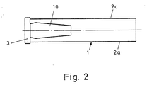
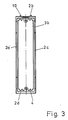
- Figures 1 to 3 show a plastic MSR known per se, which consists of four side walls 2a to 2d, a rear wall, not shown, a front side, not shown, and a front frame, not shown, attachable to the front.
- the two narrow opposite side walls are provided on their inside with webs 4 running in the direction from the front to the back, between which grooves for receiving inserts, printed circuit boards and the like are formed.
- the housing is pushed in the direction of arrow 19 shown in FIG. 1 into the opening of, for example, a control panel, the wall 20 of which is indicated in FIG. 1.
- a receiving wall for the housing is a grid system wall which consists of a plurality of vertical and horizontal walls which can be plugged together according to a grid system, the wall planes of which are parallel to the insertion direction of arrow 19 in FIG. 1.
- the opening in the receiving wall is dimensioned such that the housing lies with the edge 3a (FIG. 1) of a reinforcing strip 3 running around the front of the housing against the front boundary of the receiving opening.
- recesses 3b can also be seen in FIGS. 1 and 3, into which the front frame, not shown, which can be fitted from the front, engages with corresponding projections.
- a spring element according to the invention is fastened to the two opposite narrow side walls 2b, 2d for fastening the housing in the receiving wall.
- Figure 1 is the lower attachment point for a spring element is shown in partial section and without the spring element inserted.
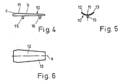
- the structure of the spring element is best seen in FIGS. 4 to 6.
- the spring element consists of a curved, resilient plate 11, on the underside of which faces the housing side wall there are two pins 15 and 16 aligned in the direction of insertion of the housing.
- the resilient plate is constructed symmetrically with respect to an axis of symmetry a coinciding with the insertion direction and actually or approximately touches the housing wall along this axis of symmetry.
- Spring flanges 12 and 13 extend to both sides of this axis of symmetry with increasing distance from the housing side wall. Since the thin plate has good spring properties, these spring flanges can be bent down perpendicular to the surface of the housing wall, and the resilient spring force can be influenced by a corresponding thickness of the plate.
- the resilient plate 11 is constructed in such a way that, viewed in the direction of view from the end of the housing, the elevation of the spring element over the housing wall is initially very small, then gradually increases continuously (region b) and in the front region c again to a certain one Value decreases.
- the area occupied by the resilient plate in the non-deformed state is preferably a section of the outer wall of a circular cylinder or an ellipse cylinder.
- two fastening pins 15, 16 are provided on the underside of the spring element, with which the spring element can be inserted into corresponding bores 15a, 16a (FIG. 1).
- the holes can pass through the housing wall or be designed as blind holes.
- the attachment can be done by gluing or by pressing in the pins dimensioned with the appropriate press or fit.
- the spring element does not prevent the housing from being inserted into the opening in the receiving wall.
- the edge of the receiving opening in the wall 20 (FIG. 1) meets the continuously increasing spring flanges 12, 13 and presses them down towards the housing wall.
- a force component which pulls the housing into the housing wall is generated by the spring elements.
- FIG. 1 and FIG. 4 shows, the height of the spring element 10 in the inserted state (FIG. 1) is lower than in the non-inserted state, since the spring element is pretensioned by the wall 20 and is thereby pressed flat.
- the spring element described in the figures can be modified in many ways.
- a symmetrical structure as described is not mandatory.
- the spring element can also be designed with only one spring flange.
- the change in height of the spring element in the direction of insertion need not be linear.
- a single fastening pin is also sufficient, and fastening pins of different sizes can also be provided.
- the fastening device according to the invention can be used particularly advantageously in those housings in which the housing side to be equipped with the fastening element is very narrow.
- the width of the fastening element 10 can be of the order of 1 cm.
Landscapes
- Engineering & Computer Science (AREA)
- Power Engineering (AREA)
- Casings For Electric Apparatus (AREA)
- Patch Boards (AREA)
- Springs (AREA)
- Power-Operated Mechanisms For Wings (AREA)
Priority Applications (1)
| Application Number | Priority Date | Filing Date | Title |
|---|---|---|---|
| AT88121079T ATE94316T1 (de) | 1987-12-21 | 1988-12-16 | Vorrichtung zur befestigung von gehaeusen in oeffnungen einer schalttafel oder einer rastersystemwand. |
Applications Claiming Priority (2)
| Application Number | Priority Date | Filing Date | Title |
|---|---|---|---|
| DE8716784U DE8716784U1 (de) | 1987-12-21 | 1987-12-21 | Vorrichtung zur Befestigung von Gehäusen in Öffnungen einer Schalttafel oder einer Rastersystemwand |
| DE8716784U | 1987-12-21 |
Publications (3)
| Publication Number | Publication Date |
|---|---|
| EP0321874A2 true EP0321874A2 (fr) | 1989-06-28 |
| EP0321874A3 EP0321874A3 (en) | 1989-10-18 |
| EP0321874B1 EP0321874B1 (fr) | 1993-09-08 |
Family
ID=6815326
Family Applications (1)
| Application Number | Title | Priority Date | Filing Date |
|---|---|---|---|
| EP88121079A Expired - Lifetime EP0321874B1 (fr) | 1987-12-21 | 1988-12-16 | Dispositif pour le montage d'un boîtier dans une ouverture d'un tableau ou d'un panneau mosaique |
Country Status (3)
| Country | Link |
|---|---|
| EP (1) | EP0321874B1 (fr) |
| AT (1) | ATE94316T1 (fr) |
| DE (2) | DE8716784U1 (fr) |
Cited By (1)
| Publication number | Priority date | Publication date | Assignee | Title |
|---|---|---|---|---|
| CN114566894A (zh) * | 2021-11-24 | 2022-05-31 | 国网甘肃省电力公司 | 一种变电站开关柜开关状态视频识别装置 |
Family Cites Families (3)
| Publication number | Priority date | Publication date | Assignee | Title |
|---|---|---|---|---|
| CH401629A (de) * | 1962-08-28 | 1965-10-31 | Georg Dr Hauser | Vorrichtung an einem Einbauelement zum Befestigen des Elementes an einer Tragplatte oder dergleichen |
| DE2120556A1 (de) * | 1971-04-27 | 1972-11-09 | Mon'tz K. Juchheim Thermometerfabrik, 6400 Fulda | Instrumentbefestigung an Schalttafeln od. dgl. mittels an der Gehäusewand angeordneten Klemmfederblechen |
| DE2628750C3 (de) * | 1976-06-25 | 1979-11-22 | Neuberger Messinstrumente Kg, 8000 Muenchen | In einer Tafelöffnung anzuordnendes MeBinstrumentengehäuse mit federnden Befestigungsklemmen |
-
1987
- 1987-12-21 DE DE8716784U patent/DE8716784U1/de not_active Expired
-
1988
- 1988-12-16 EP EP88121079A patent/EP0321874B1/fr not_active Expired - Lifetime
- 1988-12-16 DE DE88121079T patent/DE3883942D1/de not_active Expired - Fee Related
- 1988-12-16 AT AT88121079T patent/ATE94316T1/de not_active IP Right Cessation
Cited By (1)
| Publication number | Priority date | Publication date | Assignee | Title |
|---|---|---|---|---|
| CN114566894A (zh) * | 2021-11-24 | 2022-05-31 | 国网甘肃省电力公司 | 一种变电站开关柜开关状态视频识别装置 |
Also Published As
| Publication number | Publication date |
|---|---|
| EP0321874A3 (en) | 1989-10-18 |
| DE3883942D1 (de) | 1993-10-14 |
| ATE94316T1 (de) | 1993-09-15 |
| EP0321874B1 (fr) | 1993-09-08 |
| DE8716784U1 (de) | 1988-03-31 |
Similar Documents
| Publication | Publication Date | Title |
|---|---|---|
| DE2064443C3 (de) | Anordnung zum Befestigen eines langgestreckten Gegenstands an einem paralellen Gegenstand, insbesondere zum Verbinden von Flugzeugwandverkleidungen | |
| DE69121270T2 (de) | Zweiteilige Buchseneinheit für modularen Steckeraufbau | |
| DE3924048A1 (de) | Mutterartiger kunststoffbefestiger | |
| DE20321662U1 (de) | Kühlgerät | |
| DE3709970C2 (fr) | ||
| DE69308797T2 (de) | Geräteträger anzubringen auf einen Kabelkanal mit einander gegenüberliegenden Vorsprüngen | |
| DE9209519U1 (de) | HF-dichter Baugruppenträger | |
| EP0315936A1 (fr) | Cales pour supporter des vitrages ou similaires | |
| DE19738504C5 (de) | Tür für ein Haushaltsgerät, insbesondere einen Haushaltsgarofen | |
| DE20206813U1 (de) | Eckverbindungsvorrichtung zum Aufbau eines Gehäuserahmens oder eines Gehäuses sowie Gehäuserahmen oder Gehäuse | |
| CH652269A5 (en) | Quick mounting base made of plastic, for fixing an electrical device or printed-circuit board | |
| EP0321874B1 (fr) | Dispositif pour le montage d'un boîtier dans une ouverture d'un tableau ou d'un panneau mosaique | |
| DE2208289C2 (de) | Belüftungsvorrichtung | |
| DE29508292U1 (de) | Befehlsgerät | |
| DE3629002C2 (fr) | ||
| EP0871271B1 (fr) | Dispositif de montage pour une boítier de connexion électrique | |
| DE8704506U1 (de) | Vorrichtung zur Befestigung von Gehäusen in Öffnungen einer Schalttafel oder einer Rastersystemwand | |
| DE7702843U1 (de) | Fuehrungsschiene | |
| DE2255185C3 (de) | Befestigungselement für elektrische Anschlußeinheiten | |
| DE60106388T2 (de) | Verdeckte vorrichtung zur befestigung eines wandelementes | |
| EP0752744A1 (fr) | Composant électrique | |
| CH653793A5 (de) | Halter fuer nummerntafel. | |
| DE3007608C2 (de) | Vorrichtung zum Halten von Gegenständen | |
| DE2952655C2 (de) | Fadenführerbefestigung bei Kettenwirkmaschinen | |
| DE29623048U1 (de) | Halteklammer zur Befestigung mindestens zweier ebener Bauteile aneinander |
Legal Events
| Date | Code | Title | Description |
|---|---|---|---|
| PUAI | Public reference made under article 153(3) epc to a published international application that has entered the european phase |
Free format text: ORIGINAL CODE: 0009012 |
|
| AK | Designated contracting states |
Kind code of ref document: A2 Designated state(s): AT BE CH DE ES FR GB GR IT LI LU NL SE |
|
| PUAL | Search report despatched |
Free format text: ORIGINAL CODE: 0009013 |
|
| AK | Designated contracting states |
Kind code of ref document: A3 Designated state(s): AT BE CH DE ES FR GB GR IT LI LU NL SE |
|
| 17P | Request for examination filed |
Effective date: 19900313 |
|
| 17Q | First examination report despatched |
Effective date: 19920212 |
|
| GRAA | (expected) grant |
Free format text: ORIGINAL CODE: 0009210 |
|
| AK | Designated contracting states |
Kind code of ref document: B1 Designated state(s): AT BE CH DE ES FR GB GR IT LI LU NL SE |
|
| PG25 | Lapsed in a contracting state [announced via postgrant information from national office to epo] |
Ref country code: IT Free format text: LAPSE BECAUSE OF FAILURE TO SUBMIT A TRANSLATION OF THE DESCRIPTION OR TO PAY THE FEE WITHIN THE PRE;WARNING: LAPSES OF ITALIAN PATENTS WITH EFFECTIVE DATE BEFORE 2007 MAY HAVE OCCURRED AT ANY TIME BEFORE 2007. THE CORRECT EFFECTIVE DATE MAY BE DIFFERENT FROM THE ONE RECORDED.SCRIBED TIME-LIMIT Effective date: 19930908 Ref country code: NL Effective date: 19930908 Ref country code: SE Effective date: 19930908 Ref country code: BE Effective date: 19930908 Ref country code: GB Effective date: 19930908 Ref country code: ES Free format text: THE PATENT HAS BEEN ANNULLED BY A DECISION OF A NATIONAL AUTHORITY Effective date: 19930908 Ref country code: GR Free format text: LAPSE BECAUSE OF FAILURE TO SUBMIT A TRANSLATION OF THE DESCRIPTION OR TO PAY THE FEE WITHIN THE PRESCRIBED TIME-LIMIT Effective date: 19930908 |
|
| REF | Corresponds to: |
Ref document number: 94316 Country of ref document: AT Date of ref document: 19930915 Kind code of ref document: T |
|
| REF | Corresponds to: |
Ref document number: 3883942 Country of ref document: DE Date of ref document: 19931014 |
|
| PG25 | Lapsed in a contracting state [announced via postgrant information from national office to epo] |
Ref country code: AT Effective date: 19931216 |
|
| ET | Fr: translation filed | ||
| PG25 | Lapsed in a contracting state [announced via postgrant information from national office to epo] |
Ref country code: CH Effective date: 19931231 Ref country code: LU Free format text: LAPSE BECAUSE OF NON-PAYMENT OF DUE FEES Effective date: 19931231 Ref country code: LI Effective date: 19931231 |
|
| NLV1 | Nl: lapsed or annulled due to failure to fulfill the requirements of art. 29p and 29m of the patents act | ||
| GBV | Gb: ep patent (uk) treated as always having been void in accordance with gb section 77(7)/1977 [no translation filed] |
Effective date: 19930908 |
|
| PLBE | No opposition filed within time limit |
Free format text: ORIGINAL CODE: 0009261 |
|
| STAA | Information on the status of an ep patent application or granted ep patent |
Free format text: STATUS: NO OPPOSITION FILED WITHIN TIME LIMIT |
|
| 26N | No opposition filed | ||
| PG25 | Lapsed in a contracting state [announced via postgrant information from national office to epo] |
Ref country code: FR Effective date: 19940831 |
|
| REG | Reference to a national code |
Ref country code: CH Ref legal event code: PL |
|
| REG | Reference to a national code |
Ref country code: FR Ref legal event code: ST |
|
| PGFP | Annual fee paid to national office [announced via postgrant information from national office to epo] |
Ref country code: DE Payment date: 20030404 Year of fee payment: 15 |
|
| PG25 | Lapsed in a contracting state [announced via postgrant information from national office to epo] |
Ref country code: DE Free format text: LAPSE BECAUSE OF NON-PAYMENT OF DUE FEES Effective date: 20040701 |