EP0321921B1 - Variateur continu de vitesse avec dispositif de poulie à diamètre variable - Google Patents
Variateur continu de vitesse avec dispositif de poulie à diamètre variable Download PDFInfo
- Publication number
- EP0321921B1 EP0321921B1 EP88121286A EP88121286A EP0321921B1 EP 0321921 B1 EP0321921 B1 EP 0321921B1 EP 88121286 A EP88121286 A EP 88121286A EP 88121286 A EP88121286 A EP 88121286A EP 0321921 B1 EP0321921 B1 EP 0321921B1
- Authority
- EP
- European Patent Office
- Prior art keywords
- fluid
- secondary shaft
- shaft
- pulley
- cone
- Prior art date
- Legal status (The legal status is an assumption and is not a legal conclusion. Google has not performed a legal analysis and makes no representation as to the accuracy of the status listed.)
- Expired - Lifetime
Links
- 230000005540 biological transmission Effects 0.000 title claims description 50
- 239000012530 fluid Substances 0.000 claims description 84
- 238000005461 lubrication Methods 0.000 claims description 9
- 238000006073 displacement reaction Methods 0.000 claims description 8
- 238000005192 partition Methods 0.000 claims description 8
- 230000007246 mechanism Effects 0.000 description 9
- 230000001050 lubricating effect Effects 0.000 description 7
- 230000001143 conditioned effect Effects 0.000 description 5
- 239000000843 powder Substances 0.000 description 3
- 230000009467 reduction Effects 0.000 description 3
- 230000004907 flux Effects 0.000 description 2
- 239000002923 metal particle Substances 0.000 description 2
- 230000008859 change Effects 0.000 description 1
- 230000006835 compression Effects 0.000 description 1
- 238000007906 compression Methods 0.000 description 1
- 230000008878 coupling Effects 0.000 description 1
- 238000010168 coupling process Methods 0.000 description 1
- 238000005859 coupling reaction Methods 0.000 description 1
- 230000007423 decrease Effects 0.000 description 1
- 230000005347 demagnetization Effects 0.000 description 1
- 239000002184 metal Substances 0.000 description 1
- 230000007935 neutral effect Effects 0.000 description 1
- 239000002245 particle Substances 0.000 description 1
Images


Classifications
-
- F—MECHANICAL ENGINEERING; LIGHTING; HEATING; WEAPONS; BLASTING
- F16—ENGINEERING ELEMENTS AND UNITS; GENERAL MEASURES FOR PRODUCING AND MAINTAINING EFFECTIVE FUNCTIONING OF MACHINES OR INSTALLATIONS; THERMAL INSULATION IN GENERAL
- F16H—GEARING
- F16H61/00—Control functions within control units of change-speed- or reversing-gearings for conveying rotary motion ; Control of exclusively fluid gearing, friction gearing, gearings with endless flexible members or other particular types of gearing
- F16H61/66—Control functions within control units of change-speed- or reversing-gearings for conveying rotary motion ; Control of exclusively fluid gearing, friction gearing, gearings with endless flexible members or other particular types of gearing specially adapted for continuously variable gearings
- F16H61/662—Control functions within control units of change-speed- or reversing-gearings for conveying rotary motion ; Control of exclusively fluid gearing, friction gearing, gearings with endless flexible members or other particular types of gearing specially adapted for continuously variable gearings with endless flexible members
- F16H61/66272—Control functions within control units of change-speed- or reversing-gearings for conveying rotary motion ; Control of exclusively fluid gearing, friction gearing, gearings with endless flexible members or other particular types of gearing specially adapted for continuously variable gearings with endless flexible members characterised by means for controlling the torque transmitting capability of the gearing
-
- F—MECHANICAL ENGINEERING; LIGHTING; HEATING; WEAPONS; BLASTING
- F16—ENGINEERING ELEMENTS AND UNITS; GENERAL MEASURES FOR PRODUCING AND MAINTAINING EFFECTIVE FUNCTIONING OF MACHINES OR INSTALLATIONS; THERMAL INSULATION IN GENERAL
- F16H—GEARING
- F16H55/00—Elements with teeth or friction surfaces for conveying motion; Worms, pulleys or sheaves for gearing mechanisms
- F16H55/32—Friction members
- F16H55/52—Pulleys or friction discs of adjustable construction
- F16H55/56—Pulleys or friction discs of adjustable construction of which the bearing parts are relatively axially adjustable
-
- F—MECHANICAL ENGINEERING; LIGHTING; HEATING; WEAPONS; BLASTING
- F16—ENGINEERING ELEMENTS AND UNITS; GENERAL MEASURES FOR PRODUCING AND MAINTAINING EFFECTIVE FUNCTIONING OF MACHINES OR INSTALLATIONS; THERMAL INSULATION IN GENERAL
- F16H—GEARING
- F16H57/00—General details of gearing
- F16H57/04—Features relating to lubrication or cooling or heating
- F16H57/0434—Features relating to lubrication or cooling or heating relating to lubrication supply, e.g. pumps; Pressure control
Definitions
- This invention relates to transmissions, to infinitely variable speed transmissions, and to belt transmissions well suited for vehicular use, among other applications. More specifically, the invention deals with improvements in or relating to variable diameter pulley systems included in belt transmissions, particularly to the driven pulley and hydraulic circuit means associated therewith as defined in the first part of claim 1 and known for instance from US-A 4 494 942.
- Belt transmissions have been known and used extensively on motor vehicles. They include a variable diameter pulley system comprising a drive pulley on a transmission main shaft (primary shaft) and a driven pulley on a countershaft (secondary shaft), with a V-belt extending around the two pulleys.
- Each V-groove pulley is divided into a pair of halves known as pulley cones.
- One of the pulley cones is axially displaceable towards and away from the other in order to controllably vary the effective diameter of the pulley. Hydraulic fluid pressure is usually employed for controlling the axial position of the movable pulley cone with respect to the fixed pulley cone.
- This prior application teaches to direct the outflow of hydraulic fluid from a torque converter into the counterbalance chamber.
- An objection to this scheme is that it is applicable only to transmissions of the class incorporating a hydraulic torque converter. Additionally, the outflow from the torque converter cannot possibly be passed through a fluid cooler prior to introduction into the counterbalance chamber.
- Japanese Laid Open Patent Application No. 60-104848 teaches to form a counterbalance chamber providing a tubular member which concentrically surrounds the countershaft and the counterbalance chamber is slidably held against the back of a member defining the actuation chamber.
- This prior art device has the weakness that the area occurring centrifugal force in the counterbalance chamber is always of the smaller size than the area of the actuation chamber and so may therefore fail to develop a sufficient counterbalancing force.
- the counterbalance chamber must be of sufficient capacity to enable the fluid therein to counteract the centrifugal force of the fluid in the actuation chamber. No less important, however, is the fact that the hydraulic fluid be infallibly fed into the counterbalance chamber whenever the need arises for cancelling the centrifugal force of the fluid in the actuation chamber. It is undesirable that, as in the second recited prior art device, part of the mainline fluid be directed into the counterbalance chamber, in view of consequent changes in the mainline pressure fed to other parts of the transmission.
- the counterbalance chamber should be fed from some source of fluid pressure different from the source of mainline pressure.
- Belt transmissions of the type in question have had another problem that, as far as the applicant is aware, has been left unsolved.
- the countershaft with the driven pulley thereon is disposed considerably above the level of the transmission main shaft having the drive pulley mounted thereon, because of design requirements such as the large pulley diameters for a wide range of speed ratios obtainable and the compact arrangement of the parts within a minimum size housing.
- the countershaft is geared to a transmission output shaft because of the need for reducing the speed of rotation of the countershaft.
- the countershaft as well as the reduction gearing has been lubricated by oil splashed by the final drive gear meshing with a pinion on the transmission output shaft.
- these moving parts have inevitably been poorly lubricated when the vehicle is traveling at low speed because then the speed of rotation of the final drive gear is also low.
- the present invention simultaneously solves, in infinitely variable speed transmissions of the class defined, the problems of how to effectively prevent the fluid in the actuation chamber of the movable pulley cone from centrifugally displacing the cone during its high speed rotation, and of how to effectively lubricate the noted parts of the transmission when the transmission output speed is low.
- the invention provides as defined in claim 1, in an infinitely variable speed transmission of the type having a variable diameter pulley system, the combination comprising a first pulley cone mounted on a rotatable shaft for joint rotation therewith and restrained from axial displacement relative to the shaft, and a second pulley cone mounted on the shaft for joint rotation therewith and for axial displacement relative to the shaft towards and away from the first pulley cone.
- Coaxially surrounding the shaft is a substantially tubular shell having an enlarged end rigidly attached to the second pulley cone and a constricted end loosely fitted over the shaft.
- a fluid-tight partition is rigidly mounted on the shaft for dividing the interior of the shell into an actuation chamber contiguous to the second pulley cone and a counterbalance chamber opposite to the actuation chamber, the actuation chamber being supplied with fluid under pressure for controllably moving the second pulley cone, together with the shell attached thereto, toward and away from the first pulley cone.
- the shaft has defined therein a fluid passageway which has a fluid outlet in such an axial position on the shaft that the constricted end of the shell directs the fluid issuing from the fluid outlet either into the counterbalance chamber, in order to counterbalance the centrifugal force of the fluid in the actuation chamber, or to the exterior of the shell depending upon the axial position of the second pulley cone in accordance with the speed ratio.
- the axial position of the fluid outlet on the shaft may be so determined that the constricted end of the shell becomes substantially opposite the fluid outlet at a prescribed high, preferably maximum, ratio of the transmission input speed to output speed.
- the constricted end of the shell is so shaped that when the fluid issuing from the fluid outlet is thereby directed away from the counterbalance chamber and toward the desired parts of the transmission to be lubricated by the fluid.
- the fluid passageway in the shaft communicates with a pressurized fluid source, preferably a lubrication pressure source, that is different from the mainline pressure source of the transmission.
- a pressurized fluid source preferably a lubrication pressure source
- the lubrication pressure source can be communicated with the fluid outlet in the shaft via a fluid cooler positioned external to the transmission.
- the automotive power train illustrated therein broadly comprises:
- the above listed power train components are all accommodated in a space bounded by a main housing 7 together with a clutch housing 6 and an end or side cover 8 joined to the opposite ends or sides of the main housing. Additionally, an extension housing 9 is annexed to the rear, with respect to the direction of vehicle travel, of the clutch housing 6.
- the electromagnetic powder clutch 1 is per se of conventional make comprising an annular drive member 12 and a disc-like driven member 14.
- the drive member 12 is rigidly coupled to an engine crankshaft 10 via a drive plate 11.
- the driven member 14 is spline-mounted on an transmission input shaft 13 for joint rotation therewith.
- the drive member 12 and the driven member 14 are adapted to provide an annular gap 16 therebetween in which there are confined particles, not shown, of a magnetizable metal.
- Concentrically mounted to the driven member 14, an electric clutch coil 15 is electrically connected to a slip ring 18 which is sleeved on the transmission input shaft 13 and electric clutch coil 15 is rigidly coupled to the driven member 14.
- the slip ring 18 makes electric contact with a feed brush assembly 19.
- the clutch coil 15 will produce magnetic flux. This flux will cause the metal particles to become chain-linked together in the annular gap 16 thereby smoothly establishing the driving engagement of the drive member 12 with the driven member 14. The subsequent deenergization of the clutch coil 15 will result in the demagnetization of the metal particles and hence in the disengagement of the clutch 1.
- the clutch current may be controlled in association with the forward/reverse select mechanism 2 for automatic clutching during shifts from parking (P) or neutral (N) to drive (D) or "sporty drive” (Ds) or to reverse (R). No clutch pedaling is required.
- the forward/reverse select mechanism 2 is connected between the transmission input shaft or clutch shaft 13 and, disposed in axial alignment with a primary shaft or transmission main shaft 20.
- This mechanism 2 comprises a reverse drive gear 21 which is mounted fast on the transmission input shaft 13 and which serves also as a forward driven member, and a reverse driven gear 22 rotatably mounted on the primary shaft 20.
- These gears 21 and 22 are interengaged via a counter gear 24 and an idler gear 26.
- the counter gear 24 is supported by a shaft 23 parallel to the primary shaft 20, and the idler gear 26 by another shaft 25 parallel to the primary shaft 20.
- a gear selector 27 Interposed between the gears 21 and 22 is a gear selector 27 comprising a sleeve 29 which is splined to a hub 28 on the primary shaft 20.
- the noted gears 21, 22, 24 and 26 are in constant engagement and are coupled to the clutch driven member 14 with the coil 15 thereon. Therefore, upon disengagement of the clutch 1, these gears and clutch driven member are subject to inertial rotation by reason of their relatively great mass.
- the sleeve 29 is capable of selective engagement with the gears 21 and 22 via synchronizing devices 30 and 31.
- the gear selector sleeve 29 is engaged with only the hub 28 on the primary shaft 20, with the consequent disconnection of the primary shaft from the transmission input shaft 13.
- the transmission can be conditioned for the D or Ds mode as the sleeve 29 is engaged with the gear 21 via the synchronizing device 30.
- the transmission input shaft 13 becomes coupled to the primary shaft 20 via the gears 21, 22, 24 and 26.
- the transmission is then conditioned for the R mode, with the direction of engine rotation reversed and with the engine speed reduced.
- This drive system 3 comprises a variable diameter drive pulley 36 on the primary shaft 20, a variable diameter driven pulley 37 on a countershaft or secondary shaft 35 laid parallel to the primary shaft, and a V belt 34 extending around the drive and driven pulleys 36 and 37.
- the drive pulley 36 comprises two conical-faced discs 36 a and 36 b defining in combination a V-groove for engagement with the belt 34, and the driven pulley 37 also comprises two similar cone faced discs 37 a and 37 b .
- These cone faced discs of the drive and driven pulleys will hereinafter be referred to as the pulley cones or simply as the cones.
- the pulley cones 36 a and 37 a are fixed whereas the other pulley cones 36 b and 37 b are movable towards and away from the fixed cones.
- the movable pulley cones 36 b and 37 b are provided with hydraulic servo actuators 38 and 39, respectively, thereby to be controllably moved toward and away from the fixed cones 36 a and 37 a .
- the movable cone 37 b of the driven pulley 37 is further provided with a helical compression spring 40 to be thereby laded toward the fixed cone 37 a .
- the upper halves of the movable pulley cones 36 b and 37 b are shown displaced farthest away from the fixed pulley cones 36 a and 37 a .
- the effective diameters of the pulleys 36 and 37, or of the V-grooves defined thereby, are at a minimum when their movable cones are so positioned.
- the lower halves of the movable pulley cones are shown positioned closest to the fixed pulley cones. The effective diameters of the pulleys are then at a maximum.
- a high pressure gear pump 41 mounted within the side cover 8.
- the pump 41 has a drive shaft 42 which rotatably extends through the primary shaft 20 and transmission input shaft 13 and which is coupled directly to the engine crankshaft 10. Being therefore constantly driven during engine operation, the pump 41 supplies the required hydraulic pressure to the servo actuators 38 and 39.
- a hydraulic control system not shown, is conventionally provided for controlling the operation of the servo actuators 38 and 39 so as to infinitely very the effective diameters of the drive and driven pulley 36 and 37 in inverse proportion to each other.
- the pulley and belt drive system 3 makes it possible to vary the speed ratio of the primary shaft 20 and secondary shaft 35 in a smooth stepless manner.
- the overdrive "pulley ratio” that is, the ratio of the effective radius of the driven pulley 37 to that of the drive pulley 36 for high speed power transmission, is as small as approximately 0.5. Therefore, in consideration of the high rotational speed of the overdriving secondary shaft 35, as well as of the required direction of wheel rotation, the front deferential mechanism 4 is not directly coupled to the secondary shaft 35 but via an intermediate shaft or transmission output shaft 44.
- the secondary shaft 35 imparts rotation to the intermediate shaft 44 via two reduction gears 43 a and 43 b which are mounted respectively on the shafts 35 and 44.
- a drive pinion 45 on the intermediate shaft 44 meshes with a final drive gear 46 which in turn is coupled to a pair of front drive axles 48 and 49 via a differential 47.
- the engine power must further be transferred to the rear pair of drive wheels in this four wheel drive vehicle.
- the transfer mechanism 5 comprising a transfer gear 50 in constant engagement with the final drive gear 46.
- the transfer gear 50 is rotatably mounted on a transfer shaft 51 extending transversely of the vehicle.
- the transfer gear 50 is capable of driving connection to the transfer shaft 51 via a wet type, hydraulically actuated multi-disc transfer clutch 52.
- a set of bevel gears 53 and 54 drivingly connects the transfer shaft 51 to a rear propeller shaft 55 which is laid longitudinally along the vehicle.
- the propeller shaft 55 transmits the engine power to the rear drive wheels in the well-known manner.
- the transfer clutch 52 comprises a drive hub 56 rigidly coupled to the transfer gear 50 for joint rotation therewith, a driven drum 57 constrained to rotation with the transfer shaft 51, and a set of discs 59 arranged for frictional power transmission from drive hub 56 to driven drum 57.
- Acting on the clutch discs 59 is a piston 58 defining a fluid chamber 61 between itself and the clutch drum 57.
- a return spring 60 biases the piston 58 away from the clutch discs 59, normally holding the transfer clutch 52 disengaged. The piston 58 will overcome the spring bias as sufficient fluid pressure develops in the fluid chamber 61.
- a clutch control valve 63 having a solenoid actuator 64 is mounted to the main housing 7 and enclosed in a valve cover 62 attached thereto.
- the valve 63 communicates with the fluid chamber 61 via a passageway 65 extending axially through the transfer shaft 51. Fed from the valve 63 to the fluid chamber 61, the fluid under pressure urges the piston 58 toward the clutch discs 59 in opposition to the force of the return spring 60 for controlling the transmissible torque of the transfer clutch 52.
- variable diameter pulley system 3 and the transfer clutch 52 are both under automatic control of electronic circuitry, not shown, in this embodiment.
- a secondary pulley speed sensor 71 on the driven pulley fixed cone 37 a integral with the secondary shaft 35 and a rear wheel speed sensor 72 on the drum 57 of the transfer clutch 52.
- Seen at 73 is a speedometer drive gear engaging with the intermediate shaft 44.
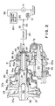
- FIG. 2 for a more detailed study of the driven pulley 37 of the variable diameter pulley system 3 and means associated therewith in accordance with the invention.
- the upper half of the driven pulley movable cone 37 b is shown displaced farthest away from the fixed cone 37 a
- the lower half of the movable cone shown positioned closest to the fixed cone, for the ease of understanding of the driven pulley operation.
- the movable cone 37 b of the driven pulley 37 has, rigidly mounted to its side away from the fixed cone 37 a , a shell 80 of substantially tubular shape concentrically surrounding the secondary shaft 35.
- a partition or partition element 39 a of similar shape but smaller size dividing the interior of the shell into a pulley actuation chamber 39 b contiguous to the driven pulley movable cone 37 b , and a counterbalance chamber 80 a opposite to the actuation chamber 39 b .
- the partition 39 a has a constricted end abutting a fixed collar 81 on the secondary shaft 35, and an enlarged end slidably but pressure-tightly held against the inside surface of the shell 80.
- the collar 81 serves the additional purpose of retaining the gear 43 a in place on the secondary shaft 35.
- the fluid in the counterbalance chamber 80 a serves to counterbalance the axial component of the centrifugal force of the fluid in the actuation chamber 39 b , particularly when the secondary shaft 35 is in rotation at high speed, holding the driven pulley movable cone 37 b in a desired axial position on the secondary shaft.
- the secondary shaft 35 has formed therein a mainline fluid passageway 82 and another fluid passageway 83, both passageways 82 and 83 extending axially of the secondary shaft.
- the mainline passageway 82 communicates with the actuation chamber 39 b for conveying mainline fluid pressure thereto.
- the pressure in the actuation chamber 39 b acts on the driven pulley movable cone 37 b , causing its axial displacement toward the driven pulley fixed cone 37 a .
- the other fluid passageway 83 in the secondary shaft 35 has one or more, (three in the illustrated embodiment), branch passageways 84 extending radially from its left hand end through the secondary shaft. These radial branch passageways 83 communicate with fluid outlets 81 a in the collar 81.
- the fluid outlets 81 a are open to the interior (counterbalance chamber 80 a ) or to the exterior of the enclosure 80 depending upon the axial position of the driven pulley movable cone 37 b on the secondary shaft 35.
- the position of the fluid outlets 81 a in the axial direction of the secondary shaft 35 constitutes an important feature of the invention, as described in more detail hereafter.
- a reference back to FIG. 2 will reveal that the right hand end of the fluid passageway 83 is open to the space 87 bounded by part of the clutch housing 6.
- the space 87 communicates, on one hand, with the interior of the main housing 7 via a passageway 86 in a clutch housing portion 6 a to which there is mounted a bearing 85 supporting the secondary shaft 35.
- the space 87 communicates with a source of lubrication pressure via a conduit 92 having a check valve 93 and cooler 94.
- the pressurized fluid from the pump 41 is fed through a conduit 88 to a pressure control valve 89.
- This valve drains part of the incoming pressurized fluid to provide a desired mainline pressure.
- the drain port of the pressure control valve 89 is communicated with the inlet side of the pump 41 via a drain line 90 having a pressure control valve 91 to provide a source of lubrication pressure, totally independent of mainline pressure, needed for the lubrication of the pulley belts and other moving parts of the transmission.
- This embodiment utilizes this lubrication pressure for introducing the fluid into the counterbalance chamber 80 a and, depending upon the axial position of the shell 80 on the secondary shaft 35, for lubricating some other parts of the transmission that will be set forth subsequently.
- drain line 90 communicates with the space 87 via the check valve 93 and cooler 94 to supply the fluid under lubrication pressure into the axial passageway 83 in the secondary shaft 35 and thence to the outlets 81 a via the radial passageways 84.
- FIG. 4 A consideration of FIG. 4 will show that, being coupled to the intermediate shaft 44 via the intermeshing gears 43 a and 43 b , the secondary shaft 35 of the pulley and belt drive system 3 is of necessity positioned above the level of the primary shaft 20.
- This relative placement of the primary and secondary shafts 20 and 35 gives rise to the possibility that the gears 43 a , 43 b , etc., may be poorly lubricated, particularly at low vehicle speed, because of insufficient splashing of oil by the final drive gear 46.
- the centrifugal force of the fluid in the actuation chamber 39 b is too negligible at low vehicle speed to justify counterbalancing it by the centrifugal force of the fluid in the counterbalance chamber 80 a .
- the noted fluid outlets 81 a have their position in the axial direction of the secondary shaft 35 determined in relation to the variable position of the shell 80 as hereinafter specified with reference to FIG. 3.
- the position of the fluid outlets 81 a is such that the constricted end 80 b , directed away from the driven pulley 37, of the shell 80 is positioned substantially opposite, or just on the pulley side of, the fluid outlets 81 a when the driven pulley 37 is conditioned for operation in the low speed range, preferably at the maximum speed ratio of the primary shaft 20 to the secondary shaft 35.
- the constricted end 80 b of the shell 80 has formed therein an annular taper 80 c which is directed away from the driven pulley 37. So tapered, the shell 80 provides a surface for directing the lubricating fluid toward the gear 43 a on the secondary shaft 35 when positioned as shown in FIG. 3.
- the mainline pressure from the pressure control valve 89 will be directed only into the actuation chamber 39 b of the driven pulley 37.
- the fluid pressure in the actuation chamber 39 b will act on the driven pulley movable cone 37 b , causing the same to move closest to the fixed cone 37 a , as represented by the bottom half of the movable cone in both FIGS. 1 and 2.
- the effective diameter of the driven pulley 37 is thus increased to a maximum.
- the effective diameter of the drive pulley 36 is at a minimum as its movable cone 36 b is positioned farthest away from its fixed cone 36 a , as represented by the top half of the drive pulley movable cone in FIG. 1.
- the infinitely variable speed drive system 3 is conditioned for operation in the low speed range, with the speed ratio of the pulleys 36 and 37 at the maximum.
- the mainline pressure will be fed into the actuation chamber 38 b of the drive pulley 36 thereby displacing its movable cone 36 b toward the fixed cone 36 a .
- the driven pulley movable cone 37 b will gradually travel away from the fixed cone 37 a .
- the pulleys 36 and 37 will be conditioned for overdrive as the drive pulley movable cone 36 b comes closest to the drive pulley fixed cone 36 a , as represented by the bottom half of the drive pulley movable cone in FIG. 1, whereas the driven pulley movable cone 37 b moves farthest away from the driven pulley fixed cone 37 a , as represented by its top half in FIGS. 1 and 2.
- the lubrication pressure will constantly develop on the drain line 90 of the pressure control valve 89 independently of the mainline pressure, it being understood that the pump 41 is driven from the vehicle engine. Cooled by the cooler 94, the lubricating fluid will flow into the axial passageway 83 in the secondary shaft 35 and, via the radial passageways 84 therein, will flow out of the fluid outlets 81 a in the collar 81.
- the fluid in the actuation chamber 39 b will centrifugally act on the driven pulley movable cone 37 b , tending to displace the same toward the driven pulley fixed cone 37 a , the partition 39 a being locked against axial displacement of the driven pulley movable cone 37 b in the direction away from the driven pulley 37.
- the centrifugal force of the fluid in the counterbalance chamber 80 a of increased capacity will act on the shell 80 of stepped tubular shape, causing the same to exert a pull on the driven pulley movable cone 37 b .
- the centrifugal force of the fluid in the counterbalance chamber 80 a therefore counteracts that of the fluid in the actuation chamber 39 b .
- the constricted end 80 b of the shell 80 will nearly discommunicate the counterbalance chamber 80 a from the fluid outlets 81 a in the collar 81.
- the lubricating fluid will then be hardly admitted into the counterbalance chamber 80 a ; instead, guided by the taper 80 c in the enclosure 80, the lubricating fluid will be directed away from the driven pulley 37 for lubricating the reduction gears 43 a and 43 b , bearing 85, etc., which are located above the level of the primary shaft 20.
- the fundamental concepts of the invention may be applied not only to the driven pulley but also to the drive pulley of the variable diameter pulley system.
- the pulley system is herein shown incorporated in a transmission with an electromagnetic powder clutch, it lends itself to use with hydraulic torque converters, mechanical clutches, etc.
Landscapes
- Engineering & Computer Science (AREA)
- General Engineering & Computer Science (AREA)
- Mechanical Engineering (AREA)
- Transmissions By Endless Flexible Members (AREA)
Claims (3)
- Variateur continu de vitesse, comprenant une poulie d'entraînement (36) de diamètre variable et prévue sur un arbre primaire (20), une poulie entraînée (37) de diamètre variable et prévue sur un arbre secondaire (35), une courroie sans fin (34) passant autour de la poulie d'entraînement et de la poulie entraînée afin de transmettre la rotation de l'arbre primaire à l'arbre secondaire suivant un rapport variable de vitesses dépendant des diamètres effectifs relatifs de la poulie d'entraînement et de la poulie entraînée, variateur dans lequel la poulie entraînée comporte un cône fixe (37a) monté de manière fixe sur l'arbre secondaire, et un cône mobile (37b) monté sur l'arbre secondaire en vue d'une rotation conjointe avec ce dernier et pour un déplacement axial relatif par rapport à l'arbre secondaire vers et à l'écart du cône fixe, variateur dans lequel une carcasse essentiellement tubulaire (80), entourant coaxialement l'arbre secondaire, présente une extrémité agrandie rigidement fixée au cône mobile de la poulie entraînée, et une extrémité restreinte (80b) montée de manière libre sur l'arbre secondaire, variateur dans lequel également l'intérieur de la carcasse est subdivisé par un élément de cloisonnement (39a) en une chambre d'actionnement (39b) et une chambre d'équilibrage (80a), la chambre d'actionnement étant alimentée par un fluide sous pression pour assurer un déplacement réglable du cône mobile, en même temps que de la carcasse qui y est attachée, et ce vers et à l'écart du cône fixe, caractérisé en ce que l'arbre secondaire (35) comporte un passage de fluide (83, 84) qui y est formé avec une sortie de fluide (81a) prévue dans une position axiale telle, sur l'arbre secondaire, que l'extrémité restreinte (80b) de la carcasse (80) est disposée sensiblement à l'opposé de la sortie de fluide, à un rapport élevé prévu de vitesses de l'arbre primaire (20) par rapport à l'arbre secondaire (35), afin de diriger le fluide sortant sous pression de la sortie de fluide vers l'extérieur de la carcasse, et en ce que l'extrémité restreinte de la carcasse admet le fluide sous pression venant de la sortie de fluide (81a) vers et dans la chambre d'équilibrage (80a) afin de contrebalancer la force centrifuge du fluide dans la chambre d'actionnement (39b) lorsque le cône mobile (37b) de la poulie entraînée (37) se déplace à l'écart du cône fixe (37a) pour rendre la vitesse de rotation de l'arbre secondaire supérieure à celle existant au rapport élevé prévu de vitesses.
- Variateur continu de vitesse suivant la revendication 1, caractérisé en ce que l'extrémité restreinte (80b) de la carcasse (80) est conformée pour présenter une surface (80c) destinée à diriger le fluide sous pression venant de la sortie de fluide (81a) dans un sens s'écartant de la poulie entraînée (37).
- Variateur continu de vitesse suivant la revendication 1, dans lequel la chambre d'actionnement (39b) est alimentée par le fluide sous pression venant d'une source (89) de pression de la canalisation principale, caractérisé en ce que la chambre d'équilibrage (80a) est alimentée par le fluide sous pression venant d'une source (90, 91) de pression de lubrification.
Applications Claiming Priority (2)
| Application Number | Priority Date | Filing Date | Title |
|---|---|---|---|
| JP328273/87 | 1987-12-23 | ||
| JP62328273A JP2662961B2 (ja) | 1987-12-23 | 1987-12-23 | 無段変速機のプーリ |
Publications (2)
| Publication Number | Publication Date |
|---|---|
| EP0321921A1 EP0321921A1 (fr) | 1989-06-28 |
| EP0321921B1 true EP0321921B1 (fr) | 1992-04-29 |
Family
ID=18208380
Family Applications (1)
| Application Number | Title | Priority Date | Filing Date |
|---|---|---|---|
| EP88121286A Expired - Lifetime EP0321921B1 (fr) | 1987-12-23 | 1988-12-20 | Variateur continu de vitesse avec dispositif de poulie à diamètre variable |
Country Status (4)
| Country | Link |
|---|---|
| US (1) | US4850938A (fr) |
| EP (1) | EP0321921B1 (fr) |
| JP (1) | JP2662961B2 (fr) |
| DE (1) | DE3870597D1 (fr) |
Families Citing this family (17)
| Publication number | Priority date | Publication date | Assignee | Title |
|---|---|---|---|---|
| JPH0243722U (fr) * | 1988-09-21 | 1990-03-26 | ||
| JPH02154848A (ja) * | 1988-12-05 | 1990-06-14 | Aisin Aw Co Ltd | ベルト式無段変速装置 |
| JPH0434548U (fr) * | 1990-07-19 | 1992-03-23 | ||
| US5269726A (en) * | 1991-06-26 | 1993-12-14 | Borg-Warner Automotive, Inc. | Control system and strategies for a double acting secondary sheave servo for a continuously variable transmission |
| BE1008462A3 (nl) * | 1994-06-21 | 1996-05-07 | Vcst Nv | Werkwijze voor het smeren en/of koelen van een transmissie-eenheid bij motorvoertuigen en transmissie-eenheid die deze werkwijze toepast. |
| NL1001756C2 (nl) * | 1995-11-28 | 1997-05-30 | Doornes Transmissie Bv | Poelie. |
| BE1010369A3 (nl) * | 1996-06-18 | 1998-07-07 | Vcst Nv | Transmissie-eenheid voor motorvoertuigen. |
| JP2002295613A (ja) * | 2001-03-30 | 2002-10-09 | Honda Motor Co Ltd | ベルト式無段変速機 |
| EP1271002B1 (fr) * | 2001-06-18 | 2004-10-13 | Van Doorne's Transmissie B.V. | Transmission à variation continue et poulie |
| US6790108B1 (en) * | 2003-02-12 | 2004-09-14 | Dan Schiebout | Boat propulsion system |
| JP2008057614A (ja) * | 2006-08-30 | 2008-03-13 | Yamaha Motor Co Ltd | ベルト式無段階変速装置 |
| JP4963901B2 (ja) * | 2006-08-30 | 2012-06-27 | ヤマハ発動機株式会社 | ベルト式無段階変速装置 |
| US7845452B2 (en) * | 2007-05-16 | 2010-12-07 | Polaris Industries Inc. | Drivetrain for an all terrain vehicle |
| USD595188S1 (en) | 2008-04-03 | 2009-06-30 | Polaris Industries Inc. | All terrain vehicle |
| US8596398B2 (en) * | 2007-05-16 | 2013-12-03 | Polaris Industries Inc. | All terrain vehicle |
| US20090195035A1 (en) | 2008-02-04 | 2009-08-06 | Polaris Industries Inc. | ATV having arrangement for a passenger |
| JP7444151B2 (ja) * | 2021-09-28 | 2024-03-06 | 株式会社アイシン | 車両用駆動装置 |
Family Cites Families (8)
| Publication number | Priority date | Publication date | Assignee | Title |
|---|---|---|---|---|
| FR1367619A (fr) * | 1963-06-10 | 1964-07-24 | Cazeneuve Sa | Perfectionnements aux poulies à joues mobiles commandées hydrauliquement dans les changements de vitesses progressifs à courroies |
| FR2192671A5 (fr) * | 1972-07-11 | 1974-02-08 | Piv Antrieb Reimers Kg Werner | |
| DE2846580C2 (de) * | 1978-10-26 | 1982-12-09 | P.I.V. Antrieb Werner Reimers GmbH & Co KG, 6380 Bad Homburg | Stufenlos einstellbares Kegelscheibengetriebe |
| JPS57137757A (en) * | 1981-02-16 | 1982-08-25 | Aisin Warner Ltd | Controller for fluid pressure of belt type stepless change gear |
| JPS57171154A (en) * | 1981-04-11 | 1982-10-21 | Nissan Motor Co Ltd | V-belt type stepless speed changer |
| JPS60155153A (ja) * | 1983-12-17 | 1985-08-15 | Toyo Soda Mfg Co Ltd | チオカ−バメ−ト誘導体 |
| US4552545A (en) * | 1984-06-18 | 1985-11-12 | General Motors Corporation | Centrifugal pressure compensator for a variable drive pulley |
| US4717368A (en) * | 1986-01-23 | 1988-01-05 | Aisin-Warner Kabushiki Kaisha | Stepless belt transmission |
-
1987
- 1987-12-23 JP JP62328273A patent/JP2662961B2/ja not_active Expired - Lifetime
-
1988
- 1988-12-13 US US07/284,308 patent/US4850938A/en not_active Expired - Lifetime
- 1988-12-20 DE DE8888121286T patent/DE3870597D1/de not_active Expired - Lifetime
- 1988-12-20 EP EP88121286A patent/EP0321921B1/fr not_active Expired - Lifetime
Also Published As
| Publication number | Publication date |
|---|---|
| JPH01169165A (ja) | 1989-07-04 |
| US4850938A (en) | 1989-07-25 |
| DE3870597D1 (de) | 1992-06-04 |
| JP2662961B2 (ja) | 1997-10-15 |
| EP0321921A1 (fr) | 1989-06-28 |
Similar Documents
| Publication | Publication Date | Title |
|---|---|---|
| EP0321921B1 (fr) | Variateur continu de vitesse avec dispositif de poulie à diamètre variable | |
| US4461188A (en) | Dual clutch multiple countershaft transmission | |
| US4467670A (en) | Belt drive continuously-variable speed automatic transmission | |
| EP0943841B1 (fr) | Traction toutes roues motrices avec double mode de fonctionnement et variateur continu de vitesse | |
| CA1138677A (fr) | Chaine cinematique a transmission continuellement variable pour vehicule automobile | |
| US8261883B2 (en) | Vehicle power transmission device | |
| US4706518A (en) | Automatic transmission having C.V.T. system for a vehicle | |
| EP0483764A1 (fr) | Transmission continue à courroie | |
| US4467669A (en) | Working fluid distributing system for a belt drive continuously-variable speed automatic transmission | |
| EP0168940B1 (fr) | Appareil hydraulique de contrôle pour transmission commandée hydrauliquement et comportant un variateur continu | |
| US4549447A (en) | Belt drive continuously-variable speed automatic transmission | |
| US4459872A (en) | Clutch actuator | |
| US4649763A (en) | Multiple-speed, hydrokinetic transmission | |
| US4484493A (en) | Cone pulley V-belt continuously variable transmission | |
| US4898050A (en) | System for controlling the pressure of oil for a continuously variable transmission | |
| US5480361A (en) | Change direction planetary gearing for continuously variable transmission | |
| EP0321621B1 (fr) | Transmission continue de vitesse pour véhicules automobiles | |
| US6007448A (en) | Lubrication structure for planetary gear assembly | |
| EP0147153B1 (fr) | Système de détection du rapport de transmission dans un variateur continu de vitesse avec un moyen de lubrification | |
| EP0999381B1 (fr) | Dispositif de transmission pour véhicules | |
| EP0943840B1 (fr) | Traction toutes roues motrices avec double mode de fonctionnement et variateur continu de vitesse | |
| US4529393A (en) | Infinitely variable belt-drive transmission | |
| WO1985002663A1 (fr) | Transmission variable en continu a deux plages | |
| KR100460903B1 (ko) | 차량용 무단 변속기 | |
| JP3366713B2 (ja) | 自動変速機の潤滑装置 |
Legal Events
| Date | Code | Title | Description |
|---|---|---|---|
| PUAI | Public reference made under article 153(3) epc to a published international application that has entered the european phase |
Free format text: ORIGINAL CODE: 0009012 |
|
| 17P | Request for examination filed |
Effective date: 19890206 |
|
| AK | Designated contracting states |
Kind code of ref document: A1 Designated state(s): DE GB IT NL |
|
| 17Q | First examination report despatched |
Effective date: 19910729 |
|
| GRAA | (expected) grant |
Free format text: ORIGINAL CODE: 0009210 |
|
| AK | Designated contracting states |
Kind code of ref document: B1 Designated state(s): DE GB IT NL |
|
| PG25 | Lapsed in a contracting state [announced via postgrant information from national office to epo] |
Ref country code: IT Free format text: LAPSE BECAUSE OF FAILURE TO SUBMIT A TRANSLATION OF THE DESCRIPTION OR TO PAY THE FEE WITHIN THE PRE;WARNING: LAPSES OF ITALIAN PATENTS WITH EFFECTIVE DATE BEFORE 2007 MAY HAVE OCCURRED AT ANY TIME BEFORE 2007. THE CORRECT EFFECTIVE DATE MAY BE DIFFERENT FROM THE ONE RECORDED.SCRIBED TIME-LIMIT Effective date: 19920429 Ref country code: NL Effective date: 19920429 |
|
| REF | Corresponds to: |
Ref document number: 3870597 Country of ref document: DE Date of ref document: 19920604 |
|
| NLV1 | Nl: lapsed or annulled due to failure to fulfill the requirements of art. 29p and 29m of the patents act | ||
| PLBE | No opposition filed within time limit |
Free format text: ORIGINAL CODE: 0009261 |
|
| STAA | Information on the status of an ep patent application or granted ep patent |
Free format text: STATUS: NO OPPOSITION FILED WITHIN TIME LIMIT |
|
| 26N | No opposition filed | ||
| REG | Reference to a national code |
Ref country code: GB Ref legal event code: 746 Effective date: 19981027 |
|
| PGFP | Annual fee paid to national office [announced via postgrant information from national office to epo] |
Ref country code: GB Payment date: 19981224 Year of fee payment: 11 |
|
| PGFP | Annual fee paid to national office [announced via postgrant information from national office to epo] |
Ref country code: DE Payment date: 19981229 Year of fee payment: 11 |
|
| PG25 | Lapsed in a contracting state [announced via postgrant information from national office to epo] |
Ref country code: GB Free format text: LAPSE BECAUSE OF NON-PAYMENT OF DUE FEES Effective date: 19991220 |
|
| GBPC | Gb: european patent ceased through non-payment of renewal fee |
Effective date: 19991220 |
|
| PG25 | Lapsed in a contracting state [announced via postgrant information from national office to epo] |
Ref country code: DE Free format text: LAPSE BECAUSE OF NON-PAYMENT OF DUE FEES Effective date: 20001003 |