EP0321987A2 - Eisenbahnbremsregelsystem - Google Patents
Eisenbahnbremsregelsystem Download PDFInfo
- Publication number
- EP0321987A2 EP0321987A2 EP88121533A EP88121533A EP0321987A2 EP 0321987 A2 EP0321987 A2 EP 0321987A2 EP 88121533 A EP88121533 A EP 88121533A EP 88121533 A EP88121533 A EP 88121533A EP 0321987 A2 EP0321987 A2 EP 0321987A2
- Authority
- EP
- European Patent Office
- Prior art keywords
- generating
- fact
- train
- signal
- selector
- Prior art date
- Legal status (The legal status is an assumption and is not a legal conclusion. Google has not performed a legal analysis and makes no representation as to the accuracy of the status listed.)
- Granted
Links
- 230000005520 electrodynamics Effects 0.000 claims abstract description 37
- 230000005284 excitation Effects 0.000 claims abstract description 7
- 230000003137 locomotive effect Effects 0.000 claims description 13
- 230000001276 controlling effect Effects 0.000 claims description 8
- 230000003750 conditioning effect Effects 0.000 claims description 3
- 230000001143 conditioned effect Effects 0.000 claims description 2
- 230000002596 correlated effect Effects 0.000 claims 1
- 239000012530 fluid Substances 0.000 abstract 1
- 230000003247 decreasing effect Effects 0.000 description 3
- 230000001105 regulatory effect Effects 0.000 description 3
- 206010001497 Agitation Diseases 0.000 description 2
- 238000010586 diagram Methods 0.000 description 2
- 230000015556 catabolic process Effects 0.000 description 1
Images


Classifications
-
- B—PERFORMING OPERATIONS; TRANSPORTING
- B60—VEHICLES IN GENERAL
- B60L—PROPULSION OF ELECTRICALLY-PROPELLED VEHICLES; SUPPLYING ELECTRIC POWER FOR AUXILIARY EQUIPMENT OF ELECTRICALLY-PROPELLED VEHICLES; ELECTRODYNAMIC BRAKE SYSTEMS FOR VEHICLES IN GENERAL; MAGNETIC SUSPENSION OR LEVITATION FOR VEHICLES; MONITORING OPERATING VARIABLES OF ELECTRICALLY-PROPELLED VEHICLES; ELECTRIC SAFETY DEVICES FOR ELECTRICALLY-PROPELLED VEHICLES
- B60L7/00—Electrodynamic brake systems for vehicles in general
- B60L7/24—Electrodynamic brake systems for vehicles in general with additional mechanical or electromagnetic braking
-
- B—PERFORMING OPERATIONS; TRANSPORTING
- B60—VEHICLES IN GENERAL
- B60T—VEHICLE BRAKE CONTROL SYSTEMS OR PARTS THEREOF; BRAKE CONTROL SYSTEMS OR PARTS THEREOF, IN GENERAL; ARRANGEMENT OF BRAKING ELEMENTS ON VEHICLES IN GENERAL; PORTABLE DEVICES FOR PREVENTING UNWANTED MOVEMENT OF VEHICLES; VEHICLE MODIFICATIONS TO FACILITATE COOLING OF BRAKES
- B60T13/00—Transmitting braking action from initiating means to ultimate brake actuator with power assistance or drive; Brake systems incorporating such transmitting means, e.g. air-pressure brake systems
- B60T13/10—Transmitting braking action from initiating means to ultimate brake actuator with power assistance or drive; Brake systems incorporating such transmitting means, e.g. air-pressure brake systems with fluid assistance, drive, or release
- B60T13/66—Electrical control in fluid-pressure brake systems
- B60T13/665—Electrical control in fluid-pressure brake systems the systems being specially adapted for transferring two or more command signals, e.g. railway systems
-
- B—PERFORMING OPERATIONS; TRANSPORTING
- B60—VEHICLES IN GENERAL
- B60T—VEHICLE BRAKE CONTROL SYSTEMS OR PARTS THEREOF; BRAKE CONTROL SYSTEMS OR PARTS THEREOF, IN GENERAL; ARRANGEMENT OF BRAKING ELEMENTS ON VEHICLES IN GENERAL; PORTABLE DEVICES FOR PREVENTING UNWANTED MOVEMENT OF VEHICLES; VEHICLE MODIFICATIONS TO FACILITATE COOLING OF BRAKES
- B60T15/00—Construction arrangement, or operation of valves incorporated in power brake systems and not covered by groups B60T11/00 or B60T13/00
- B60T15/02—Application and release valves
- B60T15/04—Driver's valves
- B60T15/14—Driver's valves influencing electric control means
-
- B—PERFORMING OPERATIONS; TRANSPORTING
- B60—VEHICLES IN GENERAL
- B60L—PROPULSION OF ELECTRICALLY-PROPELLED VEHICLES; SUPPLYING ELECTRIC POWER FOR AUXILIARY EQUIPMENT OF ELECTRICALLY-PROPELLED VEHICLES; ELECTRODYNAMIC BRAKE SYSTEMS FOR VEHICLES IN GENERAL; MAGNETIC SUSPENSION OR LEVITATION FOR VEHICLES; MONITORING OPERATING VARIABLES OF ELECTRICALLY-PROPELLED VEHICLES; ELECTRIC SAFETY DEVICES FOR ELECTRICALLY-PROPELLED VEHICLES
- B60L2200/00—Type of vehicles
- B60L2200/26—Rail vehicles
Definitions
- the electrodynamic type is operated by supplying the electric motors (usually two) on the locomotive with a given armature current for producing a brake torque on the motors.
- the pneumatic or electropneumatic type is operated by regulating the air pressure in the main brake line, for producing a given pressure in the brake control cylinders.
- Known brake control setups usually feature an operating mode selector (overload, run, slow brake, fast brake, etc.) and an automatic regulating device for controlling air supply and exhaust on the main line according to the selector setting.
- Said automatic regulating device comprises a relay valve; a pair of electrovalves for supplying and exhausting a control chamber on the relay valve; a pair of pressure transducers for generating electric signals proportional to the air pressure inside the relay valve control chamber and main line respectively; and an electronic processing unit for controlling excitation of the electrovalves on the basis of both the selector setting and the electric signals generated by the pressure transducers.
- the aim of the present invention is to provide a railroad train brake control system designed to overcome the aforementioned drawback typically associated with known systems, and which also provides for a high degree or reliability and safety.
- a railroad train brake control system said train presenting at least one electric locomotive and a number of cars, and said system comprising: an air supply line; a main air line; a system operating mode selector (overload, run, slow brake, fast brake, etc.); a relay valve between said air supply line and said main air line; a pair of electrovalves for respectively supplying and exhausting a relay valve control chamber; a pair of pressure transducers for generating electric signals proportional to the air pressure in the main air line and relay valve control chamber respectively; characterised by the fact that it comprises: first means for generating an electric signal depending on the electrodynamic braking efficiency of said electric locomotive; second means for generating an electric signal depending on the traveling speed of said train; and an electronic processing unit for controlling excitation of said electrovalves and electrodynamic braking of said train on the basis of both the setting of said selector and said electric signals supplied by said transducers and said first and said second generating means.
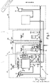
- Number 1 in Fig.1 indicates a railraod train convenient strictlyly consisting of a front electric locomotive 21, a rear electric locomotive 22, and a number of cars 23 (23a, 23b, ... 23n).
- Train 1 features a brake control system 2 in accordance with the present invention, and housed predominantly in the drive cabs of locomotives 21 and 22, and partly inside cars 23.
- System 2 substantially comprises: an air supply line 15 for supplying compressed air from a tank (not shown); a main air line 16 connected to a known type of distributor (not shown) controlling the brake cylinders; a selector 13 having a number of system 2 operating mode settings (isolate, overload, run, slow brake, fast brake, etc.), each corresponding to an electric reference signal generated, for example, by a potentiometer 14 assigned to selector 13; a relay valve 8 between air supply line 15 and main line 16; a pair of electrovalves 3 and 4 for respectively supplying and exhausting a relay valve 8 control chamber (not shown); a pair of pressure transducers 9 and 10 for generating electric signals proportional to the air pressure inside main line 16 and said relay valve 8 control chamber respectively; an electronic processing unit 11 for controlling excitation of electrovalves 3 and 4 controlling supply and exhaust of main line 16, on the basis of both the selector 13 setting and the electric signals generated by transducers 9 and 10.
- Processing unit 11 presents nine inputs 31-39 and six outputs 41-46.
- Inputs 31, 32 and 33 are connected respectively to the cursor of potentiometer 14 and to transducers 9 and 10.
- Inputs 34 and 35 are connected to respective blocks 24 and 25 for generating electric signals depending on the electrodynamic braking efficiency and traveling speed of train 1.
- Input 36 is connected to a transducer 26a for indicating the setting of an electrovalve 30a installed in car 23a.
- Input 37 is connected to a series of alarm contacts 27a, ... 27n installed in respective cars 23a, ... 23n.
- Inputs 38 and 39 are connected to known circuits (not shown) for supplying unit 11 with predetermined brake control signals under specific operating conditions.
- Outputs 41 and 42 are connected respectively to electrovalves 3 and 4; and outputs 43 and 44 to respective electrovalves 3a and 4a in car 23a, for supplying or exhausting compressed air from main line 16.
- Output 45 is connected to an electrovalve 30a series-connected to an emergency exhaust member 28a passenger-operated simultaneously to contact 27a, said electrovalve 30a being designed to intercept exhaust of main line 16 as described hereinafter.
- Output 46 is connected to an appropriate electrodynamic brake control device 47.
- Potentiometer 14 substantially consists of a voltage divider consisting of a central potentiometric portion 50 with a cursor, a pair of fixed positive pole resistors 51, 52, and a pair of fixed ground resistors 53, 54, so as to produce gradually decreasing voltage pickup points 55, 56, 57, 58, 59, 60.
- the cursor on portion 50 is connected to a switch terminal on switch 61, the other switch terminal being connected to pickup point 59.
- Switch 61 is controlled by an SR flip-flop 62 having the S input connected to terminal 37, and the R input to a reset network installed in the drive cab of train 1 and consisting of a positive-pole-connected push-button 63 and a grounded resistor 64.
- amplifier 82 consists of two amplifying units having respective cascade-connected amplifiers 101, 102, each with an input resistor 103, 104 and an input-output connecting network 105, 106 consisting of a number of parallel branches, each having a resistor and a series-connected switch controlled by generator 24 or 25.
- Network 105 presents four branches with four resistors 107, 108, 109, 110 series-connected to four switches 111, 112, 113, 114, each having a control input connected to a respective output of generator 24.
- switches 111, 112, 113, 114 are closed when the number of motors capable of braking electrodynamically is 4, 3, 2 and 1 respectively.
- the output of flip-flop 126 is connected to one input of a two-input NAND circuit 129, the other input of which is connected to the output of a voltage comparator 130 having its inverting input connected to terminal 33 and its non-inverting input 131 connected to a terminal supplying a reference voltage signal (Vr) as described in more detail later on.
- Vr reference voltage signal
- NAND circuit 129 The output of NAND circuit 129 is connected to electrovalve 30a (via NOT circuit 136), and to a delay network 132 consisting of resistor 133 and condenser 134.
- the output of network 132 and the terminal connecting position transducer 26a are connected to respective inputs of NOR circuit 135, the output of which is connected to terminal 36.
- the signal picked up at point 55 is supplied to compara tors 75 and 79, which immediately disable electrovalve 4 and enable electrovalve 3 via NOR circuit 93 and electrovalves 3a, ... 3n via flip-flip 83.
- Electrovalve 3 supplies the control chamber of relay valve 8, which, in turn, raises the pressure on main line 16. Once the required pressure is reached in the chamber of relay valve 8 and main line 16, signals are generated by respective transducers 10 and 9 for disabling excitation of electrovalve 3 and electrovalves 3a,...3n via comparator 78 and flip-flop 83.
- potentiometer 14 The signal picked up at point 55 by potentiometer 14 is actually added to a ramp signal generated by an appropriate circuit (not shown) which, being of known performance, is not described herein for the sake of simplicity.
- potentiometer 14 is set to pickup point 56, thus producing a slightly lower voltage level and, consequently, a lower pressure (e.g. 5 bar) in main line 16.
- subtracter circuit 99 supplies an output signal equal to the difference between the previous signal and the contribution of said positive signal amplified on the basis of electrodynamic braking efficiency and the traveling speed of train 1, as already stated.
- the 0 signal at the output of network 68 also zeroes the output of AND circuit 90, which, via NOT circuit 91, activates switch 88, thus producing a maximum control signal on device 47 and, consequently, maximum electro-dynamic braking force. Moreover, the 0 signal at the output of AND circuit 90 switches the output of NAND circuit 92 to 1, thus energizing electrovalve 4 and also electrovalves 4a,...4n via flip-flop 84.
- Flip-flop 62 immediately activates switch 61 for achieving maximum service braking as already described; which condition may be reset by the crew simply pressing button 63, for preventing the train from being stopped on viaducts or inside tunnels, etc.
Landscapes
- Engineering & Computer Science (AREA)
- Transportation (AREA)
- Mechanical Engineering (AREA)
- Physics & Mathematics (AREA)
- Electromagnetism (AREA)
- Power Engineering (AREA)
- Braking Systems And Boosters (AREA)
- Electric Propulsion And Braking For Vehicles (AREA)
- Train Traffic Observation, Control, And Security (AREA)
Applications Claiming Priority (2)
| Application Number | Priority Date | Filing Date | Title |
|---|---|---|---|
| IT8768118A IT1211623B (it) | 1987-12-23 | 1987-12-23 | Sistema di comando e di controllodella frenatura di un convoglio ferroviario |
| IT6811887 | 1987-12-23 |
Publications (3)
| Publication Number | Publication Date |
|---|---|
| EP0321987A2 true EP0321987A2 (de) | 1989-06-28 |
| EP0321987A3 EP0321987A3 (en) | 1990-12-19 |
| EP0321987B1 EP0321987B1 (de) | 1995-03-15 |
Family
ID=11307976
Family Applications (1)
| Application Number | Title | Priority Date | Filing Date |
|---|---|---|---|
| EP88121533A Expired - Lifetime EP0321987B1 (de) | 1987-12-23 | 1988-12-22 | Eisenbahnbremsregelsystem |
Country Status (6)
| Country | Link |
|---|---|
| EP (1) | EP0321987B1 (de) |
| AT (1) | ATE119835T1 (de) |
| DE (1) | DE3853350T2 (de) |
| ES (1) | ES2072259T3 (de) |
| IT (1) | IT1211623B (de) |
| PT (1) | PT89334B (de) |
Cited By (3)
| Publication number | Priority date | Publication date | Assignee | Title |
|---|---|---|---|---|
| WO2003086809A1 (de) * | 2002-04-18 | 2003-10-23 | Siemens Aktiengesellschaft | Verfahren zum elektrodynamischen bremsen eines schienenfahrzeugs |
| FR3064965A1 (fr) * | 2017-04-10 | 2018-10-12 | Matisa Materiel Industriel S.A. | Robinet de mecanicien simplifie et circuit pneumatique de freinage d’une rame ferroviaire incorporant un tel robinet de mecanicien |
| CN115214583A (zh) * | 2022-07-26 | 2022-10-21 | 眉山中车制动科技股份有限公司 | 一种铁路货车电空制动阀的控制系统 |
Family Cites Families (2)
| Publication number | Priority date | Publication date | Assignee | Title |
|---|---|---|---|---|
| US3528709A (en) * | 1968-09-23 | 1970-09-15 | Gen Signal Corp | Electric current-to-pneumatic pressure transducer |
| US4225813A (en) * | 1978-11-28 | 1980-09-30 | Westinghouse Electric Corp. | Transit vehicle dynamic brake control apparatus |
-
1987
- 1987-12-23 IT IT8768118A patent/IT1211623B/it active
-
1988
- 1988-12-22 DE DE3853350T patent/DE3853350T2/de not_active Expired - Fee Related
- 1988-12-22 EP EP88121533A patent/EP0321987B1/de not_active Expired - Lifetime
- 1988-12-22 AT AT88121533T patent/ATE119835T1/de not_active IP Right Cessation
- 1988-12-22 ES ES88121533T patent/ES2072259T3/es not_active Expired - Lifetime
- 1988-12-23 PT PT89334A patent/PT89334B/pt not_active IP Right Cessation
Cited By (8)
| Publication number | Priority date | Publication date | Assignee | Title |
|---|---|---|---|---|
| WO2003086809A1 (de) * | 2002-04-18 | 2003-10-23 | Siemens Aktiengesellschaft | Verfahren zum elektrodynamischen bremsen eines schienenfahrzeugs |
| AU2003229274B2 (en) * | 2002-04-18 | 2008-05-15 | Siemens Mobility GmbH | Method for electrodynamically braking a rail vehicle |
| CN100420585C (zh) * | 2002-04-18 | 2008-09-24 | 西门子公司 | 用于轨道车辆的电动力制动的方法 |
| US7533943B2 (en) | 2002-04-18 | 2009-05-19 | Siemens Aktiengesellschaft | Method for electrodynamically braking a rail vehicle |
| FR3064965A1 (fr) * | 2017-04-10 | 2018-10-12 | Matisa Materiel Industriel S.A. | Robinet de mecanicien simplifie et circuit pneumatique de freinage d’une rame ferroviaire incorporant un tel robinet de mecanicien |
| WO2018189115A1 (fr) * | 2017-04-10 | 2018-10-18 | Matisa Materiel Industriel S.A. | Robinet de mécanicien simplifié et circuit pneumatique de freinage d'une rame ferroviaire incorporant un tel robinet de mécanicien |
| CN115214583A (zh) * | 2022-07-26 | 2022-10-21 | 眉山中车制动科技股份有限公司 | 一种铁路货车电空制动阀的控制系统 |
| CN115214583B (zh) * | 2022-07-26 | 2023-09-22 | 眉山中车制动科技股份有限公司 | 一种铁路货车电空制动阀的控制系统 |
Also Published As
| Publication number | Publication date |
|---|---|
| DE3853350D1 (de) | 1995-04-20 |
| ES2072259T3 (es) | 1995-07-16 |
| ATE119835T1 (de) | 1995-04-15 |
| DE3853350T2 (de) | 1996-01-04 |
| EP0321987A3 (en) | 1990-12-19 |
| PT89334B (pt) | 1993-12-31 |
| EP0321987B1 (de) | 1995-03-15 |
| PT89334A (pt) | 1989-09-14 |
| IT8768118A0 (it) | 1987-12-23 |
| IT1211623B (it) | 1989-11-03 |
Similar Documents
| Publication | Publication Date | Title |
|---|---|---|
| JP7138656B2 (ja) | 鉄道車両の緊急ブレーキおよびサービスブレーキの電子制御システム | |
| US8774990B2 (en) | Method for demanding safety reactions for a rail vehicle | |
| US3920280A (en) | Antiskid brake control system having malfunction protection | |
| US3799623A (en) | Controlling railway vehicle brakes | |
| KR102622589B1 (ko) | 철도 차량의 전자식 제동 제어 시스템 | |
| US4316640A (en) | Electro pneumatic brake system for railway car | |
| JPH10203346A (ja) | 汎用空気ブレーキ制御ユニット | |
| KR20220170460A (ko) | 차량용 제동장치 | |
| GB2158901A (en) | Brake system for automotive vehicles | |
| US4494199A (en) | Brake system, especially for a motor vehicle | |
| EP0321987B1 (de) | Eisenbahnbremsregelsystem | |
| US3901558A (en) | Pneumatic/electro-pneumatic interlock circuitry for double-end control locomotive | |
| JP2022541595A (ja) | 少なくとも1つの鉄道車両のための電空非常ブレーキおよび電空常用ブレーキの制御システム | |
| GB2162265A (en) | Braking pressure generator for slip-controlled brake systems | |
| US2719911A (en) | Train speed control system | |
| EP1316489B1 (de) | Sicherheitssystem zum kontinuierlichen Kontrollieren der Integrität eines Schienenfahrzeuges | |
| US11904827B2 (en) | Rotational monitoring system of at least one axle for a railway vehicle or train | |
| EP0335532B1 (de) | Elektropneumatisches Bremssystem | |
| US4165136A (en) | Control system of a railway vehicle air braking system | |
| JPH0884402A (ja) | 鉄道車両用ブレーキ監視装置 | |
| CN119013175A (zh) | 用于轨道车辆的制动系统和制动方法 | |
| CN119013180A (zh) | 用于轨道车辆的制动系统和制动方法 | |
| US6474149B1 (en) | Method and apparatus for detecting a defective pressure switch | |
| US2656222A (en) | Combined pneumatic and dynamic brake apparatus | |
| US2402403A (en) | Electric decelerometer |
Legal Events
| Date | Code | Title | Description |
|---|---|---|---|
| PUAI | Public reference made under article 153(3) epc to a published international application that has entered the european phase |
Free format text: ORIGINAL CODE: 0009012 |
|
| AK | Designated contracting states |
Kind code of ref document: A2 Designated state(s): AT BE CH DE ES FR GB LI |
|
| PUAL | Search report despatched |
Free format text: ORIGINAL CODE: 0009013 |
|
| AK | Designated contracting states |
Kind code of ref document: A3 Designated state(s): AT BE CH DE ES FR GB LI |
|
| 17P | Request for examination filed |
Effective date: 19910522 |
|
| 17Q | First examination report despatched |
Effective date: 19921209 |
|
| GRAA | (expected) grant |
Free format text: ORIGINAL CODE: 0009210 |
|
| AK | Designated contracting states |
Kind code of ref document: B1 Designated state(s): AT BE CH DE ES FR GB LI |
|
| REF | Corresponds to: |
Ref document number: 119835 Country of ref document: AT Date of ref document: 19950415 Kind code of ref document: T |
|
| REF | Corresponds to: |
Ref document number: 3853350 Country of ref document: DE Date of ref document: 19950420 |
|
| REG | Reference to a national code |
Ref country code: CH Ref legal event code: PFA Free format text: SAB WABCO S.P.A. |
|
| ET | Fr: translation filed | ||
| RAP4 | Party data changed (patent owner data changed or rights of a patent transferred) |
Owner name: SAB WABCO S.P.A. |
|
| REG | Reference to a national code |
Ref country code: ES Ref legal event code: FG2A Ref document number: 2072259 Country of ref document: ES Kind code of ref document: T3 |
|
| REG | Reference to a national code |
Ref country code: FR Ref legal event code: CD |
|
| PG25 | Lapsed in a contracting state [announced via postgrant information from national office to epo] |
Ref country code: AT Effective date: 19951222 |
|
| BECN | Be: change of holder's name |
Effective date: 19950315 |
|
| PG25 | Lapsed in a contracting state [announced via postgrant information from national office to epo] |
Ref country code: BE Effective date: 19951231 |
|
| PLBE | No opposition filed within time limit |
Free format text: ORIGINAL CODE: 0009261 |
|
| STAA | Information on the status of an ep patent application or granted ep patent |
Free format text: STATUS: NO OPPOSITION FILED WITHIN TIME LIMIT |
|
| 26N | No opposition filed | ||
| BERE | Be: lapsed |
Owner name: SAB WABCO S.P.A. Effective date: 19951231 |
|
| PGFP | Annual fee paid to national office [announced via postgrant information from national office to epo] |
Ref country code: CH Payment date: 19961129 Year of fee payment: 9 |
|
| PG25 | Lapsed in a contracting state [announced via postgrant information from national office to epo] |
Ref country code: LI Free format text: LAPSE BECAUSE OF NON-PAYMENT OF DUE FEES Effective date: 19971231 Ref country code: CH Free format text: LAPSE BECAUSE OF NON-PAYMENT OF DUE FEES Effective date: 19971231 |
|
| REG | Reference to a national code |
Ref country code: CH Ref legal event code: PL |
|
| PGFP | Annual fee paid to national office [announced via postgrant information from national office to epo] |
Ref country code: GB Payment date: 19981210 Year of fee payment: 11 |
|
| PGFP | Annual fee paid to national office [announced via postgrant information from national office to epo] |
Ref country code: ES Payment date: 19981216 Year of fee payment: 11 |
|
| PG25 | Lapsed in a contracting state [announced via postgrant information from national office to epo] |
Ref country code: GB Free format text: LAPSE BECAUSE OF NON-PAYMENT OF DUE FEES Effective date: 19991222 |
|
| GBPC | Gb: european patent ceased through non-payment of renewal fee |
Effective date: 19991222 |
|
| PGFP | Annual fee paid to national office [announced via postgrant information from national office to epo] |
Ref country code: FR Payment date: 20001128 Year of fee payment: 13 |
|
| PGFP | Annual fee paid to national office [announced via postgrant information from national office to epo] |
Ref country code: DE Payment date: 20001220 Year of fee payment: 13 |
|
| PG25 | Lapsed in a contracting state [announced via postgrant information from national office to epo] |
Ref country code: ES Free format text: LAPSE BECAUSE OF NON-PAYMENT OF DUE FEES Effective date: 20001223 |
|
| PG25 | Lapsed in a contracting state [announced via postgrant information from national office to epo] |
Ref country code: DE Free format text: LAPSE BECAUSE OF NON-PAYMENT OF DUE FEES Effective date: 20020702 |
|
| PG25 | Lapsed in a contracting state [announced via postgrant information from national office to epo] |
Ref country code: FR Free format text: LAPSE BECAUSE OF NON-PAYMENT OF DUE FEES Effective date: 20020830 |
|
| REG | Reference to a national code |
Ref country code: FR Ref legal event code: ST |
|
| REG | Reference to a national code |
Ref country code: ES Ref legal event code: FD2A Effective date: 20010113 |