EP0321993B1 - Strahlumkehrvorrichtung für ein Bläsertriebwerk - Google Patents
Strahlumkehrvorrichtung für ein Bläsertriebwerk Download PDFInfo
- Publication number
- EP0321993B1 EP0321993B1 EP88201122A EP88201122A EP0321993B1 EP 0321993 B1 EP0321993 B1 EP 0321993B1 EP 88201122 A EP88201122 A EP 88201122A EP 88201122 A EP88201122 A EP 88201122A EP 0321993 B1 EP0321993 B1 EP 0321993B1
- Authority
- EP
- European Patent Office
- Prior art keywords
- cascaded
- thrust reverser
- cowling
- thrust
- vane sections
- Prior art date
- Legal status (The legal status is an assumption and is not a legal conclusion. Google has not performed a legal analysis and makes no representation as to the accuracy of the status listed.)
- Expired - Lifetime
Links
- 238000013461 design Methods 0.000 description 15
- 230000000903 blocking effect Effects 0.000 description 4
- 230000008901 benefit Effects 0.000 description 3
- 230000006835 compression Effects 0.000 description 2
- 238000007906 compression Methods 0.000 description 2
- 239000000945 filler Substances 0.000 description 2
- 230000003190 augmentative effect Effects 0.000 description 1
- 238000005452 bending Methods 0.000 description 1
- 238000002485 combustion reaction Methods 0.000 description 1
- 238000010276 construction Methods 0.000 description 1
- 230000001419 dependent effect Effects 0.000 description 1
- 238000006073 displacement reaction Methods 0.000 description 1
- 230000002349 favourable effect Effects 0.000 description 1
- 239000012530 fluid Substances 0.000 description 1
- 239000000446 fuel Substances 0.000 description 1
- 239000007789 gas Substances 0.000 description 1
- 238000012423 maintenance Methods 0.000 description 1
- 239000000463 material Substances 0.000 description 1
- 239000002184 metal Substances 0.000 description 1
- 238000000034 method Methods 0.000 description 1
- 238000012986 modification Methods 0.000 description 1
- 230000004048 modification Effects 0.000 description 1
- 230000002787 reinforcement Effects 0.000 description 1
- 238000013519 translation Methods 0.000 description 1
Images




Classifications
-
- F—MECHANICAL ENGINEERING; LIGHTING; HEATING; WEAPONS; BLASTING
- F02—COMBUSTION ENGINES; HOT-GAS OR COMBUSTION-PRODUCT ENGINE PLANTS
- F02K—JET-PROPULSION PLANTS
- F02K1/00—Plants characterised by the form or arrangement of the jet pipe or nozzle; Jet pipes or nozzles peculiar thereto
- F02K1/54—Nozzles having means for reversing jet thrust
- F02K1/64—Reversing fan flow
- F02K1/70—Reversing fan flow using thrust reverser flaps or doors mounted on the fan housing
- F02K1/72—Reversing fan flow using thrust reverser flaps or doors mounted on the fan housing the aft end of the fan housing being movable to uncover openings in the fan housing for the reversed flow
-
- Y—GENERAL TAGGING OF NEW TECHNOLOGICAL DEVELOPMENTS; GENERAL TAGGING OF CROSS-SECTIONAL TECHNOLOGIES SPANNING OVER SEVERAL SECTIONS OF THE IPC; TECHNICAL SUBJECTS COVERED BY FORMER USPC CROSS-REFERENCE ART COLLECTIONS [XRACs] AND DIGESTS
- Y02—TECHNOLOGIES OR APPLICATIONS FOR MITIGATION OR ADAPTATION AGAINST CLIMATE CHANGE
- Y02T—CLIMATE CHANGE MITIGATION TECHNOLOGIES RELATED TO TRANSPORTATION
- Y02T50/00—Aeronautics or air transport
- Y02T50/60—Efficient propulsion technologies, e.g. for aircraft
Definitions
- This invention generally pertains to a thrust reverser for a jet engine and, more specifically, to a thrust reverser for a bypass fan engine, having a fan induced airflow through a duct defined by a cowling disposed concentrically about at least a part of the engine, the thrust reverser comprising:
- a bypass type turbofan jet engine including a nacelle or cowling 14 surrounding a jet engine core 10 and defining a flow-through duct 15 for prop driven airflow.
- the airflow through this duct 15 follows the contour of the engine from front to rear, providing forward thrust for the aircraft.
- a thrust reverser comprising twelve circumferentially spaced blocker doors 30 is deployed at the rear of the cowling 14, deflecting the airflow through a ring having twelve panels of turning vanes 41 which are exposed as an aft section 18 of the cowling 14 is moved toward the rear of the engine.
- the turning vanes 41 redirect the airflow radially outward and back toward the front of the engine, producing the required reverse thrust.
- the engine core has a relatively large diameter and the nacelle surrounding the engine must have a much larger diameter than the nacelle used in a conventional bypass engine.
- the nacelles used on ultrahigh bypass engines have a more conical shape, converging radially inward at their trailing edge to a greater extent. Their shape makes it difficult to adapt the above described prior art thrust reversers for use with such engines without increasing the thickness of the portion of the cowling in which the turning vanes are recessed. Because it is housed in the aft portion of the cowling, the turning vane ring used in prior art designs would have to have substantially the same convergent shape as the nacelle aft end.
- a thrust reverser having turning vanes which are slidably arranged on a plurality of telescoping rods. In the forward thrust mode, the turning vanes are thus stached together, whereas upon deployment of the thrust reverser, the vanes slide to their spaced apart positions, forming a grill.
- this is accomplished in that the cascaded vane sections are substantially tapered in radial cross-sectional thickness, being relatively thinner on their aft end than on their forward end, the pockets in the annular sleeve being similarly tapered.
- the cascaded vane sections take less room to store than in conventional designs, allowing the annular sleeve to be relatively thin.
- an ultrahigh bypass engine 20 includes a relatively long core 22 that extends well forward of a nacelle 26.
- the nacelle is mounted on supports 28 concentrically around the engine core.
- Core 22 provides thrust from the combustion of compressed fuel and air that is burned internally, exiting through the longitudinal rear portion of the core.
- core 22 includes a turbine (not shown), which drives a fan 36 to produce airflow through nacelle 26.
- Air is drawn in through a forward opening 32 by fan 36, and is expelled through an aft opening 34, defined by a nozzle 30, which is disposed on the aft end of nacelle 26.
- nozzle 30 is conical, converging radially inward at the aft end of the nacelle.
- an engine core 42 is shown that is somewhat shorter in length than core 22 of ultrahigh bypass engine 20 (FIGURE 1).
- a nacelle 46 is spaced-apart from the outer periphery of a core 42, supported by struts 48.
- Nacelle 46 defines a duct for air drawn into a forward opening 52 by rotation of fan 56.
- the airflow through nacelle 46 is expelled through a nozzle 54, defined by the aft end 50 of nacelle 46, augmenting the forward jet thrust of core 42.
- jet engine 60 includes a core 62, which produces a jet thrust due to the expansion of burning gases exiting through the aft end of the core 64.
- a nacelle 66 Surrounding core 62 and spaced-apart therefrom is a nacelle 66, supported by suitable struts 68.
- the nacelle defines a duct around the periphery of core 62 for airflow used to augment the jet thrust of the engine.
- a fan 76 draws air through a forward opening 72. The airflow passes around core 62 and is expelled through a nozzle 74, defined by the aft end 70 of the nacelle.
- the nacelles are relatively large in diameter, and their aft ends converge toward the engine core, defining a relatively smaller diameter nozzle 34, 54, or 74, respectively.
- both the size and shape of the aft portion of the nacelles in each of these designs makes it impractical, if not impossible, to use prior art thrust reversers.
- a first embodiment of the present invention is shown in an exploded view in FIGURE 4, generally denoted by reference numeral 80.
- thrust reverser 80 is usable with each of the designs for an ultrahigh bypass jet engine shown in profile in FIGURES 1, 2 and 3, its use is disclosed specifically herein with respect to ultrahigh bypass engine 60 illustrated in FIGURE 3, and it is incorporated into nacelle 66.
- the aft portion 70 of nacelle 66 as shown in a first embodiment in FIGURES 4 through 8 includes a plurality of pockets 96 defined by a plurality of panels 92 that extend radially between an exterior skin 90 (comprising a unitary honeycomb panel) and an interior surface 88.
- Cascaded vane sections 84 are each sized to fit corresponding pockets 96, and are pivotally attached with clevis pins 122 at their forward end to an annular ring 82.
- Annular ring 82 is disposed at the aft end of the fixed portion of nacelle 66.
- linear actuators 98 are disposed at spaced-apart intervals around the circumference of aft portion 70 and are fitted into actuator receivers 100, which extend longitudinally outward of the external surface of skin 90.
- the double acting hydraulic rams used for the linear actuators of the thrust reverser are shown in FIGURES 9 and 10.
- the forward end of each of the linear actuators 98 is connected to an actuator bracket 102, which is bolted or otherwise suitably connected to annular ring 82.
- An actuator synchronization shaft (not shown) is connected to each linear actuator, just aft of bracket 102, and is operative to insure that each of the four linear actuators deploys at the same rate, preventing any binding torque from occurring.
- each linear actuator 98 includes an internal shaft 124 connected to the aft portion 70 (inside receiver 100). Shaft 124 telescopically extends or retracts as hydraulic fluid is pumped into or withdrawn from the linear actuators. Linear actuators 98 are used to translate aft portion 70 rearwardly from a position in which the cascaded vane sections 84 are fully enclosed within their corresponding pockets 96 in a forward thrust mode, to a position in which the cascaded vane sections are exposed, for operation in a reverse thrust mode.
- the turning vane section has an almost uniform cross-sectional thickness between its forward and aft ends.
- the turning vanes either extend in a continuous annular ring about the entire circumference of the nacelle, or are divided into four discrete sections mounted in a continuous annular frame, each section extending intermediate linear actuators like those used in the present invention.
- each of the cascaded vane sections 84 used in the present invention are tapered in radial cross section thickness from front to rear, and are sufficiently narrow in width so that they slide between panels 92, fitting into pockets 96.
- the cascaded vane sections of the first embodiment 80 define a conical shape, congruent with the conical shape of the aft portion 70 of the nacelle.
- the inner surface 88 of aft portion 70 includes a plurality of blocker panels 94, which normally cover cascaded vane sections 84 in a forward thrust mode. At their forward end, block panels 94 include two tabs along each side that are bent at right angles to the surface of the blocker panel and which are pivotally attached to panels 92 with clevis pins 86.
- a plurality of tabs 108 are disposed at spaced-apart intervals around the inner surface of annular ring 82.
- One end of an equal number of links 104 is pivotally connected to each tab 108 using a clevis pin 107.
- Links 104 comprise an outer cylinder 115 and an internal shaft 116. Shaft 116 of each link is pivotally connected with a clevis pin 105 to a bracket 106, which is approximately centered between the sides of each blocker panel 94.
- FIGURES 5, 7 and 8 deployment of thrust reverser 80 is illustrated with respect to one of the cascaded vane sections 84.
- the cascaded vane section is shown in FIGURE 5 in its stowed position, within pocket 96, i. e., its normal disposition during operation of the engine in forward thrust mode.
- cascaded vane section 84 is covered by blocker panel 94, and link 104 lies flat against the inner surface 88 of the aft portion 70 of the nacelle, extending parallel with the direction of airflow through the nacelle and thus producing minimal drag.
- thrust reverser 80 is shown as partially deployed, linear actuators 98 having translated the aft portion 70 to an intermediate position, rearward of annular ring 82.
- the internal shaft 116 of link 104 is fully extended from cylinder 115.
- Cascaded vane section 84 is pivoting radially outward about clevis pins 122, its aft end 124 sliding along the internal surface of pocket 96, inside of skin 90.
- the frictional resistance of the cascaded vane sections sliding along the inner surface of the external skin is generally concentric to the linear actuator load, and therefore prevents or eliminates the twisting and bending of the aft portion of the nacelle that is characteristic of many prior art thrust reverser designs.
- bypass airflow While thrust reverser 80 is partially deployed, the majority of bypass airflow continues to flow through nozzle 74; however, a portion of the bypass airflow may pass radially outward through the turning vanes 110, which comprise each cascaded vane section 84. Turning vanes 110 are curved to deflect the airflow radially outward and forward of the engine.
- thrust reverser 80 is fully deployed as linear actuators 98 reach the limit of their extension.
- each fully extended link 104 begins to pivot about tab 108 and bracket 106, drawing the blocker panels 94 from their stowed position shown in FIGURES 5 and 7, to the position shown in FIGURE 8, in which they block substantially all bypass airflow.
- blocker panels 94 pivot inwardly about clevis pins 86.
- Each cascaded vane section 84 continues to pivot radially outward about clevis pins 122, biased by air pressure built-up as the blocker panels 94 swing into blocking position.
- clevis pins 122 each include a torsion spring or hairpin spring (not shown) to provide a biasing force against the cascaded vane sections, directed radially outward.
- the biasing force provided by such springs insures that the cascaded vane sections deploy in their cantilevered position during assembly and disassembly, e.g., whenever it is necessary to perform maintenance on thrust reverser 80, when the biasing force of airflow through the duct is unavailable to pivot the cascaded vane sections radially outward.
- aft section 70 can be made relatively thin in radial cross-sectional thickness, creating minimal drag, and because it is thin, is relatively lightweight.
- the structure and the load bearing characteristics provided by panels 92, skin 90 and triangular shaped filler panels 114 (which are disposed between each of the blocker panels 94) reacts in hoop tension to fan nozzle pressure during operation of engine 60 in forward thrust mode.
- the same structure acts in hoop compression relative to a radially directed secondary component of the pressure load on the deployed blocker panels 94.
- each cascaded vane section 84 is cantilevered from stop 118, its aft end 124 is unlikely to interfere with the forward end of aft portion 70 as the cascaded vane sections are restowed within pockets 96 for operation of the engine in the forward thrust mode.
- pockets 96, blocker panel 94 and link 104 combine to provide a very favorable geometry for retraction of thrust reverser 80 under high engine power, should the thrust reverser be inadvertently deployed during cruise conditions.
- a further advantage of thrust reverser 80 pertains to the geometry of cascaded vane sections 84 when deployed in the reverse thrust mode. As shown in FIGURE 8, each cascaded vane section 84 pivots to extend radially outward defining a conical shape having a larger diameter at the aft end. This diverging conical shape is more efficient in turning airflow in the forward direction, and thus is more effective in providing reverse thrust than any prior art cylindrically shaped annular turning vane section.
- Thrust reverser 130 differs in several respects from thrust reverser 80. Specifically, the latter embodiment includes a plurality of nonpivoting cascaded vane sections 132 that are fixedly attached by bolts 144, or other suitable connectors, to the aft end of annular ring 82. Cascaded vane sections 132 are similar to the cascaded vane sections of the first embodiment in that they taper in thickness in the radial direction, from their forward end to their aft end; however, they are relatively shorter in length than those of the first embodiment.
- thrust reverser 130 As in thrust reverser 80, the cascaded vane sections 132 of thrust reverser 130 are seated in individual pockets 152 defined by radially extending panels 146. Panels 146 are relatively wider than panels 92 of the first embodiment, producing a pocket having a thicker radial cross section. Due to these differences, thrust reverser 130 is impractical for use with an ultrahigh bypass jet engine having a nacelle that converges to an extreme extent along its trailing edge. Nevertheless, it may be used on ultrahigh bypass turbojet engines where the trailing edge of the nacelle converges to an extent that thrust reversers of the prior art design cannot practically be used.
- Thrust reverser 130 also differs from thrust reverser 84 in the use of links 138 which are fixed in length (nontelescoping).
- One end of each link 138 is pivotally connected with a clevis pin 141 to a tab 140, approximately centered between the sides of blocker panel 136, and the other end is pivotally connected with a clevis pin 143 to a bracket 142 suitably attached to the outer surface of engine core 62.
- a filler panel 148 is disposed between each adjacent blocker panel 138, connected to a trailing panel 154 (see FIGURE 14).
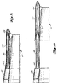
- FIGURE 11 illustrates the disposition of thrust reverser 130, both in its stowed position while the engine operates in forward thrust mode, and as partially deployed (shown in phantom) in reverse thrust mode.
- each blocker panel 136 is pivoted away from its stowed position, moving into a position where it substantially impedes airflow through nozzle 74 and immediately starts to deflect airflow through the partially exposed turning vanes 150, comprising cascaded vane sections 132.
- Linear actuators 98 are also used in thrust reverser 130 to translate aft portion 70 rearwardly away from annular ring 82.
- FIGURE 12 illustrates thrust reverser 130 as it is fully deployed in the reverse thrust mode.
- cascaded vane sections 132 are fully exposed, cantilevered from the aft surface of annular ring 82, and each blocker panel 136 extends downwardly, blocking airflow through nozzle 74. Airflow through the annular duct is thus deflected by turning vanes 150 radially outward and forward.
- Thrust reverser 130 is mechanically simpler than thrust reverser 84 and provides many of its benefits with respect to lightweight construction and relatively low drag when stowed in the forward thrust mode.
- Skin 90, panels 146, and blocking panels 136, i.e., the structure defining pockets 152, provide much the same structural reinforcement in hoop compression and tension as the similar structure in the first embodiment.
- links 138 extend across nozzle 74 when thrust reverser 130 is stowed, they introduce very little drag, since they are formed from relatively thin sheet metal strips with their planar surface aligned in the direction of airflow.
- the tapered shape of the cascaded vane sections 132 and their cantilevered support from the aft edge of annular ring 82 produces a very streamlined design, which accommodates a moderately convergent cone-shaped nacelle.
- the structure of individual pockets 152 resulting from the use of panels 146 between each cascaded vane section greatly increases the stiffness and strength of the aft portion 70, without adding substantial mass of material, as would be required in adapting a prior art design thrust reverser to the relatively large diameter nacelle used on an ultrahigh bypass jet engine.
Landscapes
- Engineering & Computer Science (AREA)
- Chemical & Material Sciences (AREA)
- Combustion & Propulsion (AREA)
- Mechanical Engineering (AREA)
- General Engineering & Computer Science (AREA)
- Structures Of Non-Positive Displacement Pumps (AREA)
- Turbine Rotor Nozzle Sealing (AREA)
Claims (13)
- Schubumkehrvorrichtung (80;130) für ein Bypassgebläsetriebwerk (20;40;60), das eine gebläseinduzierte Luftströmung durch einen Kanal (74;54;74) hat, der durch eine Verkleidung (26;46;66) begrenzt ist, die konzentrisch um wenigstens einen Teil des Triebwerks (20;40;60) angeordnet ist, wobei die Schubumkehrvorrichtung (80;130) folgendes umfaßt:(a) eine Mehrzahl von kaskadierten bzw. gitterartigen Schaufelabschnitten (84;132), von denen jeder mit einem hinteren Rand (82) eines ortsfesten Teils der Verkleidung (26;46;66) verbunden ist und sich davon in einer mit Zwischenraum angeordneten Anordnung bzw. Gruppierung nach rückwärts erstreckt;(b) eine ringförmige Hülse (70), die benachbart der Rückseite des ortsfesten Teils der Verkleidung (26;46;66) in einer Vorwärtsschubbetriebsart angeordnet ist, wobei sich die Hülse (70) konzentrisch um das Triebwerk (20;40;60) erstreckt, sich zu einer Abströmkante verjüngt und Mittel (92;146) zum Begrenzen einer Mehrzahl von Taschen (96;152), die zwischen einer inneren und einer äußeren Strömungsoberfläche (88,90) der ringförmigen Hülse (70) angeordnet sind, umfaßt, wobei jede Tasche (96;152) ein offenes Ende an dem vorderen Ende der ringförmigen Hülse (70) hat und sich nach rückwärts erstreckt, wobei sie nach der Abströmkante der Hülse (70) zu konvergiert, wobei jede Tasche (96;152) so bemessen ist, daß sie ein Ende der kaskadierten bzw. gitterartigen Schaufelabschnitte (84;132) aufnimmt;(c) Stellantriebsmittel (98) zum Bewegen der ringförmigen Hülse (70) nach rückwärts weg von dem ortsfesten Teil der Verkleidung (26;46;66), wobei eine ringförmige Öffnung zwischen dem ortsfesten Teil der Verkleidung (26;46;66) und der ringförmigen Hülse (70) gebildet wird und die kaskadierten bzw. gitterartigen Schaufelabschnitte (84;132) freigelegt werden, wobei sich die kaskadierten bzw. gitterartigen Schaufelabschnitte (84;132) dadurch quer über die ringförmige Öffnung erstrecken, wenn die kaskadierten bzw. gitterartigen Schaufelabschnitte (84;132) aus den Taschen (96;152) in der ringförmigen Hülse (70) zurückgezogen werden; und(d) eine Mehrzahl von Sperrplatten (94;136), von denen jede gegen die innere Strömungsoberfläche (88) der ringförmigen Hülse (70) angeordnet und drehbar an einem Ende mit der ringförmigen Hülse (70) verbunden ist, wobei die Sperrplatten (94;136) Gestängemittel (104;138) aufweisen zum Verschwenken der Sperrplatten (94;136) quer über den Kanal (34;54;74) zum Ablenken der Luftströmung durch die kaskadierten bzw. gitterartigen Schaufelabschnitte (84;132), wenn die Stellantriebsmittel (98) die ringförmige Hülse (70) rückwärts in eine Bremsschubbetriebsart entfalten, wobei die Kanalluftströmung durch die kaskadierten bzw. gitterartigen Schaufelabschnitte (84;132) gewendet wird, um vorwärts bezüglich des Triebwerks (20;40;60) zu strömen, so daß dadurch ein Bremsschub erzeugt wird;dadurch gekennzeichnet, daß die kaskadierten bzw. gitterartigen Schaufelabschnitte (84;132) im wesentlichen sich verjüngend in der radialen Querschnittsdicke sind, wobei sie relativ dünner an ihrem hinteren Ende als an ihrem vorderen Ende sind, wobei die Taschen (96;152) in der ringförmigen Hülse (70) gleichartig verjüngt sind.
- Schubumkehrvorrichtung (80;130) des Anspruchs 1, dadurch gekennzeichnet, daß die kaskadierten bzw. gitterartigen Schaufelabschnitte (84;132) freitragend von dem hinteren Rand (82) des ortsfesten Teils der Verkleidung (26;46;66) sind.
- Schubumkehrvorrichtung (80) des Anspruchs 1 oder 2, dadurch gekennzeichnet, daß die kaskadierten bzw. gitterartigen Schaufelabschnitte (84) drehbar mit dem hinteren Rand (82) der Verkleidung (26;46;66) verbunden sind und sich auswärts verschwenken, wenn sie aus den Taschen (96) zurückgezogen werden, während sie zu der Bremsschubbetriebsart entfaltet werden.
- Schubumkehrvorrichtung (80) des Anspruchs 3, dadurch gekennzeichnet, daß sich die kaskadierten bzw. gitterartigen Schaufelabschnitte (84) aufgrund einer radial nach auswärts gerichteten Vorspannungskraft, welche durch Luftströmung in dem Kanal (34;54;74) bewirkt wird, nach auswärts verschwenken, bis sie einen Anschlag (118) bei voller Entfaltung in der Bremsschubbetriebsart erreichen.
- Schubumkehrvorrichtung (80) des Anspruchs 3 oder 4, gekennzeichnet durch Mittel zum Vorspannen der kaskadierten bzw. gitterartigen Schaufelabschnitte (84) radial nach auswärts nach ihrer vollständig entfalteten Position zu.
- Schubumkehrvorrichtung (80;130) nach irgendeinem der vorhergehenden Ansprüche, dadurch gekennzeichnet, daß die Gestängemittel (104) zwischen einer ersten Länge und einer zweiten Länge, die länger als die erste ist, ausfahrbar sind, und daß sie dahingehend operativ sind, daß sie auf die zweite Länge ausfahren, wenn die ringförmige Hülse (70) nach rückwärts bewegt wird.
- Schubumkehrvorrichtung (80;130) des Anspruchs 6, dadurch gekennzeichnet, daß die Gestängemittel (104) Mittel zum Vorspannen der Gestängemittel zu der ersten Länge umfassen.
- Schubumkehrvorrichtung (80;130) nach irgendeinem der vorhergehenden Ansprüche, dadurch gekennzeichnet, daß die Gestängemittel (104) die Sperrplatten (94) mit der Verkleidung (26;46;66) verbinden.
- Schubumkehrvorrichtung (80;130) nach irgendeinem der Ansprüche 1 bis 7, dadurch gekennzeichnet, daß die Gestängemittel (138) die Sperrplatten (136) mit einer Triebwerksummantelung verbinden.
- Schubumkehrvorrichtung (80;130) nach einem oder mehreren der vorhergehenden Ansprüche, dadurch gekennzeichnet, daß die Mittel (92;146) zum Begrenzen der Mehrzahl von Taschen (96;132) eine Mehrzahl von radial ausgerichteten Platten (92;146) umfassen, die sich zwischen der inneren und äußeren Oberfläche (88;90) der ringförmigen Hülse (70) erstrecken.
- Schubumkehrvorrichtung (80;130) des Anspruchs 10, dadurch gekennzeichnet, daß die Sperrplatten (94;136) mit den radial ausgerichteten Platten (92;146) verbunden sind.
- Hochbypasstriebwerk (20;40;60), das einen Kern (22;42;62), eine ringförmige Verkleidung (26;46;66), die konzentrisch um wenigstens einen Teil des Kerns (22,42;62) gelagert ist und einen ringförmigen Kanal (34;54;74) begrenzt, und eine mit dem hinteren Teil der Verkleidung (26;46;66) zusammenwirkende Schubumkehrvorrichtung (80;130) hat, dadurch gekennzeichnet, daß die Schubumkehrvorrichtung (80;130) von der Art ist, die in einem oder mehreren der vorhergehenden Ansprüche definiert ist.
- Flugzeug, das mit einem oder mehreren Hochbypasstriebwerken, wie sie im Anspruch 12 definiert sind, ausgerüstet ist.
Applications Claiming Priority (2)
| Application Number | Priority Date | Filing Date | Title |
|---|---|---|---|
| US07/135,703 US4807434A (en) | 1987-12-21 | 1987-12-21 | Thrust reverser for high bypass jet engines |
| US135703 | 1987-12-21 |
Publications (3)
| Publication Number | Publication Date |
|---|---|
| EP0321993A2 EP0321993A2 (de) | 1989-06-28 |
| EP0321993A3 EP0321993A3 (de) | 1991-03-06 |
| EP0321993B1 true EP0321993B1 (de) | 1994-09-07 |
Family
ID=22469265
Family Applications (1)
| Application Number | Title | Priority Date | Filing Date |
|---|---|---|---|
| EP88201122A Expired - Lifetime EP0321993B1 (de) | 1987-12-21 | 1988-06-02 | Strahlumkehrvorrichtung für ein Bläsertriebwerk |
Country Status (3)
| Country | Link |
|---|---|
| US (1) | US4807434A (de) |
| EP (1) | EP0321993B1 (de) |
| DE (1) | DE3851420T2 (de) |
Cited By (2)
| Publication number | Priority date | Publication date | Assignee | Title |
|---|---|---|---|---|
| CN101809311B (zh) * | 2007-08-20 | 2012-11-21 | 埃尔塞乐公司 | 用于飞机喷气发动机用叶栅型推力反向器遮挡件的弹簧 |
| WO2013165523A3 (en) * | 2012-02-29 | 2014-01-23 | United Technologies Corporation | Bypass duct with angled drag links |
Families Citing this family (50)
| Publication number | Priority date | Publication date | Assignee | Title |
|---|---|---|---|---|
| US5142862A (en) * | 1990-04-09 | 1992-09-01 | The Boeing Company | Thrust reversing system for high bypass fan engines |
| FR2669679B1 (fr) * | 1990-11-28 | 1994-04-29 | Sud Ouest Conception Aeronauti | Tuyere d'ejection de gaz pour moteur a reaction et moteur a reaction equipe d'une telle tuyere, en particulier moteur du type a flux separes. |
| US5228641A (en) * | 1991-08-15 | 1993-07-20 | Rohr, Inc. | Cascade type aircraft engine thrust reverser with hidden link actuator |
| US5309711A (en) * | 1991-08-21 | 1994-05-10 | Rohr, Inc. | Cascade type thrust reverser for fan jet engines |
| US5239822A (en) * | 1992-01-14 | 1993-08-31 | The Boeing Company | Composite structure for thrust reverser torque box |
| US5778659A (en) * | 1994-10-20 | 1998-07-14 | United Technologies Corporation | Variable area fan exhaust nozzle having mechanically separate sleeve and thrust reverser actuation systems |
| FR2742482B1 (fr) * | 1995-12-19 | 1998-02-06 | Hurel Dubois Avions | Inverseur de poussee a tuyere a section reglable pour moteur d'avion a reaction |
| FR2758161B1 (fr) * | 1997-01-09 | 1999-02-05 | Hispano Suiza Sa | Inverseur de poussee a grilles a installation de verin de commande optimisee |
| US5927647A (en) * | 1997-09-24 | 1999-07-27 | Rohr, Inc. | Blocker door frame pressure structure for translating cowl of cascade thrust reverser for aircraft jet engine |
| US6311928B1 (en) | 2000-01-05 | 2001-11-06 | Stage Iii Technologies, L.C. | Jet engine cascade thrust reverser for use with mixer/ejector noise suppressor |
| US6546715B1 (en) * | 2001-01-25 | 2003-04-15 | Rohr, Inc. | Cascade-type thrust reverser |
| US6968675B2 (en) | 2002-10-29 | 2005-11-29 | Rohr, Inc. | Cascadeless fan thrust reverser with plume control |
| US7124981B2 (en) * | 2003-03-04 | 2006-10-24 | The Boeing Company | Thrust reverser utilizing integrated structural bypass duct |
| GB0608985D0 (en) * | 2006-05-06 | 2006-06-14 | Rolls Royce Plc | Aeroengine thrust reverser |
| FR2902839B1 (fr) * | 2006-06-21 | 2011-09-30 | Aircelle Sa | Inverseur de poussee formant une tuyere adaptative |
| FR2911372B1 (fr) * | 2007-01-15 | 2009-02-27 | Aircelle Sa | Inverseur de poussee translatable pour moteur a reaction |
| FR2915526B1 (fr) * | 2007-04-24 | 2009-05-29 | Aircelle Sa | Dispositif de variation de section de tuyere secondaire associe a un inverseur a portes a dispositif de lissage de veine. |
| CN101939528B (zh) * | 2007-08-08 | 2013-07-24 | 罗尔股份有限公司 | 具有旁通流的面积可调风扇喷嘴 |
| US9759087B2 (en) | 2007-08-08 | 2017-09-12 | Rohr, Inc. | Translating variable area fan nozzle providing an upstream bypass flow exit |
| US8959889B2 (en) | 2008-11-26 | 2015-02-24 | The Boeing Company | Method of varying a fan duct nozzle throat area of a gas turbine engine |
| US8127532B2 (en) * | 2008-11-26 | 2012-03-06 | The Boeing Company | Pivoting fan nozzle nacelle |
| FR2938878B1 (fr) * | 2008-11-26 | 2013-11-08 | Aircelle Sa | Inverseur de poussee pour nacelle de turboreacteur a double flux |
| US8316632B2 (en) * | 2009-02-25 | 2012-11-27 | Spirit Aerosystems, Inc. | Thrust reverser configuration for a short fan duct |
| US8109467B2 (en) * | 2009-04-24 | 2012-02-07 | United Technologies Corporation | Thrust reverser assembly with shaped drag links |
| FR2952128B1 (fr) * | 2009-11-05 | 2011-11-04 | Aircelle Sa | Dispositif d'inverseur de poussee |
| US10041442B2 (en) | 2010-06-11 | 2018-08-07 | United Technologies Corporation | Variable area fan nozzle |
| FR2975730B1 (fr) * | 2011-05-23 | 2013-06-21 | Snecma | Systeme de reduction de la dynamique du segment mobile d'une tuyere deployable pour moteur de fusee |
| FR2987080A1 (fr) * | 2012-02-22 | 2013-08-23 | Aircelle Sa | Inverseur de poussee a grilles pivotantes |
| US9068532B2 (en) * | 2012-07-24 | 2015-06-30 | Rohr, Inc. | Translating sleeve thrust reverser with movable cascade |
| US9989009B2 (en) * | 2012-10-31 | 2018-06-05 | The Boeing Company | Methods and apparatus for sealing variable area fan nozzles of jet engines |
| US10006405B2 (en) * | 2012-11-30 | 2018-06-26 | General Electric Company | Thrust reverser system with translating-rotating blocker doors and method of operation |
| FR3006715B1 (fr) | 2013-06-07 | 2015-06-05 | Aircelle Sa | Inverseur de poussee d’une nacelle de turboreacteur, comprenant des grilles fixees aux capots mobiles |
| US9670877B2 (en) | 2013-07-15 | 2017-06-06 | United Technologies Corporation | Link arm drag reducing device |
| WO2015080785A2 (en) * | 2013-09-19 | 2015-06-04 | United Technologies Corporation | Extended thrust reverser cascade |
| US9611808B2 (en) * | 2014-03-21 | 2017-04-04 | Rohr, Inc. | Blocker door lock mechanism of a thrust reverser for a turbofan engine |
| US9976516B2 (en) * | 2014-03-21 | 2018-05-22 | Rohr, Inc. | Thrust reverser for a turbofan engine |
| WO2016003517A2 (en) * | 2014-04-11 | 2016-01-07 | Crawford Sara C | Variable profile cascade |
| DE102014219068B4 (de) * | 2014-09-22 | 2021-02-18 | Premium Aerotec Gmbh | Fluggasturbinenschubumkehrvorrichtung mit Führungselementen |
| US10309343B2 (en) | 2014-11-06 | 2019-06-04 | Rohr, Inc. | Split sleeve hidden door thrust reverser |
| US10465538B2 (en) | 2014-11-21 | 2019-11-05 | General Electric Company | Gas turbine engine with reversible fan |
| US10113508B2 (en) * | 2014-11-21 | 2018-10-30 | General Electric Company | Gas turbine engine and method of assembling the same |
| US10208708B2 (en) | 2015-01-29 | 2019-02-19 | Rohr, Inc. | Translating cascade hidden blocker door thrust reverser |
| US10473057B2 (en) | 2015-12-14 | 2019-11-12 | Rohr, Inc. | Thrust reverser system with translating elements |
| US9976696B2 (en) | 2016-06-21 | 2018-05-22 | Rohr, Inc. | Linear actuator with multi-degree of freedom mounting structure |
| EP3489547B1 (de) | 2017-11-27 | 2022-05-04 | Rohr, Inc. | Schubumkehrer mit bewegungssteuerungsvorrichtung |
| FR3074852B1 (fr) * | 2017-12-13 | 2021-01-01 | Airbus Operations Sas | Nacelle d'un turboreacteur comportant un volet inverseur et une grille de deviation pour la formation d'un flux d'inversion |
| US10724473B2 (en) * | 2018-06-27 | 2020-07-28 | Spirit Aerosystems, Inc. | System including telescoping hidden drag link assembly for actuating blocker door of thrust reverser |
| FR3090048A1 (fr) * | 2018-12-13 | 2020-06-19 | Airbus Operations | Turboreacteur double flux comportant une serie de lames rotatives pour obturer la veine du flux secondaire |
| CN114483365B (zh) * | 2020-10-26 | 2023-11-10 | 中国航发商用航空发动机有限责任公司 | 航空发动机的核心机试验件、内涵喷管及尾喷管 |
| CN117326071B (zh) * | 2023-10-23 | 2026-01-20 | 江西洪都航空工业股份有限公司 | 一种航空发动机柔性整流罩 |
Family Cites Families (11)
| Publication number | Priority date | Publication date | Assignee | Title |
|---|---|---|---|---|
| US3262271A (en) * | 1965-07-30 | 1966-07-26 | Gen Electric | Thrust reverser |
| FR91242E (fr) * | 1966-10-27 | 1968-05-03 | Breguet Aviat | Dispositif de tuyère d'éjection pour avions à réaction |
| US3503211A (en) * | 1968-04-10 | 1970-03-31 | Rohr Corp | Thrust reverser |
| US3500645A (en) * | 1968-04-10 | 1970-03-17 | Rohr Corp | Thrust reverser |
| GB1583952A (en) * | 1976-07-13 | 1981-02-04 | Short Brothers & Harland Ltd | Gas turbine engines |
| FR2379705A1 (fr) * | 1977-02-08 | 1978-09-01 | Snecma | Dispositif d'inversion de poussee pour turboreacteur d'avion |
| US4391409A (en) * | 1980-09-30 | 1983-07-05 | The Boeing Company | Positioning and control system for fan thrust reverser cowls in a turbofan engine |
| DE3280226D1 (de) * | 1982-09-29 | 1990-09-13 | Boeing Co | Tuervorrichtung fuer schubumkehrblockierung. |
| EP0109219A3 (de) * | 1982-11-12 | 1985-11-13 | LUCAS INDUSTRIES public limited company | Schubumlenkvorrichtung für einen Gasturbinenmotor |
| GB2156004A (en) * | 1984-03-15 | 1985-10-02 | Gen Electric | Thrust modulation device for a gas turbine engine |
| GB2182724B (en) * | 1985-10-08 | 1988-12-07 | Rolls Royce | Gas turbine engine thrust reverser |
-
1987
- 1987-12-21 US US07/135,703 patent/US4807434A/en not_active Expired - Lifetime
-
1988
- 1988-06-02 DE DE3851420T patent/DE3851420T2/de not_active Expired - Lifetime
- 1988-06-02 EP EP88201122A patent/EP0321993B1/de not_active Expired - Lifetime
Cited By (2)
| Publication number | Priority date | Publication date | Assignee | Title |
|---|---|---|---|---|
| CN101809311B (zh) * | 2007-08-20 | 2012-11-21 | 埃尔塞乐公司 | 用于飞机喷气发动机用叶栅型推力反向器遮挡件的弹簧 |
| WO2013165523A3 (en) * | 2012-02-29 | 2014-01-23 | United Technologies Corporation | Bypass duct with angled drag links |
Also Published As
| Publication number | Publication date |
|---|---|
| DE3851420D1 (de) | 1994-10-13 |
| DE3851420T2 (de) | 1995-01-19 |
| EP0321993A3 (de) | 1991-03-06 |
| US4807434A (en) | 1989-02-28 |
| EP0321993A2 (de) | 1989-06-28 |
Similar Documents
| Publication | Publication Date | Title |
|---|---|---|
| US4807434A (en) | Thrust reverser for high bypass jet engines | |
| EP1229237B1 (de) | Kaskadenförmige Schubumkehrvorrichtung | |
| US4731991A (en) | Gas turbine engine thrust reverser | |
| US8869507B2 (en) | Translatable cascade thrust reverser | |
| US3779010A (en) | Combined thrust reversing and throat varying mechanism for a gas turbine engine | |
| EP2570641B1 (de) | Lüftergehäuse mit Schubumkehrgitter, zugehöriger Fan und Gasturbinentriebwerk | |
| US6983588B2 (en) | Turbofan variable fan nozzle | |
| EP2573375B1 (de) | Schubumkehrvorrichtung eines Bläsertriebwerks | |
| US4278220A (en) | Thrust reverser for a long duct fan engine | |
| US5228641A (en) | Cascade type aircraft engine thrust reverser with hidden link actuator | |
| EP1978232B1 (de) | Variable Nebenstromdüse und Schubumkehrer | |
| EP1430212B1 (de) | Schubumlenker mit konvergierender düse | |
| US4998409A (en) | Thrust reverser torque ring | |
| US8783010B2 (en) | Cascade type thrust reverser having a pivoting door | |
| US5313788A (en) | Thrust reversing arrangement for a long duct mixed flow exhaust turbofan engine | |
| EP2551506A2 (de) | Schubumkehr einer Mantelstromtriebwerk | |
| EP1852595A2 (de) | Schubumkehrvorrichtung eines Flug-Triebwerkes | |
| US5852928A (en) | Thrust reverser with extendible pivoting baffle | |
| EP3591204B1 (de) | Schubumkehrer mit verschiebbarem hinterkantenkörper | |
| JPH0762466B2 (ja) | 排気フラップスピードブレーキ | |
| US6050522A (en) | Thrust reverser for a high bypass turbofan engine | |
| EP2886841B1 (de) | Gasturbinenhaube mit Verstelldüse sowie ein dazugehöriges Verfahren | |
| EP3702603B1 (de) | Schubumkehrvorrichtung für die triebwerksgondel eines flugzeugs | |
| US5058828A (en) | Overwing thrust reverser | |
| US11994087B2 (en) | Variable area nozzle and method for operating same |
Legal Events
| Date | Code | Title | Description |
|---|---|---|---|
| PUAI | Public reference made under article 153(3) epc to a published international application that has entered the european phase |
Free format text: ORIGINAL CODE: 0009012 |
|
| AK | Designated contracting states |
Kind code of ref document: A2 Designated state(s): DE FR GB IT NL |
|
| PUAL | Search report despatched |
Free format text: ORIGINAL CODE: 0009013 |
|
| AK | Designated contracting states |
Kind code of ref document: A3 Designated state(s): DE FR GB IT NL |
|
| 17P | Request for examination filed |
Effective date: 19910815 |
|
| 17Q | First examination report despatched |
Effective date: 19921117 |
|
| GRAA | (expected) grant |
Free format text: ORIGINAL CODE: 0009210 |
|
| AK | Designated contracting states |
Kind code of ref document: B1 Designated state(s): DE FR GB IT NL |
|
| PG25 | Lapsed in a contracting state [announced via postgrant information from national office to epo] |
Ref country code: IT Free format text: LAPSE BECAUSE OF FAILURE TO SUBMIT A TRANSLATION OF THE DESCRIPTION OR TO PAY THE FEE WITHIN THE PRESCRIBED TIME-LIMIT;WARNING: LAPSES OF ITALIAN PATENTS WITH EFFECTIVE DATE BEFORE 2007 MAY HAVE OCCURRED AT ANY TIME BEFORE 2007. THE CORRECT EFFECTIVE DATE MAY BE DIFFERENT FROM THE ONE RECORDED. Effective date: 19940907 |
|
| REF | Corresponds to: |
Ref document number: 3851420 Country of ref document: DE Date of ref document: 19941013 |
|
| ET | Fr: translation filed | ||
| PLBE | No opposition filed within time limit |
Free format text: ORIGINAL CODE: 0009261 |
|
| STAA | Information on the status of an ep patent application or granted ep patent |
Free format text: STATUS: NO OPPOSITION FILED WITHIN TIME LIMIT |
|
| 26N | No opposition filed | ||
| REG | Reference to a national code |
Ref country code: GB Ref legal event code: IF02 |
|
| PGFP | Annual fee paid to national office [announced via postgrant information from national office to epo] |
Ref country code: NL Payment date: 20070624 Year of fee payment: 20 |
|
| PGFP | Annual fee paid to national office [announced via postgrant information from national office to epo] |
Ref country code: DE Payment date: 20070731 Year of fee payment: 20 |
|
| PGFP | Annual fee paid to national office [announced via postgrant information from national office to epo] |
Ref country code: GB Payment date: 20070628 Year of fee payment: 20 |
|
| PGFP | Annual fee paid to national office [announced via postgrant information from national office to epo] |
Ref country code: FR Payment date: 20070618 Year of fee payment: 20 |
|
| REG | Reference to a national code |
Ref country code: GB Ref legal event code: PE20 Expiry date: 20080601 |
|
| NLV7 | Nl: ceased due to reaching the maximum lifetime of a patent |
Effective date: 20080602 |
|
| PG25 | Lapsed in a contracting state [announced via postgrant information from national office to epo] |
Ref country code: NL Free format text: LAPSE BECAUSE OF EXPIRATION OF PROTECTION Effective date: 20080602 |
|
| PG25 | Lapsed in a contracting state [announced via postgrant information from national office to epo] |
Ref country code: GB Free format text: LAPSE BECAUSE OF EXPIRATION OF PROTECTION Effective date: 20080601 |