EP0321999B1 - An artificial intra-ocular lens for implantation in the capsular bag - Google Patents
An artificial intra-ocular lens for implantation in the capsular bag Download PDFInfo
- Publication number
- EP0321999B1 EP0321999B1 EP88202516A EP88202516A EP0321999B1 EP 0321999 B1 EP0321999 B1 EP 0321999B1 EP 88202516 A EP88202516 A EP 88202516A EP 88202516 A EP88202516 A EP 88202516A EP 0321999 B1 EP0321999 B1 EP 0321999B1
- Authority
- EP
- European Patent Office
- Prior art keywords
- optic component
- lens
- periphery
- artificial
- ring
- Prior art date
- Legal status (The legal status is an assumption and is not a legal conclusion. Google has not performed a legal analysis and makes no representation as to the accuracy of the status listed.)
- Expired - Lifetime
Links
- 238000002513 implantation Methods 0.000 title description 4
- 238000004873 anchoring Methods 0.000 claims description 11
- 239000002775 capsule Substances 0.000 claims description 10
- 229920003229 poly(methyl methacrylate) Polymers 0.000 claims description 6
- 239000004926 polymethyl methacrylate Substances 0.000 claims description 6
- 239000000126 substance Substances 0.000 claims description 3
- 208000002177 Cataract Diseases 0.000 claims description 2
- 239000004743 Polypropylene Substances 0.000 claims 1
- 239000004792 Prolene Substances 0.000 claims 1
- -1 polypropylene Polymers 0.000 claims 1
- 229920001155 polypropylene Polymers 0.000 claims 1
- 239000000463 material Substances 0.000 description 4
- 210000004087 cornea Anatomy 0.000 description 3
- 210000001747 pupil Anatomy 0.000 description 3
- 230000001179 pupillary effect Effects 0.000 description 3
- 206010036346 Posterior capsule opacification Diseases 0.000 description 1
- 210000004027 cell Anatomy 0.000 description 1
- 230000010339 dilation Effects 0.000 description 1
- 210000002919 epithelial cell Anatomy 0.000 description 1
- 238000003780 insertion Methods 0.000 description 1
- 230000037431 insertion Effects 0.000 description 1
- 238000004519 manufacturing process Methods 0.000 description 1
- 239000012528 membrane Substances 0.000 description 1
- 238000000034 method Methods 0.000 description 1
- 238000013508 migration Methods 0.000 description 1
- 230000005012 migration Effects 0.000 description 1
- 230000002093 peripheral effect Effects 0.000 description 1
- 229940006076 viscoelastic substance Drugs 0.000 description 1
- 239000003190 viscoelastic substance Substances 0.000 description 1
Images
Classifications
-
- A—HUMAN NECESSITIES
- A61—MEDICAL OR VETERINARY SCIENCE; HYGIENE
- A61F—FILTERS IMPLANTABLE INTO BLOOD VESSELS; PROSTHESES; DEVICES PROVIDING PATENCY TO, OR PREVENTING COLLAPSING OF, TUBULAR STRUCTURES OF THE BODY, e.g. STENTS; ORTHOPAEDIC, NURSING OR CONTRACEPTIVE DEVICES; FOMENTATION; TREATMENT OR PROTECTION OF EYES OR EARS; BANDAGES, DRESSINGS OR ABSORBENT PADS; FIRST-AID KITS
- A61F2/00—Filters implantable into blood vessels; Prostheses, i.e. artificial substitutes or replacements for parts of the body; Appliances for connecting them with the body; Devices providing patency to, or preventing collapsing of, tubular structures of the body, e.g. stents
- A61F2/02—Prostheses implantable into the body
- A61F2/14—Eye parts, e.g. lenses or corneal implants; Artificial eyes
- A61F2/16—Intraocular lenses
-
- A—HUMAN NECESSITIES
- A61—MEDICAL OR VETERINARY SCIENCE; HYGIENE
- A61F—FILTERS IMPLANTABLE INTO BLOOD VESSELS; PROSTHESES; DEVICES PROVIDING PATENCY TO, OR PREVENTING COLLAPSING OF, TUBULAR STRUCTURES OF THE BODY, e.g. STENTS; ORTHOPAEDIC, NURSING OR CONTRACEPTIVE DEVICES; FOMENTATION; TREATMENT OR PROTECTION OF EYES OR EARS; BANDAGES, DRESSINGS OR ABSORBENT PADS; FIRST-AID KITS
- A61F2/00—Filters implantable into blood vessels; Prostheses, i.e. artificial substitutes or replacements for parts of the body; Appliances for connecting them with the body; Devices providing patency to, or preventing collapsing of, tubular structures of the body, e.g. stents
- A61F2/02—Prostheses implantable into the body
- A61F2/14—Eye parts, e.g. lenses or corneal implants; Artificial eyes
- A61F2/16—Intraocular lenses
- A61F2002/1681—Intraocular lenses having supporting structure for lens, e.g. haptics
-
- A—HUMAN NECESSITIES
- A61—MEDICAL OR VETERINARY SCIENCE; HYGIENE
- A61F—FILTERS IMPLANTABLE INTO BLOOD VESSELS; PROSTHESES; DEVICES PROVIDING PATENCY TO, OR PREVENTING COLLAPSING OF, TUBULAR STRUCTURES OF THE BODY, e.g. STENTS; ORTHOPAEDIC, NURSING OR CONTRACEPTIVE DEVICES; FOMENTATION; TREATMENT OR PROTECTION OF EYES OR EARS; BANDAGES, DRESSINGS OR ABSORBENT PADS; FIRST-AID KITS
- A61F2/00—Filters implantable into blood vessels; Prostheses, i.e. artificial substitutes or replacements for parts of the body; Appliances for connecting them with the body; Devices providing patency to, or preventing collapsing of, tubular structures of the body, e.g. stents
- A61F2/02—Prostheses implantable into the body
- A61F2/14—Eye parts, e.g. lenses or corneal implants; Artificial eyes
- A61F2/16—Intraocular lenses
- A61F2002/1681—Intraocular lenses having supporting structure for lens, e.g. haptics
- A61F2002/1683—Intraocular lenses having supporting structure for lens, e.g. haptics having filiform haptics
Landscapes
- Health & Medical Sciences (AREA)
- Ophthalmology & Optometry (AREA)
- Cardiology (AREA)
- Oral & Maxillofacial Surgery (AREA)
- Transplantation (AREA)
- Engineering & Computer Science (AREA)
- Biomedical Technology (AREA)
- Heart & Thoracic Surgery (AREA)
- Vascular Medicine (AREA)
- Life Sciences & Earth Sciences (AREA)
- Animal Behavior & Ethology (AREA)
- General Health & Medical Sciences (AREA)
- Public Health (AREA)
- Veterinary Medicine (AREA)
- Prostheses (AREA)
Description
- This invention relates to an artificial lens to be substituted for a natural eye lens which has been clouded by cataract, said artificial lens being designed to be placed in the lens capsule from which the nucleus and cortex of the clouded lens has been removed, said artificial lens including an optic component having centering and anchoring means extending radially beyond its periphery.
- The implantation technique comprises the maximal dilation of the pupillary aperture by chemical means, making an incision along the upper rim of the cornea, and opening the anterior lens capsule at the level of the upper quadrant by means of a horizontal incision slightly curved towards the eye axis. After expression of the natural lens nucleus a space for receiving the artificial lens is available in the capsular bag which is situated between the anterior and the posterior lens capsule. Subsequently, the collapsed capsular bag is filled with a visco-elastic substance, also the portion of the capsular bag situated above the incision. Thus an oval gaping hole is produced through which the artificial lens can pass to reach the capsular bag.
- The artificial lens has to pass three apertures when being placed in the capsular bag, i.e. the incision along the upper rim of the cornea, the pupillary aperture, which is variable, and the incision in the anterior capsule.
- The artificial lens has an optic component of a material (PMMA = polymethyl methacrylate) which is inert in living tissue, as has been proven over the years. This optic portion is smaller than the cataractous lens, so that centering and anchoring means generally called haptics, (such as a ring, arms, loops, etc.) are required to maintain the lens centrally behind the pupil.
- The great flexibility of the arms and ring enables the artificial lens to pass through the comparatively small access aperture of the capsular bag of the lens.
- It is one object of the present invention to provide an artificial lens having as centering and anchoring means, a ring and arms made from the same durable, biologically inert material as the optic component. It is a further object of the invention to provide an artificial lens which, by virtue of its configuration, has a flexibility and deformability which facilitates its implantation in the capsular bag. This is due in part because the optic component and the ring with the arms maintain a co-planar relationship when radial forces are exerted on the ring.
- To that end, according to the present invention, the centering and anchoring means comprise a closed ring extending substantially concentrically about the optic component, said closed ring being connected to the periphery of the optic component by means of two arms, each extending circumferentially between the optic component and the circumferential ring and being connected to the periphery of the optic component and to the ring by means of arm ends, said arm ends extending radially with respect to the periphery of the optic component and widening towards their attachments at the periphery of the optic component and at the circumferential ring, respectively, each arm end connected to the periphery of the optic component being offset by an angle of 15-20° relatively to the end of the other arm connected to the circumferential ring.
- The closed circumferential ring, without protruding portions, reduces the risk of perforation of the posterior lens capsule during insertion. Local, radially inward forces on the ring which flex it inwards, basically only produce a rotation of the optic component in its own plane and not its deflection from this plane in directions perpendicular thereto. Consequently, the artificial lens according to the present invention, can be implanted with greater ease.
- The outside diameter of the artificial lens of about 10 mm can be locally narrowed down to at least 8 mm without the optic component moving out of its plane. By virtue of this feature, the size of apertures can be minimized.
- The rigidity required for maintaining the ring, the connecting arms and the optic component in coplanar relationship, that is to say, the rigidity perpendicular to that plane, is provided by the arm ends extending radially with respect to the periphery of the optic component and widening towards their attachments at the periphery of the optic component and at the circumferential ring, respectively.
- FR-A-2515956 (Lebuisson) discloses an artificial intraocular lens including an optic component having centering and anchoring means formed as arms of which one end is tangentially embedded into the peripheral edge of the optic component.
- A tangential connection of an arm end to the periphery of the optic component results in a smaller rotational torque than in the case of a radial connection. A smaller rotational torque can increase the chance of the optic component leaving its plane during rotation.
- Further at least one of the arms is free ended and the arms are spirally arranged around the optic component. For temporarily compacting the lens assembly so that it may pass small access openings, for example in a capsular bag, the arms are wrapped closely around the optic component. Once the lens is in place the arms are released and they expand to engage the periphery of the capsular bag and thereby fixate the optic component centrally behind the pupil. Open ended arms however can increase the chance of after-cataract because they provide passages for migration of epithelial cells from the periphery to the center of the posterior capsular membrane. A closed ring keeps these cells confined at the periphery of the capsular bag.
- One embodiment of the artificial intra-ocular lens according to the present invention will now be described, by way of example, with reference to the accompanying drawings, in which:
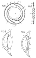
- Fig. 1 is a top view of the artificial lens;
- Fig. 2 is a cross-sectional view taken on the line II-II of Fig. 1;
- Fig. 3 is a vertical cross-sectional view of a detail of a healthy eye;
- Fig. 4 is a cross-sectional view similar to Fig. 3 with an implanted lens; and
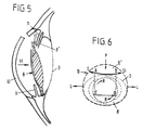
- Figs. 5 and 6 show the principle of the implantation of an intra-ocular lens.
- As shown in Figs. 1 and 2, an
intra-ocular lens 1 includes an optic component orlens body 2 and centering and anchoring means comprising aconcentric ring 3 and two connecting arms 4, 4′ extending along the major part of their lengths circumferentially between thelens body 2 and thering 3. Arms 4, 4′ are connected througharm ends lens body 2, to diametrically opposite places near the ring and near the periphery oflens body 2. Eacharm end lens body 2, is offset by an angle of 15°-20° relatively toarm end 5′, 5 with which the other arm 4′, 4 is connected toring 3. - Fig. 3 is a detail view of a normal eye with a
lens 7 confined in a capsule whose anterior portion is indicated at 8 and its posterior portion at 9. Fig. 3 also shows thecornea 10 and theiris 11 defining thevariable pupillary aperture 12. - Fig. 4 shows the eye detail of Fig. 3, wherein the original lens cortex and nucleus have been replaced by an
intra-ocular lens 1. Arrows K indicate the places where anterior and posterior capsular tissues adhere to each other, thereby fixingring 3 and arms 4, 4′ and retaining thelens body 2 centrally behind the pupil. - Fig. 6 is an elevational view according to the arrow VI of Fig. 5 and these figures show the phase of the introduction of the
intra-ocular lens 1 into the empty capsular bag. In theanterior lens capsule 8 an incision 13 has been made slightly curved convexly towards the optic axis between the points S and S′. The length of this incision is slightly smaller than the diameter of thecircumferential ring 3 of the lens. Consequently,ring 3 should be temporarily narrowed for it to pass incision 13. Such a constriction is concomitant with a rotation of thelens 2 in its own plane, as indicated with arrows R-R in Fig. 6. - In order to bring the upper portion of the
lens body 2 and ofring 3 behind theportion 8′ of theanterior lens capsule 8 situated above incision 13, pressure is exerted onring 3 according to arrow P, which results in a lateral deformation according to arrows L. Thedistance - When the intra-ocular lens has thus been placed in position, the anterior lens capsule is incised in the points A and B up to the points C and D. Subsequently, the flap is severed from C to D to form a window A, B, C, D.
- For the manufacture of the
intra-ocular lens 1, a biconvex lens can be turned from a disc of a suitable material, such as PMMA, with a radial circumferential flange from whichring 3 and arms 4, 4′ can be formed by removing material.
Claims (6)
Applications Claiming Priority (2)
| Application Number | Priority Date | Filing Date | Title |
|---|---|---|---|
| NL8703089A NL8703089A (en) | 1987-12-21 | 1987-12-21 | INTRA-OCULAR ARTIFICIAL LENS FOR IMPLANTATION IN THE LENS CAPSULE. |
| NL8703089 | 1987-12-21 |
Publications (2)
| Publication Number | Publication Date |
|---|---|
| EP0321999A1 EP0321999A1 (en) | 1989-06-28 |
| EP0321999B1 true EP0321999B1 (en) | 1992-03-04 |
Family
ID=19851125
Family Applications (1)
| Application Number | Title | Priority Date | Filing Date |
|---|---|---|---|
| EP88202516A Expired - Lifetime EP0321999B1 (en) | 1987-12-21 | 1988-11-11 | An artificial intra-ocular lens for implantation in the capsular bag |
Country Status (4)
| Country | Link |
|---|---|
| US (1) | US4863463A (en) |
| EP (1) | EP0321999B1 (en) |
| DE (1) | DE3868895D1 (en) |
| NL (1) | NL8703089A (en) |
Families Citing this family (22)
| Publication number | Priority date | Publication date | Assignee | Title |
|---|---|---|---|---|
| US5078740A (en) * | 1990-04-02 | 1992-01-07 | Walman Gerald B | Intraocular lens |
| JPH069582B2 (en) * | 1990-11-16 | 1994-02-09 | 敏之 永本 | Intraocular ring |
| DE69220596T2 (en) * | 1991-04-04 | 1998-02-05 | Menicon Co Ltd | Device for preventing secondary cataracts |
| FR2696339B1 (en) * | 1992-10-02 | 1995-01-27 | Guilbert Guillaume | Intraocular implant with optics that can be inserted through a hole smaller than it. |
| JP3447764B2 (en) | 1993-02-08 | 2003-09-16 | Hoya株式会社 | Disc type intraocular lens |
| US5366501A (en) * | 1993-05-12 | 1994-11-22 | Langerman David W | Intraocular lens with dual 360 degree haptics |
| WO1996029956A1 (en) * | 1995-03-31 | 1996-10-03 | Aziz Yehia Anis | Intraocular lens implant and tool for implanting |
| US6083261A (en) * | 1998-05-28 | 2000-07-04 | Callahan; Wayne B. | Crossed haptics for intraocular lenses |
| US6517577B1 (en) | 1998-05-28 | 2003-02-11 | Thinoptx, Inc. | Crossed haptics for intraocular lenses |
| US7018410B1 (en) * | 2002-08-05 | 2006-03-28 | Mehdi Vazeen | Accommodating intraocular lens |
| US7662180B2 (en) | 2002-12-05 | 2010-02-16 | Abbott Medical Optics Inc. | Accommodating intraocular lens and method of manufacture thereof |
| US8241355B2 (en) * | 2005-10-28 | 2012-08-14 | Abbott Medical Optics Inc. | Haptic for accommodating intraocular lens |
| US8377125B2 (en) | 2006-04-05 | 2013-02-19 | Anew Optics, Inc. | Intraocular lens with accommodation |
| FR2900569B1 (en) * | 2006-05-05 | 2009-01-23 | Pascal Pietrini | INTRAOCULAR LENS FOR IMPLANTATION IN THE CAPSULAR BAG |
| US20080161912A1 (en) * | 2007-01-02 | 2008-07-03 | Alcon, Inc. | Intraocular Lens |
| US8480734B2 (en) | 2007-12-27 | 2013-07-09 | Anew Optics, Inc. | Intraocular lens with accommodation |
| AU2009319753B2 (en) | 2008-11-26 | 2013-11-14 | Anew Iol Technologies, Inc. | Haptic devices for intraocular lens |
| US10010405B2 (en) | 2008-11-26 | 2018-07-03 | Anew Aol Technologies, Inc. | Haptic devices for intraocular lens |
| AU2010266022B2 (en) | 2009-06-26 | 2015-04-23 | Johnson & Johnson Surgical Vision, Inc. | Accommodating intraocular lenses |
| AU2010279561B2 (en) | 2009-08-03 | 2014-11-27 | Johnson & Johnson Surgical Vision, Inc. | Intraocular lens for providing accomodative vision |
| US9084674B2 (en) | 2012-05-02 | 2015-07-21 | Abbott Medical Optics Inc. | Intraocular lens with shape changing capability to provide enhanced accomodation and visual acuity |
| US10441410B2 (en) * | 2016-10-14 | 2019-10-15 | Wayne B. Callahan | Accommodative intraocular lens that ejects post capsular opacification and self-centers |
Family Cites Families (6)
| Publication number | Priority date | Publication date | Assignee | Title |
|---|---|---|---|---|
| FR2515956A1 (en) * | 1981-11-06 | 1983-05-13 | Lebuisson Dan Alexandre | Artificial crystalline lens for implantation after cataract surgery - has retaining finger which retracts elastically to facilitate insertion behind iris |
| US4636212A (en) * | 1982-05-10 | 1987-01-13 | Optical Radiation Corporation | Ultraviolet radiation absorbing intraocular lens |
| GB2124500B (en) * | 1982-07-22 | 1986-04-30 | Mazzocco Thomas R | Improved fixation system for intraocularers structures |
| NL8500527A (en) * | 1984-06-25 | 1986-01-16 | Aziz Yehia Anis | FLEXIBLE LENS FOR THE REAR EYE CHAMBER. |
| US4681586A (en) * | 1986-08-22 | 1987-07-21 | Woods Randall L | Intraocular lens having unitary integral haptic means |
| EP0289449A1 (en) * | 1987-05-01 | 1988-11-02 | Aziz Y. Anis | Posterior chamber lens |
-
1987
- 1987-12-21 NL NL8703089A patent/NL8703089A/en not_active Application Discontinuation
-
1988
- 1988-06-14 US US07/206,511 patent/US4863463A/en not_active Expired - Fee Related
- 1988-11-11 EP EP88202516A patent/EP0321999B1/en not_active Expired - Lifetime
- 1988-11-11 DE DE8888202516T patent/DE3868895D1/en not_active Expired - Lifetime
Also Published As
| Publication number | Publication date |
|---|---|
| EP0321999A1 (en) | 1989-06-28 |
| US4863463A (en) | 1989-09-05 |
| DE3868895D1 (en) | 1992-04-09 |
| NL8703089A (en) | 1989-07-17 |
Similar Documents
| Publication | Publication Date | Title |
|---|---|---|
| EP0321999B1 (en) | An artificial intra-ocular lens for implantation in the capsular bag | |
| US5843184A (en) | Endocapsular tension ring and method of implanting same | |
| US4254510A (en) | Implant lens with biarcuate fixation | |
| EP0916320B1 (en) | Intraocular lens | |
| US4206518A (en) | Intraocular lens device | |
| US5593436A (en) | Capsular bag implants with dual 360 ring structures for inhibiting posterior capsular opacification | |
| CA1217001A (en) | Intraocular posterior chamber lens | |
| US6083261A (en) | Crossed haptics for intraocular lenses | |
| US4463458A (en) | Intraocular lens and implantation method | |
| US4778463A (en) | Artificial intraocular lens | |
| US5769890A (en) | Placement of second artificial lens in eye, to correct for optical defects of first artificial lens in eye | |
| US6881225B2 (en) | Intraocular lenses with a groove for closing the opening of the posterior capsule | |
| EP0403495B1 (en) | ''spare parts'' for ophthalmic surgical procedures | |
| US4127903A (en) | Horizontally mounted intraocular lens and the method of implantation thereof | |
| EP0779063B1 (en) | Capsular bag spreading implant | |
| WO1998005273A1 (en) | Foldable intraocular lens | |
| US11058533B2 (en) | Exocapsular device and method for lens stabilization | |
| EP0032835B1 (en) | Intraocular lens | |
| US4547915A (en) | Intraocular posterior chamber lens | |
| JP3083154B2 (en) | Intraocular lens | |
| WO2019050925A1 (en) | Implantable lens capsule for intraocular lens insertion | |
| US4473910A (en) | Intraocular lens | |
| CA1154904A (en) | Intraocular lens system | |
| US5207708A (en) | Artificial eye lens and method of implanting same | |
| RU2187285C2 (en) | Posterochamber intraocular solid lens |
Legal Events
| Date | Code | Title | Description |
|---|---|---|---|
| PUAI | Public reference made under article 153(3) epc to a published international application that has entered the european phase |
Free format text: ORIGINAL CODE: 0009012 |
|
| AK | Designated contracting states |
Kind code of ref document: A1 Designated state(s): BE DE FR GB IT NL SE |
|
| 17P | Request for examination filed |
Effective date: 19891219 |
|
| 17Q | First examination report despatched |
Effective date: 19910228 |
|
| GRAA | (expected) grant |
Free format text: ORIGINAL CODE: 0009210 |
|
| AK | Designated contracting states |
Kind code of ref document: B1 Designated state(s): BE DE FR GB IT NL SE |
|
| ITF | It: translation for a ep patent filed | ||
| REF | Corresponds to: |
Ref document number: 3868895 Country of ref document: DE Date of ref document: 19920409 |
|
| ET | Fr: translation filed | ||
| PLBE | No opposition filed within time limit |
Free format text: ORIGINAL CODE: 0009261 |
|
| STAA | Information on the status of an ep patent application or granted ep patent |
Free format text: STATUS: NO OPPOSITION FILED WITHIN TIME LIMIT |
|
| 26N | No opposition filed | ||
| EAL | Se: european patent in force in sweden |
Ref document number: 88202516.6 |
|
| PGFP | Annual fee paid to national office [announced via postgrant information from national office to epo] |
Ref country code: NL Payment date: 19960531 Year of fee payment: 8 |
|
| PGFP | Annual fee paid to national office [announced via postgrant information from national office to epo] |
Ref country code: SE Payment date: 19961230 Year of fee payment: 9 Ref country code: FR Payment date: 19961230 Year of fee payment: 9 |
|
| PGFP | Annual fee paid to national office [announced via postgrant information from national office to epo] |
Ref country code: GB Payment date: 19970109 Year of fee payment: 9 |
|
| PGFP | Annual fee paid to national office [announced via postgrant information from national office to epo] |
Ref country code: BE Payment date: 19970116 Year of fee payment: 9 |
|
| PGFP | Annual fee paid to national office [announced via postgrant information from national office to epo] |
Ref country code: DE Payment date: 19970130 Year of fee payment: 9 |
|
| PG25 | Lapsed in a contracting state [announced via postgrant information from national office to epo] |
Ref country code: NL Effective date: 19970601 |
|
| NLV4 | Nl: lapsed or anulled due to non-payment of the annual fee |
Effective date: 19970601 |
|
| PG25 | Lapsed in a contracting state [announced via postgrant information from national office to epo] |
Ref country code: GB Free format text: LAPSE BECAUSE OF NON-PAYMENT OF DUE FEES Effective date: 19971111 |
|
| PG25 | Lapsed in a contracting state [announced via postgrant information from national office to epo] |
Ref country code: SE Free format text: LAPSE BECAUSE OF NON-PAYMENT OF DUE FEES Effective date: 19971112 |
|
| PG25 | Lapsed in a contracting state [announced via postgrant information from national office to epo] |
Ref country code: FR Free format text: THE PATENT HAS BEEN ANNULLED BY A DECISION OF A NATIONAL AUTHORITY Effective date: 19971130 Ref country code: BE Free format text: LAPSE BECAUSE OF NON-PAYMENT OF DUE FEES Effective date: 19971130 |
|
| BERE | Be: lapsed |
Owner name: TJAN TIK TJIANG Effective date: 19971130 |
|
| GBPC | Gb: european patent ceased through non-payment of renewal fee |
Effective date: 19971111 |
|
| PG25 | Lapsed in a contracting state [announced via postgrant information from national office to epo] |
Ref country code: DE Free format text: LAPSE BECAUSE OF NON-PAYMENT OF DUE FEES Effective date: 19980801 |
|
| EUG | Se: european patent has lapsed |
Ref document number: 88202516.6 |
|
| REG | Reference to a national code |
Ref country code: FR Ref legal event code: ST |
|
| PG25 | Lapsed in a contracting state [announced via postgrant information from national office to epo] |
Ref country code: IT Free format text: LAPSE BECAUSE OF NON-PAYMENT OF DUE FEES;WARNING: LAPSES OF ITALIAN PATENTS WITH EFFECTIVE DATE BEFORE 2007 MAY HAVE OCCURRED AT ANY TIME BEFORE 2007. THE CORRECT EFFECTIVE DATE MAY BE DIFFERENT FROM THE ONE RECORDED. Effective date: 20051111 |