EP0322022B1 - Verfahren zur Steuerung einer passiven ferroelektrischen Flüssigkristallwiedergabeanordnung und ferroelektrische Flüssigkristallwiedergabeanordnung - Google Patents
Verfahren zur Steuerung einer passiven ferroelektrischen Flüssigkristallwiedergabeanordnung und ferroelektrische Flüssigkristallwiedergabeanordnung Download PDFInfo
- Publication number
- EP0322022B1 EP0322022B1 EP88202837A EP88202837A EP0322022B1 EP 0322022 B1 EP0322022 B1 EP 0322022B1 EP 88202837 A EP88202837 A EP 88202837A EP 88202837 A EP88202837 A EP 88202837A EP 0322022 B1 EP0322022 B1 EP 0322022B1
- Authority
- EP
- European Patent Office
- Prior art keywords
- bipolar
- row
- signal
- column electrodes
- electrodes
- Prior art date
- Legal status (The legal status is an assumption and is not a legal conclusion. Google has not performed a legal analysis and makes no representation as to the accuracy of the status listed.)
- Revoked
Links
- 238000000034 method Methods 0.000 title claims description 33
- 239000005262 ferroelectric liquid crystals (FLCs) Substances 0.000 title description 13
- 230000005540 biological transmission Effects 0.000 claims description 60
- 239000007788 liquid Substances 0.000 claims description 7
- 230000007704 transition Effects 0.000 claims description 5
- 239000011159 matrix material Substances 0.000 description 8
- 230000001419 dependent effect Effects 0.000 description 6
- 230000000694 effects Effects 0.000 description 3
- 239000000758 substrate Substances 0.000 description 2
- 101100422538 Escherichia coli sat-2 gene Proteins 0.000 description 1
- 230000007423 decrease Effects 0.000 description 1
- 230000002349 favourable effect Effects 0.000 description 1
- 230000004048 modification Effects 0.000 description 1
- 238000012986 modification Methods 0.000 description 1
- 230000008447 perception Effects 0.000 description 1
Images


Classifications
-
- G—PHYSICS
- G02—OPTICS
- G02F—OPTICAL DEVICES OR ARRANGEMENTS FOR THE CONTROL OF LIGHT BY MODIFICATION OF THE OPTICAL PROPERTIES OF THE MEDIA OF THE ELEMENTS INVOLVED THEREIN; NON-LINEAR OPTICS; FREQUENCY-CHANGING OF LIGHT; OPTICAL LOGIC ELEMENTS; OPTICAL ANALOGUE/DIGITAL CONVERTERS
- G02F1/00—Devices or arrangements for the control of the intensity, colour, phase, polarisation or direction of light arriving from an independent light source, e.g. switching, gating or modulating; Non-linear optics
- G02F1/01—Devices or arrangements for the control of the intensity, colour, phase, polarisation or direction of light arriving from an independent light source, e.g. switching, gating or modulating; Non-linear optics for the control of the intensity, phase, polarisation or colour
- G02F1/13—Devices or arrangements for the control of the intensity, colour, phase, polarisation or direction of light arriving from an independent light source, e.g. switching, gating or modulating; Non-linear optics for the control of the intensity, phase, polarisation or colour based on liquid crystals, e.g. single liquid crystal display cells
- G02F1/133—Constructional arrangements; Operation of liquid crystal cells; Circuit arrangements
-
- H—ELECTRICITY
- H04—ELECTRIC COMMUNICATION TECHNIQUE
- H04N—PICTORIAL COMMUNICATION, e.g. TELEVISION
- H04N3/00—Scanning details of television systems; Combination thereof with generation of supply voltages
- H04N3/10—Scanning details of television systems; Combination thereof with generation of supply voltages by means not exclusively optical-mechanical
- H04N3/12—Scanning details of television systems; Combination thereof with generation of supply voltages by means not exclusively optical-mechanical by switched stationary formation of lamps, photocells or light relays
- H04N3/127—Scanning details of television systems; Combination thereof with generation of supply voltages by means not exclusively optical-mechanical by switched stationary formation of lamps, photocells or light relays using liquid crystals
-
- G—PHYSICS
- G09—EDUCATION; CRYPTOGRAPHY; DISPLAY; ADVERTISING; SEALS
- G09G—ARRANGEMENTS OR CIRCUITS FOR CONTROL OF INDICATING DEVICES USING STATIC MEANS TO PRESENT VARIABLE INFORMATION
- G09G3/00—Control arrangements or circuits, of interest only in connection with visual indicators other than cathode-ray tubes
- G09G3/20—Control arrangements or circuits, of interest only in connection with visual indicators other than cathode-ray tubes for presentation of an assembly of a number of characters, e.g. a page, by composing the assembly by combination of individual elements arranged in a matrix no fixed position being assigned to or needed to be assigned to the individual characters or partial characters
- G09G3/34—Control arrangements or circuits, of interest only in connection with visual indicators other than cathode-ray tubes for presentation of an assembly of a number of characters, e.g. a page, by composing the assembly by combination of individual elements arranged in a matrix no fixed position being assigned to or needed to be assigned to the individual characters or partial characters by control of light from an independent source
- G09G3/36—Control arrangements or circuits, of interest only in connection with visual indicators other than cathode-ray tubes for presentation of an assembly of a number of characters, e.g. a page, by composing the assembly by combination of individual elements arranged in a matrix no fixed position being assigned to or needed to be assigned to the individual characters or partial characters by control of light from an independent source using liquid crystals
- G09G3/3611—Control of matrices with row and column drivers
- G09G3/3622—Control of matrices with row and column drivers using a passive matrix
- G09G3/3629—Control of matrices with row and column drivers using a passive matrix using liquid crystals having memory effects, e.g. ferroelectric liquid crystals
-
- G—PHYSICS
- G09—EDUCATION; CRYPTOGRAPHY; DISPLAY; ADVERTISING; SEALS
- G09G—ARRANGEMENTS OR CIRCUITS FOR CONTROL OF INDICATING DEVICES USING STATIC MEANS TO PRESENT VARIABLE INFORMATION
- G09G2310/00—Command of the display device
- G09G2310/06—Details of flat display driving waveforms
-
- G—PHYSICS
- G09—EDUCATION; CRYPTOGRAPHY; DISPLAY; ADVERTISING; SEALS
- G09G—ARRANGEMENTS OR CIRCUITS FOR CONTROL OF INDICATING DEVICES USING STATIC MEANS TO PRESENT VARIABLE INFORMATION
- G09G2310/00—Command of the display device
- G09G2310/06—Details of flat display driving waveforms
- G09G2310/061—Details of flat display driving waveforms for resetting or blanking
-
- G—PHYSICS
- G09—EDUCATION; CRYPTOGRAPHY; DISPLAY; ADVERTISING; SEALS
- G09G—ARRANGEMENTS OR CIRCUITS FOR CONTROL OF INDICATING DEVICES USING STATIC MEANS TO PRESENT VARIABLE INFORMATION
- G09G2320/00—Control of display operating conditions
- G09G2320/02—Improving the quality of display appearance
- G09G2320/0209—Crosstalk reduction, i.e. to reduce direct or indirect influences of signals directed to a certain pixel of the displayed image on other pixels of said image, inclusive of influences affecting pixels in different frames or fields or sub-images which constitute a same image, e.g. left and right images of a stereoscopic display
-
- G—PHYSICS
- G09—EDUCATION; CRYPTOGRAPHY; DISPLAY; ADVERTISING; SEALS
- G09G—ARRANGEMENTS OR CIRCUITS FOR CONTROL OF INDICATING DEVICES USING STATIC MEANS TO PRESENT VARIABLE INFORMATION
- G09G3/00—Control arrangements or circuits, of interest only in connection with visual indicators other than cathode-ray tubes
- G09G3/20—Control arrangements or circuits, of interest only in connection with visual indicators other than cathode-ray tubes for presentation of an assembly of a number of characters, e.g. a page, by composing the assembly by combination of individual elements arranged in a matrix no fixed position being assigned to or needed to be assigned to the individual characters or partial characters
- G09G3/2007—Display of intermediate tones
- G09G3/2011—Display of intermediate tones by amplitude modulation
-
- G—PHYSICS
- G09—EDUCATION; CRYPTOGRAPHY; DISPLAY; ADVERTISING; SEALS
- G09G—ARRANGEMENTS OR CIRCUITS FOR CONTROL OF INDICATING DEVICES USING STATIC MEANS TO PRESENT VARIABLE INFORMATION
- G09G3/00—Control arrangements or circuits, of interest only in connection with visual indicators other than cathode-ray tubes
- G09G3/20—Control arrangements or circuits, of interest only in connection with visual indicators other than cathode-ray tubes for presentation of an assembly of a number of characters, e.g. a page, by composing the assembly by combination of individual elements arranged in a matrix no fixed position being assigned to or needed to be assigned to the individual characters or partial characters
- G09G3/2007—Display of intermediate tones
- G09G3/2014—Display of intermediate tones by modulation of the duration of a single pulse during which the logic level remains constant
Definitions
- the invention relates to a method of driving a display device comprising a ferro-electric liquid crystalline medium between two supporting plates, the first plate comprising a system of row electrodes and the second plate comprising a system of column electrodes determining display elements at the area of the crossings of row and column electrodes, said display elements via bipolar selection signals on the row electrodes and bipolar data signals on the column electrodes reaching transmission states.
- the invention also relates to a device for using such a method
- Such a method is suitable for driving passive matrix displays having a large number of lines. Since the contrast is maintained, the method is very suitable for LCD-TV.
- EP-A-0 137 726 A method of the type mentioned in the opening paragraph is described in EP-A-0 137 726.
- the ON- and OFF-state of a ferro-electric liquid crystal display device (corresponding to a maximum and a minimum transmission state) are maintained as much as possible in order to minimize the exposure of the display elements (pixels) to wrong polarity signals.
- a method according to the invention is characterized in that each time before a bipolar selection signal is applied to a row electrode while bipolar data signals having voltages selected from a voltage range are applied to the column electrodes to realize a range of different transmission states first an auxiliary signal is presented to said row electrode which auxiliary signal has such a duration and height that the display elements associated with said row electrode are brought to an extreme transmission state.
- the invention is based on the recognition that for a given pulse width (for example, equal to one line period or a part thereof) the transmission-voltage characteristic has a relatively small transition range and that the range used for the data voltages can substantially be limited to the width of this transition range.
- a bipolar signal is understood to mean a signal consisting of a sub-signal having a positive voltage and a sub-signal having a negative voltage, the duration and the voltage being substantially equal in absolute sense for the two sub-signals, or the voltage-time product (V.t) being equal.
- An extreme state is understood to mean such a state that the display element is either substantially light-transmissive or non-transmissive.
- bipolar signals results in that possible cross-talk causes the electro-optical transmission state of a display element to vary only around a given setting value (dynamic setting); moreover, in a method according to the invention, the crosstalk may be given such a low amplitude and/or a high frequency that this variation cannot be observed or can hardly be observed by the human eye.
- auxiliary signal For a small number of lines the entire device may be brought to an extreme state in advance by means of an auxiliary signal ("blanking").
- auxiliary signal For larger numbers of lines a bipolar auxiliary signal is preferably presented to a row electrode prior to the bipolar selection signal, which auxiliary signal has such a duration and height of each of the sub-signals that the display element is brought to an extreme state.
- An additional advantage of the use of bipolar signals is the fact that the average voltage across a display element is substantially 0 Volt.
- a first embodiment of a method according to the invention is characterized in that the auxiliary signal and the selection signal are presented within one line period.
- data voltages are presented which have a maximum value covering at least half the voltage range within which the transition from one extreme electro-optical state to another extreme electro-optical state is effected in the transmission-voltage characteristic associated with a quarter of the line period, whilst the absolute value of the parts of the auxiliary signal is at least equal to the sum of the absolute value of the maximum data signal and the absolute value of the parts of the selection signal.
- This method has the advantage of a very low crosstalk.
- auxiliary signal is presented during at least one line period prior to the line period in which selection takes place.
- ferro-electric media having a longer switching time can be chosen or, conversely, media having the same switching time can be used for display devices having shorter line periods or lower voltages.
- Fig. 1 shows the switching behaviour of a ferro-electric display element.
- a display element principally comprises two flat parallel substrates each being provided with electrodes between which the ferro-electric liquid crystal is present.
- FIG. 1a A voltage as shown in Fig. 1a is applied across the display element via the electrodes, while the associated transmission behaviour is shown in Fig. 1b
- the display element is, for example, in such a state that it is substantially light-transmissive (transmission level or transmission value T1).
- a bipolar signal consisting of alternating positive and negative square-wave voltages having a fixed pulse width T w and a voltage of +V0 and -V0, respectively, is presented to the electrodes of the display element.
- the (absolute) value of V0 is chosen to be such that the ferro-electric display element cannot switch to another transmission state at the given pulse width.
- the ferro-electric liquid crystal has such a short switching time that it tends to follow the bipolar signal. This results in a ripple on the transmission level having a value which is dependent on the voltage V0 and on the speed of the ferro-electric liquid crystal.
- a bipolar pulse is presented whose sub-signals 10 and 20 have a pulse width t w , whilst the amplitude is V1.
- V1 and t w are chosen to be such that the display element can be brought substantially to the light-absorbing state (transmission level T0) by the sub-signal 20.
- a bipolar signal having voltage values ⁇ V0 is presented across the display element. In a similar manner as described above, this leads to a ripple on the transmission level T0.
- the average transmission value T0 is constant and the ripple is defined. If the display element forms part of a matrix of display elements, however, successive signals may amplify one another in practice so that the amplitude of the ripple becomes larger, whilst the average transmission level may also shift (at most over a distance equal to the ripple amplitude).
- Fig. 2 shows how the transmission level for the said display element depends on the pulse width t w ( ⁇ t w0 ) when using signals with amplitudes V0, V1.
- the bipolar signals with amplitude ⁇ V0 have sub-signals with a fixed pulse width t w0 .
- the second sub-signal 25 with voltage V1 has a variable pulse width and the first sub-signal 15 with voltage -V1 has a pulse width (2t w0 - t w ).
- the product V1.t w0 is chosen to be such that the display element reaches an extreme state (in this case transmission value T0) by means of the sub-signal 15.
- Intermediate transmission levels grey scales
- These levels are produced because dipoles associated with the ferro-electric liquid crystal molecules may flip over under the influence of the applied voltage.
- Larger or smaller numbers of domains having a different transmission state are formed on a microscopic scale, which domains determine the macroscopic transmission level, or the grey scale of the display element.
- the ratio between the voltages V1 and V0 is approximately 2 to 3 in practice. If ferro-electric liquid crystals are used in a matrix of display elements, it would be possible for such a display element to react, in the case of passive drive and after selection, to the voltages for display elements selected at a later stage. The ferro-electric medium may then be so fast that these data voltages are followed, producing a ripple on the transmission level which has a very disturbing effect, notably in the case of intermediate level setting (grey scale). Since, according to the invention, the data signals are bipolar, it is at least achieved that the grey scales (that is to say, the number of domains) are set around a dynamic balance. However, dependent on the data voltages, and without taking further measures, the ripple may still be considerable.
- grey scales can be obtained by varying the pulse width t w (Fig. 2) between t w1 and t w2 .
- Fig. 3 shows how the transmission level T at a fixed pulse width t w0 and a variable amplitude V of the bipolar signal 25′ depends on the amplitude V.
- An amplitude V1 is chosen for the sub-signal 15′ such that an extreme transmission value is reached.
- a grey scale can be set for a fixed pulse width by variation of the amplitude of the sub-signal 25′.
- V sat - V t the grey scale can be set for a fixed pulse width by variation of the amplitude of the sub-signal 25′.
- a grey scale can be set by voltage modulation within a very small voltage range during a fixed line period or a fixed part thereof (for example, half the line period or a quarter of a line period).
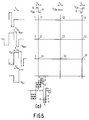
- Fig. 4 shows a practical embodiment of a first method according to the invention.
- the display device is composed of a matrix of display elements 21, 22, 23, ...., 31, 32, 33 which are located at the area of crossings of row electrodes 1, 2, 3, .... and column electrodes 11, 12, 13 which are present on different substrates of a ferro-electric liquid crystal display element.
- the row electrodes are provided with a signal V1 having a bipolar selection signal 4 of ⁇ V sel , which selection signal 4 is preceded by an auxiliary signal or "blanking" signal 5 of ⁇ V bl in which V bl is such a high voltage that the display element reaches an extreme transmission state in the time 1/4 t1. Due to the effect of the subsequent simultaneously presented bipolar selection signals and data signals a desired transmission state is reached.
- the ferro-electric liquid crystal medium switches at each selection, as it were, from an extreme state determined by the "blanking" signal. Preferably, this is the substantially non-transmissive state. This is favourable for reasons of perception.
- the display element reaches the desired transmission value via a voltage variation during selection, at which this advantage is maintained. This is apparent from the voltages across the display elements 21, 22, 23 as shown in Figs. 4a, 4b, 4c, associated with the voltage variation V1 presented to the row electrodes and the voltages V D presented to the column electrodes.
- a signal V Da which is equal to zero Volt during 1/2 t1 is presented to the column electrode 11 and subsequently it assumes the values V Dmax during 1/4 t1 and then the value - V Dmax during 1/4 t1, in which 2V Dmax ⁇ (V sat -V t ) (Fig. 3).
- V Dmax ⁇ (V sat -V t )
- Figs. 4a, 4b, 4c show the actual voltage variation across the display elements 21, 22, 23 if a signal V1 is presented to row electrode 2 during the same line period t1.
- V1 voltage
- Fig. 4a, element 21 voltage values of ⁇ (V sel -V Dmax )
- Fig. 4b, element 22 voltage values of ⁇ (V sel +V Dmax )
- Fig. 4c, element 23 voltage values of ⁇ (V sel +V Dmax )
- the broken lines 6, 7 in the signals a and c in Figs. 4a and 4c, respectively, indicate intermediate grey scales.
- the voltage on the row electrode 2 is zero Volt.
- the setting of the display elements 21, 22, 23, which have acquired a certain setting with the aid of the bipolar data signal V D can only be influenced by voltages on the data electrodes 11, 12, 13.
- Fig. 5 shows a similar method in which a bipolar data signal V Da , V Db , V Dc is presented during the entire line period t1, the first part of the data signal V D coinciding with the first part of the selection signal V sel .
- a bipolar auxiliary signal (“blanking" signal) is presented to the row electrode. Since data signals for a previous row electrode (in this example row electrode 1) are presented during the presentation of this "blanking" signal, the "blanking" signal is not identical for all display elements, but is dependent on the presented signals V D . For the signals V Da , V Db and V Dc this is shown in Fig.
- the signals V Da , V Db and V Dc lead to voltages across the display elements 21, 22, 23 as indicated by a, b and c during selection of row electrode 2. Due to disturbances caused by data voltages which are present, the absolute, effective voltage across a display element during "blanking" may be at least
- a condition for the satisfactory operation is that the bipolar pulse whose parts have a pulse width t1 and an amplitude of at least
- An advantage of this method is that much lower auxiliary voltages (blanking voltages) may suffice.
Landscapes
- Physics & Mathematics (AREA)
- Engineering & Computer Science (AREA)
- Crystallography & Structural Chemistry (AREA)
- Chemical & Material Sciences (AREA)
- General Physics & Mathematics (AREA)
- Computer Hardware Design (AREA)
- Signal Processing (AREA)
- Multimedia (AREA)
- Theoretical Computer Science (AREA)
- Nonlinear Science (AREA)
- Mathematical Physics (AREA)
- Optics & Photonics (AREA)
- Liquid Crystal Display Device Control (AREA)
- Liquid Crystal (AREA)
- Control Of Indicators Other Than Cathode Ray Tubes (AREA)
Claims (10)
- Verfahren zum Steuern einer Anzeigeanordnung mit einem ferroelektrischen flüssigkristallinen Mittel zwischen zwei Trägerplatten, von denen die erste Platte ein System von Zeilenelektroden und die zweite Platte ein System von Spaltenelektroden enthalten, die Anzeigeelemente im Bereich der Kreuzungen von Zeilen- und Speltenelektroden bestimmen, und die Anzeigelemente über bipolare Wählsignale an den Zeilenelektroden und bipolare Datensignale an den Spaltenelektroden Übertragungszustände annehmen, dadurch gekennzeichnet, daß jedesmal vor dem Anlegen eines bipolaren Wählsignals an eine Zeilenelektrode, während bipolare Datensignale mit aus einem Spannungsbereich gewählten Spannungen an die Spaltenelektroden gelegt werden, um einen Bereich verschiedener Übertragungszustände zu verwirklichen, der Zeilenelektrode zunächst ein Hilfssignal zugeführt wird, das eine derartige Dauer und Höhe hat, daß die mit der Zeilenelektrode verknüpften Anzeigeelemente in einen extremen Übertragungszustand versetzt werden.
- Verfahren zum Steuern einer Anzeigeanordnung mit einem ferroelektrischen Flüssigkristallmittel zwischen zwei Trägerplatten, von denen die erste Platte ein System von Zeilenelektroden und die zweite Platte ein System von Spalten elektroden enthalten, die Anzeigeelemente im Bereich der Kreuzungen von Zeilen- und Spaltenelektroden bestimmen, wobei die Anzeigeelemente über bipolare Wählsignale an den Zeilenelektroden und bipolare Datensignale an den Spaltenelektroden Übertragungszustände annehmen, dadurch gekennzeichnet, daß jedesmal direkt vor dem Anlegen eines bipolaren Wählsignals an eine Zeilenelektrode, während bipolare Datensignale mit aus einem Spannungsbereich gewählten Spannungen an die Spaltenelektroden gelegt werden, um einen Bereich verschiedener Übertragungszustände zu verwirklichen, zunächst der Zeilenelektrode ein bipolares Hilfssignal zugeführt wird, wobei das Hilfssignal eine derartige Dauer und Höhe seiner Untersignale hat, daß die mit der Zeilenelektrode verknüpften Anzeigeelemente in einen extremen Übertragungszustand versetzt werden.
- Verfahren nach Anspruch 2, dadurch gekennzeichnet, daß das Hilfssignal und das Wählsignal innerhalb einer Zeilenzeit zugeführt werden.
- Verfahren nach Anspruch 3, dadurch gekennzeichnet, daß in einer vorgegebenen Zeilenzeit, die wenigstens das Vierfache der Schaltzeit eines Anzeigeelements beträgt, Datenspannungen mit einem Höchstwert von wenigstens der Hälfte des Spannungsbereichs zugeführt werden, in dem der Übergang vom einen extremen elektrooptischen Zustand in den anderen extremen elektrooptischen Zustand in der mit einem Viertel der Zeilenzeit verknüpften Übertragungs/Spannungskennlinie erfolgt, während der Absolutwert der Teile des Hilfssignals wenigstens gleich der Summe des Absolutwerts des maximalen Datensignals und des Absolutwerts der Teile des Wählsignals beträgt.
- Verfahren nach Anspruch 2, dadurch gekennzeichnet, daß das Hilfssignal in wenigstens einer Zeilenzeit vor der Zeilenzeit zugeführt wird, in der die Wahl erfolgt.
- Verfahren nach Anspruch 5, dadurch gekennzeichnet, daß das Hilfssignal in der Zeilenzeit vor der Zeilenzeit zugeführt wird, in der die Wahl erfolgt.
- Verfahren nach Anspruch 6, dadurch gekennzeichnet, daß in einer vorgegebenen Zeilenzeit, die wenigstens das Zweifache der Schaltzeit eines Anzeigeelements beträgt, Datenspannungen zugeführt werden, die einen Höchstwert von wenigstens der Hälfte des Spannungsbereichs haben, in dem der Übergang vom einen extremen elektrooptischen Zustand in den anderen extremen elektrooptischen Zustand in der mit der Zeilenzeit verknüpften Übertragungs/Spannungskennlinie erfolgt, während der Unterschied zwischen dem Absolutwert der Teile des Hilfssignals und dem Absolutwert der maximalen Datenspannung wenigstens gleich der Summe des Absolutwerts der maximalen Datenspannung und des Absolutwerts der Teile des Wählsignals ist.
- Verfahren nach einem der Ansprüche 2 bis 7, dadurch gekennzeichnet, daß der letzte Teil des Hilfssignals und der erste Teil des Wählsignals ein gleiches Vorzeichen führen.
- Anzeigeanordnung mit einem ferroelektrischen Flüssigkristallmittel zwischen zwei Trägerplatten, von denen die erste Platte ein System von Zeilenelektroden und die zweite Platte ein System von Spaltenelektroden enthalten, die Anzeigeelemente im Bereich der Kreuzungen von Zeilen- und Spaltenelektroden bestimmen, wobei die Anzeigeanordnung Mittel enthält, mit denen die Anzeigeelemente Übertragungszustände über Bipolar-Wählsignale an den Zeilenelektroden und Bipolardatensignale an den Spaltenelektroden annehmen, dadurch gekennzeichnet, daß die Anordnung außerdem Mittel enthält, mit denen jeweils vor dem Anlegen eines bipolaren Wählsignals an eine Zeilenelektrode, wenn bipolare Datensignale mit aus einem Spannungsbereich gewählten Spannungen an die Spaltenelektroden gelegt werden, um einen Bereich verschiedener Übertragungszustände zu verwirklichen, der Zeilenelektrode zunächst ein Hilfssignal zugeführt wird, das eine derartige Dauer und Höhe hat, daß die mit der Zeilenelektrode verknüpften Anzeigeelemente in einen extremen Übertragungszustand versetzt werden.
- Anzeigeanordnung mit einem ferroelektrischen Flüssigkristallmittel zwischen zwei Trägerplatten, von denen die erste Platte ein System von Zeilenelektroden und die zweite Platte ein System von Spaltenelektroden enthalten, die im Bereich der Kreuzungen von Zeilen- und Spaltenelektroden Anzeigeelemente bestimmen, wobei die Anzeigeanordnung Mittel enthält, mit denen die Anzeigeelemente über bipolare Wählsignale an den Zeilenelektroden und bipolare Datensignale an den Spaltenelektroden Übertragungszustände annehmen können, dadurch gekennzeichnet, daß die Anordnung außerdem Mittel enthält, mit denen jeweils direkt vor dem Anlegen eines bipolaren Wählsignals an eine Zeilenelektrode, während gleichzeitig bipolare Datensignale mit aus einem Spannungsbereich gewählten Spannungen an die Spaltenelektroden gelegt werden, um einen Bereich verschiedener Übertragungspegel zu verwirklichen, zunächst ein bipolares Hilfssignal an die Zeilenelektrode gelegt wird, das eine derartige Dauer und Höhe seiner Untersignale hat, daß die mit der Zeilenelektrode verknüpften Anzeigeelemente in einen extremen Übertragungszustand versetzt werden.
Applications Claiming Priority (2)
| Application Number | Priority Date | Filing Date | Title |
|---|---|---|---|
| NL8703040 | 1987-12-16 | ||
| NL8703040A NL8703040A (nl) | 1987-12-16 | 1987-12-16 | Werkwijze voor het besturen van een passieve ferro-elektrisch vloeibaar kristal weergeefinrichting. |
Publications (2)
| Publication Number | Publication Date |
|---|---|
| EP0322022A1 EP0322022A1 (de) | 1989-06-28 |
| EP0322022B1 true EP0322022B1 (de) | 1994-09-14 |
Family
ID=19851103
Family Applications (1)
| Application Number | Title | Priority Date | Filing Date |
|---|---|---|---|
| EP88202837A Revoked EP0322022B1 (de) | 1987-12-16 | 1988-12-12 | Verfahren zur Steuerung einer passiven ferroelektrischen Flüssigkristallwiedergabeanordnung und ferroelektrische Flüssigkristallwiedergabeanordnung |
Country Status (6)
| Country | Link |
|---|---|
| US (1) | US5047758A (de) |
| EP (1) | EP0322022B1 (de) |
| JP (1) | JP2648625B2 (de) |
| KR (1) | KR890010600A (de) |
| DE (1) | DE3851519T2 (de) |
| NL (1) | NL8703040A (de) |
Families Citing this family (18)
| Publication number | Priority date | Publication date | Assignee | Title |
|---|---|---|---|---|
| JPH0833714B2 (ja) * | 1989-10-16 | 1996-03-29 | シャープ株式会社 | 表示制御装置 |
| JP2682886B2 (ja) * | 1990-04-25 | 1997-11-26 | シャープ株式会社 | 表示装置の駆動方法 |
| GB2249653B (en) * | 1990-10-01 | 1994-09-07 | Marconi Gec Ltd | Ferroelectric liquid crystal devices |
| GB2271211A (en) * | 1992-10-03 | 1994-04-06 | Central Research Lab Ltd | Addressing a ferroelectric liquid crystal display. |
| BE1007478A3 (nl) * | 1993-09-07 | 1995-07-11 | Philips Electronics Nv | Weergeefinrichting met temperatuurcompensatie. |
| US5969207A (en) * | 1994-02-02 | 1999-10-19 | Kozyuk; Oleg V. | Method for changing the qualitative and quantitative composition of a mixture of liquid hydrocarbons based on the effects of cavitation |
| JP3371342B2 (ja) * | 1994-02-14 | 2003-01-27 | ソニー株式会社 | 液晶素子の駆動方法 |
| GB2293907A (en) * | 1994-10-03 | 1996-04-10 | Sharp Kk | Drive scheme for liquid crystal display |
| GB9423051D0 (en) * | 1994-11-15 | 1995-01-04 | Sgs Thomson Microelectronics | A voltage level converter |
| JPH0954307A (ja) * | 1995-08-18 | 1997-02-25 | Sony Corp | 液晶素子の駆動方法 |
| JPH09127483A (ja) * | 1995-11-06 | 1997-05-16 | Sharp Corp | 液晶表示装置 |
| WO1997043685A1 (en) * | 1996-05-10 | 1997-11-20 | Citizen Watch Co., Ltd. | Liquid crystal shutter and its driving method |
| GB2313223A (en) * | 1996-05-17 | 1997-11-19 | Sharp Kk | Liquid crystal device |
| GB9612958D0 (en) * | 1996-06-20 | 1996-08-21 | Sharp Kk | Matrix array bistable device addressing |
| US5937906A (en) * | 1997-05-06 | 1999-08-17 | Kozyuk; Oleg V. | Method and apparatus for conducting sonochemical reactions and processes using hydrodynamic cavitation |
| US5931771A (en) * | 1997-12-24 | 1999-08-03 | Kozyuk; Oleg V. | Method and apparatus for producing ultra-thin emulsions and dispersions |
| WO2003092077A2 (en) * | 2002-04-24 | 2003-11-06 | E Ink Corporation | Electronic displays |
| US9126176B2 (en) | 2012-05-11 | 2015-09-08 | Caisson Technology Group LLC | Bubble implosion reactor cavitation device, subassembly, and methods for utilizing the same |
Citations (2)
| Publication number | Priority date | Publication date | Assignee | Title |
|---|---|---|---|---|
| EP0197742A2 (de) * | 1985-04-03 | 1986-10-15 | Nortel Networks Corporation | Flüssigkristall-Zellenadressierung |
| EP0284134A1 (de) * | 1987-03-17 | 1988-09-28 | Koninklijke Philips Electronics N.V. | Verfahren zur Flüssigkristall-Anzeigeeinrichtungssteuerung und ergänzende Aufzeichnungsvorrichtung |
Family Cites Families (16)
| Publication number | Priority date | Publication date | Assignee | Title |
|---|---|---|---|---|
| GB2146473B (en) * | 1983-09-10 | 1987-03-11 | Standard Telephones Cables Ltd | Addressing liquid crystal displays |
| US4709995A (en) * | 1984-08-18 | 1987-12-01 | Canon Kabushiki Kaisha | Ferroelectric display panel and driving method therefor to achieve gray scale |
| JPS6152630A (ja) * | 1984-08-22 | 1986-03-15 | Hitachi Ltd | 液晶素子の駆動方法 |
| JPH0693166B2 (ja) * | 1984-09-05 | 1994-11-16 | 株式会社日立製作所 | 液晶素子 |
| JPS61156229A (ja) * | 1984-12-28 | 1986-07-15 | Canon Inc | 液晶装置 |
| US4712877A (en) * | 1985-01-18 | 1987-12-15 | Canon Kabushiki Kaisha | Ferroelectric display panel of varying thickness and driving method therefor |
| GB2173337B (en) * | 1985-04-03 | 1989-01-11 | Stc Plc | Addressing liquid crystal cells |
| JP2524100B2 (ja) * | 1985-04-04 | 1996-08-14 | 株式会社精工舎 | 電気光学的表示装置の駆動方法 |
| GB2175725B (en) * | 1985-04-04 | 1989-10-25 | Seikosha Kk | Improvements in or relating to electro-optical display devices |
| JPS6228716A (ja) * | 1985-07-30 | 1987-02-06 | Canon Inc | 液晶装置及び駆動法 |
| EP0214856B1 (de) * | 1985-09-06 | 1992-07-29 | Matsushita Electric Industrial Co., Ltd. | Verfahren zur Ansteuerung eines Flüssigkristallrasterbildschirmes |
| DE3686462T2 (de) * | 1985-09-06 | 1993-01-21 | Matsushita Electric Ind Co Ltd | Verfahren zur ansteuerung eines fluessigkristallrasterbildschirmes. |
| JPS6287941A (ja) * | 1985-10-14 | 1987-04-22 | Seiko Epson Corp | 液晶素子の駆動方法 |
| SE8504760D0 (sv) * | 1985-10-14 | 1985-10-14 | Sven Torbjorn Lagerwall | Electronic addressing of ferroelectric liquid crystal devices |
| JPS62280824A (ja) * | 1986-05-30 | 1987-12-05 | Alps Electric Co Ltd | 液晶表示装置の駆動方法 |
| US4915477A (en) * | 1987-10-12 | 1990-04-10 | Seiko Epson Corporation | Method for driving an electro-optical device wherein erasing data stored in each pixel by providing each scan line and data line with an erasing signal |
-
1987
- 1987-12-16 NL NL8703040A patent/NL8703040A/nl not_active Application Discontinuation
-
1988
- 1988-12-12 DE DE3851519T patent/DE3851519T2/de not_active Revoked
- 1988-12-12 EP EP88202837A patent/EP0322022B1/de not_active Revoked
- 1988-12-13 KR KR1019880016571A patent/KR890010600A/ko not_active Ceased
- 1988-12-15 JP JP63315178A patent/JP2648625B2/ja not_active Expired - Lifetime
-
1990
- 1990-11-09 US US07/614,044 patent/US5047758A/en not_active Expired - Fee Related
Patent Citations (2)
| Publication number | Priority date | Publication date | Assignee | Title |
|---|---|---|---|---|
| EP0197742A2 (de) * | 1985-04-03 | 1986-10-15 | Nortel Networks Corporation | Flüssigkristall-Zellenadressierung |
| EP0284134A1 (de) * | 1987-03-17 | 1988-09-28 | Koninklijke Philips Electronics N.V. | Verfahren zur Flüssigkristall-Anzeigeeinrichtungssteuerung und ergänzende Aufzeichnungsvorrichtung |
Also Published As
| Publication number | Publication date |
|---|---|
| JP2648625B2 (ja) | 1997-09-03 |
| DE3851519T2 (de) | 1995-04-13 |
| DE3851519D1 (de) | 1994-10-20 |
| EP0322022A1 (de) | 1989-06-28 |
| NL8703040A (nl) | 1989-07-17 |
| KR890010600A (ko) | 1989-08-09 |
| US5047758A (en) | 1991-09-10 |
| JPH02914A (ja) | 1990-01-05 |
Similar Documents
| Publication | Publication Date | Title |
|---|---|---|
| EP0322022B1 (de) | Verfahren zur Steuerung einer passiven ferroelektrischen Flüssigkristallwiedergabeanordnung und ferroelektrische Flüssigkristallwiedergabeanordnung | |
| EP0299546B1 (de) | Wiedergabeanordnung und Verfahren zum Steuern einer derartigen Wiedergabeanordnung | |
| EP0197742B1 (de) | Flüssigkristall-Zellenadressierung | |
| EP0473058B1 (de) | Flüssigkristallgerät | |
| US5041823A (en) | Flicker-free liquid crystal display driver system | |
| EP0337780B1 (de) | Anzeigevorrichtung | |
| US5247376A (en) | Method of driving a liquid crystal display device | |
| EP0479530B1 (de) | Ferroelektrische Flüssigkristallvorrichtungen | |
| EP0269150B1 (de) | Verfahren zum Steuern eines Anzeigegerätes und ein für ein solches Verfahren geeignetes Anzeigegerät | |
| EP0324997B1 (de) | Verfahren zur Steuerung einer Wiedergabeanordnung | |
| US5838293A (en) | Driving method and system for antiferroelectric liquid-crystal display device | |
| US6498595B1 (en) | Active matrix liquid crystal display devices | |
| US5298913A (en) | Ferroelectric liquid crystal display device and driving system thereof for driving the display by an integrated scanning method | |
| EP0770898A1 (de) | Verfahren zur ansteuerung einer antiferroelektrischen flüssigkristall-anzeigevorrichtung und dafür geeignetes gerät | |
| GB2294797A (en) | Method of addressing a liquid crystal display | |
| EP0296662B1 (de) | Wiedergabeanordnung und Verfahren zum Steuern einer derartigen Wiedergabeanordnung | |
| EP0616311B1 (de) | Matrixanzeigegerät mit mit Pixels in Reihe Liegenden nichtlinearen Elementen vom Zweiklemmentyp und Steuerverfahren dafür | |
| US5940060A (en) | Ferroelectric liquid crystal cell, method of controlling such a cell, and display | |
| JP2577796B2 (ja) | マトリクス型液晶表示装置のための駆動回路 | |
| KR100236433B1 (ko) | 강유전체 액정 장치를 어드레싱하기 위한 방법과 장치 및 강유전체 액정 장치 | |
| JP3757589B2 (ja) | 液晶表示装置及び液晶表示装置の駆動方法 | |
| EP0614563B1 (de) | Flüssigkristallanseigevorrichtung | |
| EP0717305B1 (de) | Flüssigkristallvorrichtung | |
| WO1989001681A1 (en) | Ferroelectric liquid crystal devices | |
| JP2805252B2 (ja) | 液晶装置 |
Legal Events
| Date | Code | Title | Description |
|---|---|---|---|
| PUAI | Public reference made under article 153(3) epc to a published international application that has entered the european phase |
Free format text: ORIGINAL CODE: 0009012 |
|
| AK | Designated contracting states |
Kind code of ref document: A1 Designated state(s): CH DE FR GB IT LI NL |
|
| 17P | Request for examination filed |
Effective date: 19891218 |
|
| 17Q | First examination report despatched |
Effective date: 19920622 |
|
| GRAA | (expected) grant |
Free format text: ORIGINAL CODE: 0009210 |
|
| AK | Designated contracting states |
Kind code of ref document: B1 Designated state(s): CH DE FR GB IT LI NL |
|
| PG25 | Lapsed in a contracting state [announced via postgrant information from national office to epo] |
Ref country code: IT Free format text: LAPSE BECAUSE OF FAILURE TO SUBMIT A TRANSLATION OF THE DESCRIPTION OR TO PAY THE FEE WITHIN THE PRESCRIBED TIME-LIMIT;WARNING: LAPSES OF ITALIAN PATENTS WITH EFFECTIVE DATE BEFORE 2007 MAY HAVE OCCURRED AT ANY TIME BEFORE 2007. THE CORRECT EFFECTIVE DATE MAY BE DIFFERENT FROM THE ONE RECORDED. Effective date: 19940914 Ref country code: CH Effective date: 19940914 Ref country code: NL Effective date: 19940914 Ref country code: LI Effective date: 19940914 |
|
| REF | Corresponds to: |
Ref document number: 3851519 Country of ref document: DE Date of ref document: 19941020 |
|
| ET | Fr: translation filed | ||
| REG | Reference to a national code |
Ref country code: CH Ref legal event code: PL |
|
| NLV1 | Nl: lapsed or annulled due to failure to fulfill the requirements of art. 29p and 29m of the patents act | ||
| REG | Reference to a national code |
Ref country code: FR Ref legal event code: CD |
|
| PLBI | Opposition filed |
Free format text: ORIGINAL CODE: 0009260 |
|
| 26 | Opposition filed |
Opponent name: CANON KABUSHIKI KAISHA Effective date: 19950614 |
|
| PGFP | Annual fee paid to national office [announced via postgrant information from national office to epo] |
Ref country code: GB Payment date: 19951130 Year of fee payment: 8 |
|
| PGFP | Annual fee paid to national office [announced via postgrant information from national office to epo] |
Ref country code: FR Payment date: 19951220 Year of fee payment: 8 |
|
| PLBF | Reply of patent proprietor to notice(s) of opposition |
Free format text: ORIGINAL CODE: EPIDOS OBSO |
|
| PGFP | Annual fee paid to national office [announced via postgrant information from national office to epo] |
Ref country code: DE Payment date: 19960223 Year of fee payment: 8 |
|
| RDAH | Patent revoked |
Free format text: ORIGINAL CODE: EPIDOS REVO |
|
| RDAG | Patent revoked |
Free format text: ORIGINAL CODE: 0009271 |
|
| STAA | Information on the status of an ep patent application or granted ep patent |
Free format text: STATUS: PATENT REVOKED |
|
| GBPR | Gb: patent revoked under art. 102 of the ep convention designating the uk as contracting state |
Free format text: 960422 |
|
| 27W | Patent revoked |
Effective date: 19960422 |