EP0322038B1 - Digitales Vormodulationsfilter - Google Patents
Digitales Vormodulationsfilter Download PDFInfo
- Publication number
- EP0322038B1 EP0322038B1 EP88202889A EP88202889A EP0322038B1 EP 0322038 B1 EP0322038 B1 EP 0322038B1 EP 88202889 A EP88202889 A EP 88202889A EP 88202889 A EP88202889 A EP 88202889A EP 0322038 B1 EP0322038 B1 EP 0322038B1
- Authority
- EP
- European Patent Office
- Prior art keywords
- impulse response
- filter
- function
- modulation
- modulation filter
- Prior art date
- Legal status (The legal status is an assumption and is not a legal conclusion. Google has not performed a legal analysis and makes no representation as to the accuracy of the status listed.)
- Expired - Lifetime
Links
- 238000012937 correction Methods 0.000 claims description 22
- 230000036962 time dependent Effects 0.000 claims description 4
- 238000001228 spectrum Methods 0.000 description 17
- 238000000034 method Methods 0.000 description 13
- 238000012546 transfer Methods 0.000 description 13
- 230000005540 biological transmission Effects 0.000 description 7
- 230000003595 spectral effect Effects 0.000 description 6
- 230000000694 effects Effects 0.000 description 5
- 230000036961 partial effect Effects 0.000 description 5
- 238000004891 communication Methods 0.000 description 4
- 238000010586 diagram Methods 0.000 description 4
- 238000005316 response function Methods 0.000 description 3
- 238000005070 sampling Methods 0.000 description 3
- 230000003247 decreasing effect Effects 0.000 description 2
- NAWXUBYGYWOOIX-SFHVURJKSA-N (2s)-2-[[4-[2-(2,4-diaminoquinazolin-6-yl)ethyl]benzoyl]amino]-4-methylidenepentanedioic acid Chemical compound C1=CC2=NC(N)=NC(N)=C2C=C1CCC1=CC=C(C(=O)N[C@@H](CC(=C)C(O)=O)C(O)=O)C=C1 NAWXUBYGYWOOIX-SFHVURJKSA-N 0.000 description 1
- 101100234408 Danio rerio kif7 gene Proteins 0.000 description 1
- 101100221620 Drosophila melanogaster cos gene Proteins 0.000 description 1
- 101100398237 Xenopus tropicalis kif11 gene Proteins 0.000 description 1
- 230000002411 adverse Effects 0.000 description 1
- 230000015556 catabolic process Effects 0.000 description 1
- 238000006731 degradation reaction Methods 0.000 description 1
- 238000001514 detection method Methods 0.000 description 1
- 230000010354 integration Effects 0.000 description 1
- 238000012986 modification Methods 0.000 description 1
- 230000004048 modification Effects 0.000 description 1
- 230000010363 phase shift Effects 0.000 description 1
- 230000011664 signaling Effects 0.000 description 1
Images



Classifications
-
- H—ELECTRICITY
- H04—ELECTRIC COMMUNICATION TECHNIQUE
- H04L—TRANSMISSION OF DIGITAL INFORMATION, e.g. TELEGRAPHIC COMMUNICATION
- H04L25/00—Baseband systems
- H04L25/02—Details ; arrangements for supplying electrical power along data transmission lines
- H04L25/03—Shaping networks in transmitter or receiver, e.g. adaptive shaping networks
- H04L25/03828—Arrangements for spectral shaping; Arrangements for providing signals with specified spectral properties
- H04L25/03834—Arrangements for spectral shaping; Arrangements for providing signals with specified spectral properties using pulse shaping
-
- H—ELECTRICITY
- H04—ELECTRIC COMMUNICATION TECHNIQUE
- H04L—TRANSMISSION OF DIGITAL INFORMATION, e.g. TELEGRAPHIC COMMUNICATION
- H04L27/00—Modulated-carrier systems
- H04L27/18—Phase-modulated carrier systems, i.e. using phase-shift keying
- H04L27/20—Modulator circuits; Transmitter circuits
- H04L27/2003—Modulator circuits; Transmitter circuits for continuous phase modulation
- H04L27/2007—Modulator circuits; Transmitter circuits for continuous phase modulation in which the phase change within each symbol period is constrained
- H04L27/2017—Modulator circuits; Transmitter circuits for continuous phase modulation in which the phase change within each symbol period is constrained in which the phase changes are non-linear, e.g. generalized and Gaussian minimum shift keying, tamed frequency modulation
Definitions
- a pre-modulation filter of this structure in which f(t) represents the untruncated impulse response g(t) of the pre-modulation filter, is known from the United States Patent 4,229,821 (PHN 8888).
- Such a pre-modulation filter is used in combination with a modulator of a transmitter for transmitting an angle-modulated carrier signal of a substantially constant amplitude.
- a transmitter is generally intended to transmit binary data signals at a given symbol rate 1/T to a receiver through a transmission channel having a limited bandwidth.
- the modulation techniques to be implemented therein are generally required to exhibit the most efficient use of the bandwidth of an available transmission channel. Even if a modulation technique resulting in an angle-modulated carrier signal of a continuous phase is used thereto, the spectrum of this angle-modulated carrier signal will, nevertheless, generally be wider than that of the equivalent baseband signal.
- a limitation of this spectrum by means of a channel filter is an unattractive solution for radio communication systems since the practical implementation of such a channel filter having accurately prescribed amplitude and phase characteristics and usually a very small relative bandwidth in the radio frequency range, is extremely difficult, also due to the high transmission power.
- a further requirement to be made on modulation techniques to be implemented in radio communication systems is the fact that the corresponding detection techniques result in an error chance as a function of the signal-to-noise ratio, which degrades the least possible with respect to the error chance for optimum baseband transmission of the relevant data signals.
- such a pre-modulation filter can be considered to be a cascade arrangement of an encoding circuit and a low-pass filter.
- Such an encoding circuit has a partial response.
- D k represents a delay over k-symbol periods
- the Patent also states that it is practically advantageous to realise a pre-modulation filter as a digital transversal filter.
- a pre-modulation filter as a digital transversal filter.
- its transfer function is a good approximation of the transfer function that is desired.
- the effect of such a restriction of the duration of the impulse response on the power density spectrum of a modulator output signal is illustrated graphically.
- the variation in the provided graphs implies that a rectangular window function is utilized.
- a pre-modulation filter corrected thus with respect to the impulse response and "softly truncated" results in an overall impulse response that gradually falls off to the value zero at the truncation instants as determined by the chosen width of the window function.
- the continuous phase ⁇ (t) of the output signal of a digital TFM modulator in which such a pre-modulation filter is used also passes through substantially fixed values.
- a further embodiment of a pre-modulation filter of the type described in the Claim 1 is characterized, according to the invention, in that the correction function x(t) is a time independent constant c c , while the following holds for this constant: and the correction factor where
- H( ⁇ ) (1) where the transfer function S( ⁇ ), H( ⁇ ) respectively, is associated to the encoding circuit, low-pass filter respectively, comprised in such a filter and which functions are given by S( ⁇ ) cos2( ⁇ T/2) (2) and respectively, where T represents the symbol interval of a digital signal received by the pre-modulation filter and which has to form the modulate for the TFM modulator.
- F(D) D0 + 2D + D2 (4)
- Fig. 1 illustrates the impulse response g(t) belonging to the transfer function G( ⁇ ) specified by the formulas (1), (2) and (3). According to this Figure the most conducive values of such an impulse response are located in a central interval having a width of 3T, while values outside a central interval having a width of 7T only slightly differ from the value zero.
- the normalised spectral power density P/T as a function of the normalised frequency
- the curve a or b respectively represents the output signal of a TFM modulator in which the pre-modulation filter used therein has an impulse response which is truncated to a width 5T or 7T, respectively.
- a window function having the value is utilized instead of a rectangular window function, in order to obviate the disadvantage which was mentioned with respect to Fig. 2, so that a "soft" truncation is obtained.
- Such a function is represented in Fig. 3.
- a window function w(t) applied in the scope of the invention shows a continuous variation over a time interval comprising one or more intervals T, so that the following holds: (i+1/2)T ⁇
- Such a condition implies, in other words, that the transfer function H( ⁇ ) of the pre-modulation filter is to satisfy the Nyquist-III or I criterion, respectively (in case the relevant modulator is a frequency modulator or phase modulator, respectively).
- the invention is based on the following considerations: when a "hard" truncation is used, which narrows down to the use of a rectangular window function w(t) having a window width that is 5T in the case under consideration, at the positions +5T/2 and -5T/2 the thus truncated impulse response of a pre-modulation filter will abruptly and discontinuously fall off to the value zero.
- a "hard” truncation which narrows down to the use of a rectangular window function w(t) having a window width that is 5T in the case under consideration, at the positions +5T/2 and -5T/2 the thus truncated impulse response of a pre-modulation filter will abruptly and discontinuously fall off to the value zero.
- curve 1 in Fig. 5 the curve 1, 2, 3 respectively, shows on an enlarged scale a portion of a hard or softly truncated impulse response, respectively.
- the power density spectrum is adversely affected.
- This objection can be met by truncating the
- the softly truncated impulse response (curve 3) of a pre-modulation filter is to be modified such that (here in the case of TFM) over the whole truncation range the above conditions a) and b) are continued to be satisfied (curve 2).
- the defining positions are then +3/2T and 5/2T and -3/2T and -5/2T, respectively.
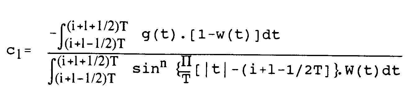
- a correction is made with a sine function of a half interval over one symbol interval.
- n is a positive integer and c a constant.
- this constant c can be computed by means of the relationship: From this it can be derived for the constant c that
- the impulse response at the positions ⁇ 5T/2 gradually falls off to the value zero in a way similar to the one shown in Fig. 5, diagrammatically shown by the curves 2 and 3. This promotes a more gradual variation of the phase function ⁇ (t) due to which the spectrum efficiency is improved.
- the functions w(t) and x(t) are further to show a continuous variation, the variation of the correction function x(t) being determined by the condition that:
- window function w(t) shows a continuous variation over an interval between -(i+1/2)T and -(i+3/2)T and between (i+1/2)T and (i+3/2)T, and
- a correction function x(t) and a window function w(t) can be determined for the impulse response of a pre-modulation filter according to the invention.
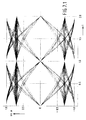
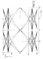
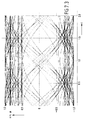
- a pre-modulation filter according to the invention are illustrated in the Figs. 6 and 7.1 to 7.4 which apply to TFM signals.
- the graphs represented in Figs. 6 and 7 are obtained as far as truncation is concerned by using a pre-modulation filter whose impulse response was truncated to a window width of 5T, while the eye pattern according to Fig.7.4 applies to a pre-modulation filter whose impulse response is also corrected with a function having the value sin2( ⁇ t/T) .
- , are representative of angle-modulated output signals of a modulator having a pre-modulation filter whose impulse response
- the requirement is still to be satisfied that the phase ⁇ (t) of the modulator output signal continues to pass through substantially fixed values at sampling instants marking the bit intervals.
- the eye pattern showing the variation of the phase angle ⁇ versus time t indicates to what extent the latter requirement is satisfied.
- the eye pattern as shown in Fig. 7.1 applies to the situation in which the impulse response of the pre-modulation filter used in the modulator is not truncated.
- the sin ⁇ values, detected at the sampling instant whose abscissa value 1.00 is representative, do correspond with the sin ⁇ values that are detected at the sampling instant for the case in which the impulse response of the pre-modulation filter used is not truncated or truncated hard.
- Fig. 7.3 shows that for the case in which the impulse response of the pre-modulation filter is truncated softly, without a correction being introduced, no such correspondence is achieved.
Landscapes
- Engineering & Computer Science (AREA)
- Physics & Mathematics (AREA)
- Computer Networks & Wireless Communication (AREA)
- Signal Processing (AREA)
- Nonlinear Science (AREA)
- Spectroscopy & Molecular Physics (AREA)
- Power Engineering (AREA)
- Digital Transmission Methods That Use Modulated Carrier Waves (AREA)
- Dc Digital Transmission (AREA)
Claims (3)
- Vormodulationsfilter mit einer Gesamtstoßantwort der Gestalt

 - k(t) eine kontinuierliche Funktion ist
 - w(t) = 1, für
 - w(t) für
 - w(t) = 0 für

- Digitales Vormodulationsfilter nach Anspruch 1, dadurch gekennzeichnet, daß A = 1 ist und die Korrekturfunktion x(t) zeitabhängig ist und je Symbolintervall 1 dem untenstehenden Wert entspricht:

- Digitales Vormodulationsfilter nach Anspruch 1, dadurch gekennzeichnet,


Applications Claiming Priority (2)
| Application Number | Priority Date | Filing Date | Title |
|---|---|---|---|
| NL8703084A NL8703084A (nl) | 1987-12-21 | 1987-12-21 | Digitaal premodulatiefilter. |
| NL8703084 | 1987-12-21 |
Publications (2)
| Publication Number | Publication Date |
|---|---|
| EP0322038A1 EP0322038A1 (de) | 1989-06-28 |
| EP0322038B1 true EP0322038B1 (de) | 1993-03-10 |
Family
ID=19851122
Family Applications (1)
| Application Number | Title | Priority Date | Filing Date |
|---|---|---|---|
| EP88202889A Expired - Lifetime EP0322038B1 (de) | 1987-12-21 | 1988-12-15 | Digitales Vormodulationsfilter |
Country Status (5)
| Country | Link |
|---|---|
| US (1) | US5319676A (de) |
| EP (1) | EP0322038B1 (de) |
| JP (1) | JPH01282947A (de) |
| DE (1) | DE3879138T2 (de) |
| NL (1) | NL8703084A (de) |
Families Citing this family (5)
| Publication number | Priority date | Publication date | Assignee | Title |
|---|---|---|---|---|
| JP2643762B2 (ja) * | 1993-04-12 | 1997-08-20 | 日本電気株式会社 | ディジタル化直交変調器 |
| US5386202A (en) * | 1993-11-03 | 1995-01-31 | Sicom, Inc. | Data communication modulation with managed intersymbol interference |
| US5633893A (en) * | 1994-09-29 | 1997-05-27 | Ericsson Inc. | Digital modulation method with controlled envelope variation |
| US5729575A (en) * | 1995-06-20 | 1998-03-17 | Motorola, Inc. | Transmitter and receiver system and method utilizing a pilot carrier notch data encoded signal |
| US6373901B1 (en) * | 1996-04-04 | 2002-04-16 | Motorola, Inc. | Method and apparatus for conditioning modulated signals using window expansion |
Family Cites Families (7)
| Publication number | Priority date | Publication date | Assignee | Title |
|---|---|---|---|---|
| US4141072A (en) * | 1976-12-28 | 1979-02-20 | Xerox Corporation | Frequency domain automatic equalizer using minimum mean square error correction criteria |
| NL7709917A (nl) * | 1977-09-09 | 1979-03-13 | Philips Nv | Systeem voor datatransmissie met behulp van een hoekgemoduleerde draaggolf van constante amplitude. |
| US4261053A (en) * | 1979-04-02 | 1981-04-07 | Satellite Business Systems | PSK Modulator with reduced adjacent channel interference |
| NL189588C (nl) * | 1981-04-01 | 1993-05-17 | Philips Nv | Zender voor hoekgemoduleerde signalen. |
| NL8201533A (nl) * | 1982-04-13 | 1983-11-01 | Philips Nv | Een zender ingericht voor het zenden van fm gemoduleerde signalen. |
| US4731800A (en) * | 1986-10-03 | 1988-03-15 | Hycom Incorporated | Raised-cosine filtering for modems |
| US4757519A (en) * | 1987-10-02 | 1988-07-12 | Hewlett-Packard | Digital premodulation filter |
-
1987
- 1987-12-21 NL NL8703084A patent/NL8703084A/nl not_active Application Discontinuation
-
1988
- 1988-12-15 EP EP88202889A patent/EP0322038B1/de not_active Expired - Lifetime
- 1988-12-15 DE DE8888202889T patent/DE3879138T2/de not_active Expired - Fee Related
- 1988-12-19 JP JP63320347A patent/JPH01282947A/ja active Pending
- 1988-12-21 US US07/289,284 patent/US5319676A/en not_active Expired - Fee Related
Also Published As
| Publication number | Publication date |
|---|---|
| US5319676A (en) | 1994-06-07 |
| DE3879138T2 (de) | 1993-09-02 |
| DE3879138D1 (de) | 1993-04-15 |
| EP0322038A1 (de) | 1989-06-28 |
| NL8703084A (nl) | 1989-07-17 |
| JPH01282947A (ja) | 1989-11-14 |
Similar Documents
| Publication | Publication Date | Title |
|---|---|---|
| US4229821A (en) | System for data transmission by means of an angle-modulated carrier of constant amplitude | |
| US5121412A (en) | All-digital quadrature modulator | |
| US5579342A (en) | Pre-compensated frequency modulation (PFM) | |
| US6628728B1 (en) | Nyquist filter and method | |
| US7345990B2 (en) | Method and apparatus for performing digital communications | |
| US4531221A (en) | Premodulation filter for generating a generalized tamed frequency modulated signal | |
| JPH0777388B2 (ja) | 偏移制御を有するデ−タ周波数変調器 | |
| US5818867A (en) | QPSK/QBL-MSK waveform enhancement | |
| EP0170324B1 (de) | Auf Datensignale ansprechende Vorrichtung zur Erregung eines winkelmodulierten Trägersignals konstanter Amplitude | |
| US6996191B1 (en) | Efficient accurate controller for envelope feedforward power amplifiers | |
| Chung et al. | Generalized tamed frequency modulation | |
| US4320499A (en) | System for multi-level data transmission by means of an angle-modulated carrier having a constant amplitude | |
| EP0155048B1 (de) | Datenübertragungssystem | |
| US20030157905A1 (en) | Transmitter and associated method for reducing the adjacent channel power during wireless communications | |
| US5404379A (en) | Timing recovery method and system | |
| US4011405A (en) | Digital data transmission systems | |
| EP0322038A1 (de) | Digitales Vormodulationsfilter | |
| JPS6347307B2 (de) | ||
| EP0155049B1 (de) | System zur Übertragung von Datensignalen in einem Modulationsband | |
| US5796780A (en) | Coherent modulation of CPM signals | |
| Jung et al. | On the representation of CPM signals by linear superposition of impulses in the bandpass domain | |
| Ishizuka et al. | Improved coherent detection of GMSK | |
| Korn et al. | Q/sup 2/DPSK in the satellite mobile channel with ISI and CSI | |
| JP3428846B2 (ja) | 時間拡散ルートナイキストフィルタ | |
| US10432445B1 (en) | Application of transmit sub-sample dithering apparatus for cyclostationary feature elimination |
Legal Events
| Date | Code | Title | Description |
|---|---|---|---|
| PUAI | Public reference made under article 153(3) epc to a published international application that has entered the european phase |
Free format text: ORIGINAL CODE: 0009012 |
|
| AK | Designated contracting states |
Kind code of ref document: A1 Designated state(s): DE FR GB SE |
|
| 17P | Request for examination filed |
Effective date: 19891218 |
|
| 17Q | First examination report despatched |
Effective date: 19920407 |
|
| GRAA | (expected) grant |
Free format text: ORIGINAL CODE: 0009210 |
|
| AK | Designated contracting states |
Kind code of ref document: B1 Designated state(s): DE FR GB SE |
|
| REF | Corresponds to: |
Ref document number: 3879138 Country of ref document: DE Date of ref document: 19930415 |
|
| ET | Fr: translation filed | ||
| PGFP | Annual fee paid to national office [announced via postgrant information from national office to epo] |
Ref country code: GB Payment date: 19931130 Year of fee payment: 6 |
|
| PGFP | Annual fee paid to national office [announced via postgrant information from national office to epo] |
Ref country code: FR Payment date: 19931222 Year of fee payment: 6 |
|
| PGFP | Annual fee paid to national office [announced via postgrant information from national office to epo] |
Ref country code: SE Payment date: 19931228 Year of fee payment: 6 |
|
| PLBE | No opposition filed within time limit |
Free format text: ORIGINAL CODE: 0009261 |
|
| STAA | Information on the status of an ep patent application or granted ep patent |
Free format text: STATUS: NO OPPOSITION FILED WITHIN TIME LIMIT |
|
| PGFP | Annual fee paid to national office [announced via postgrant information from national office to epo] |
Ref country code: DE Payment date: 19940223 Year of fee payment: 6 |
|
| 26N | No opposition filed | ||
| PG25 | Lapsed in a contracting state [announced via postgrant information from national office to epo] |
Ref country code: GB Effective date: 19941215 |
|
| PG25 | Lapsed in a contracting state [announced via postgrant information from national office to epo] |
Ref country code: SE Effective date: 19941216 |
|
| EAL | Se: european patent in force in sweden |
Ref document number: 88202889.7 |
|
| GBPC | Gb: european patent ceased through non-payment of renewal fee |
Effective date: 19941215 |
|
| PG25 | Lapsed in a contracting state [announced via postgrant information from national office to epo] |
Ref country code: FR Effective date: 19950831 |
|
| PG25 | Lapsed in a contracting state [announced via postgrant information from national office to epo] |
Ref country code: DE Effective date: 19950901 |
|
| EUG | Se: european patent has lapsed |
Ref document number: 88202889.7 |
|
| REG | Reference to a national code |
Ref country code: FR Ref legal event code: ST |