EP0322061A1 - Funksystem, das den Nachrichtenaustausch zwischen einer Gruppe von Stationen gestattet - Google Patents
Funksystem, das den Nachrichtenaustausch zwischen einer Gruppe von Stationen gestattet Download PDFInfo
- Publication number
- EP0322061A1 EP0322061A1 EP88202946A EP88202946A EP0322061A1 EP 0322061 A1 EP0322061 A1 EP 0322061A1 EP 88202946 A EP88202946 A EP 88202946A EP 88202946 A EP88202946 A EP 88202946A EP 0322061 A1 EP0322061 A1 EP 0322061A1
- Authority
- EP
- European Patent Office
- Prior art keywords
- box
- stations
- relay
- station
- access
- Prior art date
- Legal status (The legal status is an assumption and is not a legal conclusion. Google has not performed a legal analysis and makes no representation as to the accuracy of the status listed.)
- Granted
Links
- 238000004891 communication Methods 0.000 claims abstract description 5
- 230000011664 signaling Effects 0.000 claims description 9
- 230000005540 biological transmission Effects 0.000 claims description 7
- 230000015654 memory Effects 0.000 description 10
- 238000000034 method Methods 0.000 description 6
- 230000008859 change Effects 0.000 description 4
- 230000004044 response Effects 0.000 description 4
- 230000006870 function Effects 0.000 description 2
- 230000008520 organization Effects 0.000 description 2
- 230000000717 retained effect Effects 0.000 description 2
- 230000007423 decrease Effects 0.000 description 1
- 238000010586 diagram Methods 0.000 description 1
- 230000008569 process Effects 0.000 description 1
- 230000002123 temporal effect Effects 0.000 description 1
Images



Classifications
-
- H—ELECTRICITY
- H04—ELECTRIC COMMUNICATION TECHNIQUE
- H04W—WIRELESS COMMUNICATION NETWORKS
- H04W48/00—Access restriction; Network selection; Access point selection
- H04W48/20—Selecting an access point
Definitions
- the present invention relates to a radio system for allowing the exchange of information between a set of relay stations and access stations for communications, system using at least one common signaling channel which is provided in particular for establishing relationships between stations. -relays and access stations and in which the relay stations can transmit a first mark in the first determined moments while the access stations include means for connecting at these determined moments on said channel.
- Such a device is known from British patent GB 1,591,159.
- the marks are constituted by tones: a first to signify that the relay station which transmits it wants to send a message to the access stations which receive it and a second to signify that the relay station which transmits it has no message to broadcast.
- the device will only be sensitive to the first tone if its level is higher than the second tones received.
- This known system has a first drawback due to the fact that it is ill-suited to networks using a signaling channel transmitting digital type information, as is the case with the RAMAGE network.
- This network is described in the article: "RAMAGE -a private mobile radiotelephone network" by G. Banquet, J.P. Pittion, M.Coudreuse and published in "Communications engineering International, September 1986".
- One of the aims of the invention is to provide a radio system which may be suitable for a RAMAGE network.
- a system of the kind mentioned in the preamble is remarkable in that this mark is formed by a digital code defining the relay station which transmits it and that its recognition at the level of the access stations is a criterion for establishing said relationship.
- Another object of the invention is to provide a radio system using several criteria to establish the access station-station-relay relationship.
- a system of the kind mentioned in the preamble for which a signaling channel is used to transmit in determined second moments, each of which is assigned to a relay a second mark in digital form is remarkable, according to a feature of the invention, in that to establish said relationship, a second criterion is used which consists in analyzing the quality of transmission of the second brand.
- the references R1, R2, and R3 show the location of different relay stations. These different relay stations R1, R2 and R3 can be received within zones Z1, Z2, Z3.
- the problem that arises therefore, first of all, for station M to be connected to one of the relay stations R1, R2 or R3.
- a signaling channel is used, the organization of which is shown in FIG. 2.
- the relay station R1 transmits an M code (R1) comprising its identification code accompanied by an error detecting code.
- the station R2 will transmit at times t3 and t6 an M code (R2) while the station R3 will send at times t4 and t7 an M code (R3).
- M (R1) + M (R2) + M (R3) the recognition of only one of these marks at the level of the receivers of the access stations indicates that this determines the best received relay station.
- TR and MTR the frame and multiframe codes necessary to have a good synchronization of the system.
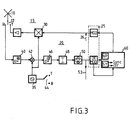
- FIG. 3 shows, in part, the structure of an access station. Parts not shown are not necessary for understanding the invention.
- Reference 10 in this figure 3 shows the antenna of the station. This antenna is used both in transmission and in reception.
- An antenna relay 12 with two positions R and T makes it possible to connect this antenna 10 either to a transmitting branch 15, the relay being in position T or to a receiving branch 20, the relay then being in position R.
- a modem circuit 25 is used to receive and transmit digital data transmitted in particular in the signaling channel. The MOD modulation part of this modem 25 is connected to the input of the transmission branch 15 just like the sound circuit (this is represented by the dotted arrow 26).
- a modulator 30 gives a carrier to its input signals; the carrier comes from a local oscillator which is also used by the reception branch 20.
- a high-frequency amplifier 40 provides the level required by the antenna for transmission.
- the reception branch 20 firstly comprises a preamplification stage 40 for amplifying the signals coming from the antenna 10, a frequency change stage 42 is connected at the output of stage 42.
- This frequency change stage also uses the local oscillator 35. It should be noted that its frequency must change depending on whether one is transmitting or receiving. This change is symbolized by the two-position contactor 44 R and T operated at the same time as the antenna relay 12. Thus the frequency of the output signal varies not only by the deviation from the duplex but also by the value of the intermediate frequency.
- a frequency discriminator 50 which follows provides, on the one hand, information to the demodulation part DEMOD of the 25 modem and on the other hand speech signals to the sound part.
- a synchronization part Sy has been distinguished which provides , as a function of the recognized TR and MTR codes, of the iSY signals giving as a function of time the number of the expected temporal locations of the marks coming from the various relay stations.
- This Sy part also provides a Sync signal indicating that synchronization on the signaling link is retained.
- the flow diagram of FIG. 4a begins with a box K0 indicating the start of the running of the operating program which will be described.
- the following box K1 indicates a test on the value of the Sync signal.
- the value "1" indicates that synchronization is obtained and we then go to box K2. This test is performed as long as the Sync value is not equal to 1.
- Box K2 represents the program initialization phase.
- Different counters m1, m2, ... m i , ... m N are set to zero, each of them being assigned to a relay and N therefore represents the number of relay stations considered.
- a counter T is also set to zero. This counter T increments on the frames during which the receiver M compares the quality of reception of the marks received from the different stations R1, R2, ... RN.
- an indicator C is set to "0" and the number of the relay "i” detected is determined by the signal iSy and not by the code M (Ri), and it is set to 10 in a memory location NR. If the Ne is less than 10, we go to box K6; here the indicator C is set to "1" and the number of the relay "i” is determined by the recognition of the mark M (Ri), the number of errors Ne is stored in the memory NR.
- box K10 From boxes K5 or K6, we go to box K10 where we examine the iSy information to know if we are dealing with the times (t1, t8, ...) when all the brands of relay stations are transmitted at the same time ; if this is the case, we go to box K11, if this is not the case in box K12.
- box K11 a test is carried out on the indicator C; if this indicates that the mark M (Ri) has been received in good conditions, the counter m i which is allocated to it is incremented (box K13). If the mark was badly received, we go to box K14. Box K12 therefore relates to cases where a mark has been recognized outside the times when all the marks are transmitted simultaneously. In this box K12 a correction is made to the quality of the signal, that is to say that this quality decreases by the number of errors supplied during the procedure in box K3.
- the counter m i relating to the mark, examined in box K5 or K6, is examined; if the content of the counter m i is greater than or equal to 3, we then examine (see box K15), the content of the other counters m j containing the other relay stations (that is to say that j can take all the values from 1 to N except the value i). If the tests relating to the "i" given and carried out in boxes K14 and K15 prove to be positive, it is then examined (see box K16) if the access station is not already in relation with the station Ri; this is indicated by the contents of a LOC memory.
- box K22 we test an RC indicator indicating whether a response has been received; if the test is negative we return to box K3.
- Box K23 which follows is a procedure for decoding the response; if this is positive, we go to box K30 where the relation to the station Ri becomes effective.
- box K40 if we have made a relationship request. If this is not the case, box K41 is initialized for a search loop for the relays R i that we receive best.
- an index p is set to zero, the memory MM1 in which we will put the maximum value of the contents of the memories m i , the memory MM2 in which we will put the value immediately lower than the previous maximum value, value taken from the contents of memory m i and finally memory Q into which the maximum value of the contents of memories Q i will be put .
- the search for these three values is carried out in the loop including boxes K42 to K49.
- Box K42 corresponds to the increment of the index p used in this loop.
- Box K43 leaves the loop when the index p is greater than N, N being the number of relays.
- the boxes K44 to K47 explain the search for the values MM1 and MM2 previously explained; in box K45, the value of the index p is also stored for which the value m p is maximum.
- the boxes K48 and K49 search for the maximum value contained in the counters Q i , as well as for the index p for which this maximum value is obtained.
- box K50 we test if the difference between the values MM1 and MM2 is greater than or equal to 3. If this is the case, we test box K51 if the note Q i , with the same index as m j contained in MM1, is greater than a minimum value Q min . If this is the case, the value of the index is retained in box K52 in order to make an attempt at relating to the corresponding relay. Otherwise, box K53 is tested if the value Q is greater than Q min . If it is not the case, one directs oneself on box K54 and one stops the program by leaving, for example, to the user the care to relaunch other attempts. If Q is greater than Q min , we move to box K55.
- Case K55 we examine if we are already in relation with the relay R j . If this is the case, we return to K1. Otherwise, in box K56, the indicator CX is set to 1, then in box K57, the same procedure is carried out on relay R j as indicated in box K10. Then we go to box K58 which is, finally, a waiting phase. This box K58 also comes after the box K40 already described, and relates to the case where the test on CX is positive. When the response comes back (box K59) it is tested (box K60); if it is positive, connect to the relay station thus determined, box K62, then return to K1.
- the Applicant has chosen the following parameters for proper operation of the system.
- the multiframe comprising a common mark contains q times the frame sequence of the different marks of each of the N relay stations.
- QMAX 80q
- Q min 20q
- TMAX 8 (Nq + 1)
- the present invention has been described with a flowchart showing a preference for the first criterion to be satisfied in the first place, that is to say the criterion based on the recognition of marks, it goes without saying that without departing from the Within the framework of the invention, the second criterion can also be satisfied, that is to say the criterion based on the quality of transmission of the marks. This can be done by reversing the order of tests K50 and K53.
Landscapes
- Engineering & Computer Science (AREA)
- Computer Security & Cryptography (AREA)
- Computer Networks & Wireless Communication (AREA)
- Signal Processing (AREA)
- Mobile Radio Communication Systems (AREA)
- Radio Relay Systems (AREA)
Applications Claiming Priority (2)
| Application Number | Priority Date | Filing Date | Title |
|---|---|---|---|
| FR8718048A FR2625389B1 (fr) | 1987-12-23 | 1987-12-23 | Systeme radioelectrique pour permettre l'echange d'informations entre un ensemble de stations |
| FR8718048 | 1987-12-23 |
Publications (2)
| Publication Number | Publication Date |
|---|---|
| EP0322061A1 true EP0322061A1 (de) | 1989-06-28 |
| EP0322061B1 EP0322061B1 (de) | 1994-08-24 |
Family
ID=9358239
Family Applications (1)
| Application Number | Title | Priority Date | Filing Date |
|---|---|---|---|
| EP88202946A Expired - Lifetime EP0322061B1 (de) | 1987-12-23 | 1988-12-19 | Funksystem, das den Nachrichtenaustausch zwischen einer Gruppe von Stationen gestattet |
Country Status (5)
| Country | Link |
|---|---|
| US (1) | US4995097A (de) |
| EP (1) | EP0322061B1 (de) |
| JP (1) | JPH01202936A (de) |
| DE (1) | DE3851211T2 (de) |
| FR (1) | FR2625389B1 (de) |
Cited By (4)
| Publication number | Priority date | Publication date | Assignee | Title |
|---|---|---|---|---|
| FR2656178A1 (fr) * | 1989-12-06 | 1991-06-21 | Motorola Inc | Procede et appareil permettant d'augmenter la reutilisation de frequences sur une meme voie dans un reseau de radiocommunication de donnees a plusieurs stations. |
| FR2666465A1 (fr) * | 1990-09-03 | 1992-03-06 | Alcatel Radiotelephone | Dispositif de selection de signaux de reception selon leur puissance. |
| FR2693330A1 (fr) * | 1992-07-01 | 1994-01-07 | Motorola Inc | Procédé permettant d'effectuer un transfert assisté pour poste mobile dans un système de télécommunications. |
| FR2701341A1 (fr) * | 1993-02-08 | 1994-08-12 | Trt Telecom Radio Electr | Système de radiocommunications comportant une pluralité de stations de base. |
Families Citing this family (2)
| Publication number | Priority date | Publication date | Assignee | Title |
|---|---|---|---|---|
| FR2644655A1 (fr) * | 1989-03-17 | 1990-09-21 | Trt Telecom Radio Electr | Procede de transmission d'informations dans un reseau de transmission de donnees par voie radioelectrique et systeme pour lequel est mis en oeuvre le procede |
| US5182753A (en) * | 1990-03-20 | 1993-01-26 | Telefonaktiebolaget L M Ericsson | Method of transmitting signaling messages in a mobile radio communication system |
Citations (5)
| Publication number | Priority date | Publication date | Assignee | Title |
|---|---|---|---|---|
| FR2376570A1 (fr) * | 1976-12-30 | 1978-07-28 | Siemens Ag | Procede pour realiser la transmission numerique d'informations par radiocommunications |
| GB1591159A (en) * | 1977-11-04 | 1981-06-17 | British Broadcasting Corp | Message-broadcasting systems |
| EP0036146A1 (de) * | 1980-03-11 | 1981-09-23 | Siemens Aktiengesellschaft | Mobiles Funknetz |
| EP0069275A1 (de) * | 1981-07-02 | 1983-01-12 | Trancom AB | Apparat zur Kommunikation mit einem Fahrzeugpark |
| EP0145098A2 (de) * | 1983-12-09 | 1985-06-19 | Telecommunications Radioelectriques Et Telephoniques T.R.T. | Verfahren für eine in beiden Richtungen wirksame Funkverbindung zwischen einer Feststation und einer Mobilstation |
Family Cites Families (4)
| Publication number | Priority date | Publication date | Assignee | Title |
|---|---|---|---|---|
| DE3133347A1 (de) * | 1981-08-22 | 1983-03-10 | TE KA DE Felten & Guilleaume Fernmeldeanlagen GmbH, 8500 Nürnberg | Verfahren zum zugreifen auf uebertragungskanaele eines nachrichtenuebertragungssystems |
| DE3527330A1 (de) * | 1985-07-31 | 1987-02-05 | Philips Patentverwaltung | Digitales funkuebertragungssystem mit verbindungsbegleitenden organisationskanal im zeitmultiplexrahmen |
| DE3527331A1 (de) * | 1985-07-31 | 1987-02-05 | Philips Patentverwaltung | Digitales funkuebertragungssystem |
| DE3607687A1 (de) * | 1986-03-08 | 1987-09-10 | Philips Patentverwaltung | Verfahren und schaltungsanordnung zum weiterschalten einer funkverbindung in eine andere funkzelle eines digitalen funkuebertragungssystems |
-
1987
- 1987-12-23 FR FR8718048A patent/FR2625389B1/fr not_active Expired - Lifetime
-
1988
- 1988-12-19 EP EP88202946A patent/EP0322061B1/de not_active Expired - Lifetime
- 1988-12-19 DE DE3851211T patent/DE3851211T2/de not_active Expired - Fee Related
- 1988-12-21 US US07/289,283 patent/US4995097A/en not_active Expired - Fee Related
- 1988-12-23 JP JP63323777A patent/JPH01202936A/ja active Pending
Patent Citations (5)
| Publication number | Priority date | Publication date | Assignee | Title |
|---|---|---|---|---|
| FR2376570A1 (fr) * | 1976-12-30 | 1978-07-28 | Siemens Ag | Procede pour realiser la transmission numerique d'informations par radiocommunications |
| GB1591159A (en) * | 1977-11-04 | 1981-06-17 | British Broadcasting Corp | Message-broadcasting systems |
| EP0036146A1 (de) * | 1980-03-11 | 1981-09-23 | Siemens Aktiengesellschaft | Mobiles Funknetz |
| EP0069275A1 (de) * | 1981-07-02 | 1983-01-12 | Trancom AB | Apparat zur Kommunikation mit einem Fahrzeugpark |
| EP0145098A2 (de) * | 1983-12-09 | 1985-06-19 | Telecommunications Radioelectriques Et Telephoniques T.R.T. | Verfahren für eine in beiden Richtungen wirksame Funkverbindung zwischen einer Feststation und einer Mobilstation |
Non-Patent Citations (2)
| Title |
|---|
| COMMUTATION & TRANSMISSION, vol. 8, no. 1, 1986, pages 19-30, Paris, FR; G. BANQUET et al.: "Ramage, un réseau radiotéléphonique mobile privé" * |
| THE 36TH IEEE VEHICULAR TECHNOLOGY CONFERENCE, 20-22 mai 1986, Dallas, pages 334-341, New York, US; K. IMAMURA et al.: "Mobile communication control using multi-transmitter simul/sequential casting (MSSC)" * |
Cited By (5)
| Publication number | Priority date | Publication date | Assignee | Title |
|---|---|---|---|---|
| FR2656178A1 (fr) * | 1989-12-06 | 1991-06-21 | Motorola Inc | Procede et appareil permettant d'augmenter la reutilisation de frequences sur une meme voie dans un reseau de radiocommunication de donnees a plusieurs stations. |
| FR2666465A1 (fr) * | 1990-09-03 | 1992-03-06 | Alcatel Radiotelephone | Dispositif de selection de signaux de reception selon leur puissance. |
| EP0475248A1 (de) * | 1990-09-03 | 1992-03-18 | Alcatel Mobile Communication France | Anordnung zur Auswahl von Empfangssignalen nach Leistung |
| FR2693330A1 (fr) * | 1992-07-01 | 1994-01-07 | Motorola Inc | Procédé permettant d'effectuer un transfert assisté pour poste mobile dans un système de télécommunications. |
| FR2701341A1 (fr) * | 1993-02-08 | 1994-08-12 | Trt Telecom Radio Electr | Système de radiocommunications comportant une pluralité de stations de base. |
Also Published As
| Publication number | Publication date |
|---|---|
| DE3851211T2 (de) | 1995-04-20 |
| DE3851211D1 (de) | 1994-09-29 |
| US4995097A (en) | 1991-02-19 |
| FR2625389B1 (fr) | 1990-05-04 |
| JPH01202936A (ja) | 1989-08-15 |
| FR2625389A1 (fr) | 1989-06-30 |
| EP0322061B1 (de) | 1994-08-24 |
Similar Documents
| Publication | Publication Date | Title |
|---|---|---|
| CA2172672C (fr) | Procede de reception multicapteur d'une station de base fixe d'un reseau de communication echangeant des donnees avec des mobiles, et dispositif pour sa mise en oeuvre | |
| US5726893A (en) | Cellular telephone with voice-in-data modem | |
| EP0702866A1 (de) | Signalisationspaket fur kommunikationssystem mit modulierter referenz die einem zeitabhangigen gesetz folgt | |
| CA2170803C (en) | Fast acquisition of gmsk-modulated signal for cdpd applications | |
| FR2904168A1 (fr) | Systeme d'estimation de la qualite de reception d'une transmission numerique. | |
| EP0322061B1 (de) | Funksystem, das den Nachrichtenaustausch zwischen einer Gruppe von Stationen gestattet | |
| US6256494B1 (en) | Method of and apparatus for estimating a characteristic of a signal | |
| US5930267A (en) | Frame synchronization for asynchronous transmission | |
| CA1236228A (fr) | Procedes de diffusion et de reception de programmes sonores de haute qualite et dispositif de reception | |
| US6393071B1 (en) | Circuit and method of identifying a burst frequency | |
| FR2738982A1 (fr) | Systeme de telecommunications comportant une pluralite d' unites portables et au moins une unite de base formant un systeme de communication sans fil | |
| FR2750284A1 (fr) | Procede permettant d'identifier des combines actifs dans un systeme de telephone sans fil | |
| US4069454A (en) | Transmitter-receiver employing automatic channel hunting and selection | |
| CA2041764C (fr) | Dispositif d'evaluation d'ecart de frequence | |
| FR3084555A1 (fr) | Procede et systeme de geolocalisation d’un terminal a portee d’un dispositif emetteur d’interet | |
| US5854808A (en) | Methods and apparatus for detecting the presence of a prescribed signal in a channel of a communications system | |
| EP1303071A1 (de) | Verfahren und Vorrichtung zur automatischen Ratenauswahl für Hochfrequenzübertragungen | |
| FR2490428A1 (fr) | Dispositif de recherche de la frequence d'accord d'un recepteur radioelectrique a modulation de frequence | |
| FR2546693A1 (fr) | Annuleur d'echo a filtre numerique adaptatif pour systeme de transmission | |
| FR3089736A1 (fr) | Procédé de détermination de la distance entre un dispositif d’authentification et un véhicule | |
| EP1801608A1 (de) | Verfahren und System zur Vorortung zur Unterstützung von Satellitenfunknavigationssystemen | |
| EP0768803A1 (de) | Kanalabtastungsprotokoll für tragbare Funktelefone | |
| FR2745144A1 (fr) | Procede d'etablissement d'une liaison de transmission de donnees numeriques a travers le reseau radiotelephonique gsm et procede de test de la qualite de la liaison | |
| EP1119124A1 (de) | Empfängersynchronisierung mit einer Sendestation in einem TDMA-Übertragungssystem | |
| EP4327571A1 (de) | Verfahren zur aktualisierung einer datenbank eines geolokalisierungsservers |
Legal Events
| Date | Code | Title | Description |
|---|---|---|---|
| PUAI | Public reference made under article 153(3) epc to a published international application that has entered the european phase |
Free format text: ORIGINAL CODE: 0009012 |
|
| AK | Designated contracting states |
Kind code of ref document: A1 Designated state(s): DE FR GB IT SE |
|
| 17P | Request for examination filed |
Effective date: 19891211 |
|
| RAP1 | Party data changed (applicant data changed or rights of an application transferred) |
Owner name: N.V. PHILIPS' GLOEILAMPENFABRIEKEN Owner name: TRT TELECOMMUNICATIONS RADIOELECTRIQUES ET TELEPHO |
|
| 17Q | First examination report despatched |
Effective date: 19911009 |
|
| GRAA | (expected) grant |
Free format text: ORIGINAL CODE: 0009210 |
|
| AK | Designated contracting states |
Kind code of ref document: B1 Designated state(s): DE FR GB IT SE |
|
| REF | Corresponds to: |
Ref document number: 3851211 Country of ref document: DE Date of ref document: 19940929 |
|
| ITF | It: translation for a ep patent filed | ||
| PG25 | Lapsed in a contracting state [announced via postgrant information from national office to epo] |
Ref country code: SE Effective date: 19941124 |
|
| PGFP | Annual fee paid to national office [announced via postgrant information from national office to epo] |
Ref country code: GB Payment date: 19941130 Year of fee payment: 7 |
|
| GBT | Gb: translation of ep patent filed (gb section 77(6)(a)/1977) |
Effective date: 19941109 |
|
| PGFP | Annual fee paid to national office [announced via postgrant information from national office to epo] |
Ref country code: FR Payment date: 19941221 Year of fee payment: 7 |
|
| PGFP | Annual fee paid to national office [announced via postgrant information from national office to epo] |
Ref country code: DE Payment date: 19950222 Year of fee payment: 7 |
|
| ITPR | It: changes in ownership of a european patent |
Owner name: CAMBIO RAGIONE SOCIALE;PHILIPS ELECTRONICS N.V. |
|
| PLBE | No opposition filed within time limit |
Free format text: ORIGINAL CODE: 0009261 |
|
| STAA | Information on the status of an ep patent application or granted ep patent |
Free format text: STATUS: NO OPPOSITION FILED WITHIN TIME LIMIT |
|
| 26N | No opposition filed | ||
| PG25 | Lapsed in a contracting state [announced via postgrant information from national office to epo] |
Ref country code: GB Effective date: 19951219 |
|
| GBPC | Gb: european patent ceased through non-payment of renewal fee |
Effective date: 19951219 |
|
| PG25 | Lapsed in a contracting state [announced via postgrant information from national office to epo] |
Ref country code: FR Effective date: 19960830 |
|
| PG25 | Lapsed in a contracting state [announced via postgrant information from national office to epo] |
Ref country code: DE Effective date: 19960903 |
|
| REG | Reference to a national code |
Ref country code: FR Ref legal event code: ST |
|
| PG25 | Lapsed in a contracting state [announced via postgrant information from national office to epo] |
Ref country code: IT Free format text: LAPSE BECAUSE OF NON-PAYMENT OF DUE FEES;WARNING: LAPSES OF ITALIAN PATENTS WITH EFFECTIVE DATE BEFORE 2007 MAY HAVE OCCURRED AT ANY TIME BEFORE 2007. THE CORRECT EFFECTIVE DATE MAY BE DIFFERENT FROM THE ONE RECORDED. Effective date: 20051219 |