EP0322077A2 - Dispositif de rétrodiffusion optique - Google Patents
Dispositif de rétrodiffusion optique Download PDFInfo
- Publication number
- EP0322077A2 EP0322077A2 EP88202965A EP88202965A EP0322077A2 EP 0322077 A2 EP0322077 A2 EP 0322077A2 EP 88202965 A EP88202965 A EP 88202965A EP 88202965 A EP88202965 A EP 88202965A EP 0322077 A2 EP0322077 A2 EP 0322077A2
- Authority
- EP
- European Patent Office
- Prior art keywords
- photodiode
- frequency
- optical
- arrangement according
- voltage
- Prior art date
- Legal status (The legal status is an assumption and is not a legal conclusion. Google has not performed a legal analysis and makes no representation as to the accuracy of the status listed.)
- Withdrawn
Links
Images
Classifications
-
- G—PHYSICS
- G01—MEASURING; TESTING
- G01M—TESTING STATIC OR DYNAMIC BALANCE OF MACHINES OR STRUCTURES; TESTING OF STRUCTURES OR APPARATUS, NOT OTHERWISE PROVIDED FOR
- G01M11/00—Testing of optical apparatus; Testing structures by optical methods not otherwise provided for
- G01M11/30—Testing of optical devices, constituted by fibre optics or optical waveguides
- G01M11/31—Testing of optical devices, constituted by fibre optics or optical waveguides with a light emitter and a light receiver being disposed at the same side of a fibre or waveguide end-face, e.g. reflectometers
- G01M11/3172—Reflectometers detecting the back-scattered light in the frequency-domain, e.g. OFDR, FMCW, heterodyne detection
Definitions
- the invention relates to an optical backscatter measuring device with an optical transmitter, the transmission power of which is modulated (wobbled) via an oscillator with a changing frequency and the transmission beam of which is conducted via a beam splitter into an optical waveguide (LWL), and with an optical receiver designed as a photodiode, to which portions of the transmitted beam which are scattered back from the optical fiber via the beam splitter are supplied and in which a mixed signal is formed from a signal proportional to the optical backscattering power and a modulation voltage having the oscillator frequency and is evaluated to determine the backscattering location and the backscattering intensity.
- LWL optical waveguide
- the invention has for its object to reduce the effort for the optical receiver.
- the photodiode is an avalanche photodiode, the bias voltage of which is a direct voltage modulated with the modulation voltage, and in that the mixed signal is tapped from an ohmic resistor R P and a capacitor C P in a parallel circuit connected to the excitation circuit of the photodiode .
- the ratio of the mixing frequency to the modulation frequency is less than 0.5 ⁇ 10 ⁇ 3. With larger ratios it is more difficult to separate the mixed signal from the modulation frequency voltage. It is preferably provided that the ohmic resistance R P is greater than 10 times, preferably greater than 20 times, the impedance related to the minimum value of the modulation frequency and less than 0.05 times, preferably 0.035 times, of the impedance of the capacitor C P related to the mixed frequency.
- a good signal yield also results from the fact that the apparent resistance of the series connection of the capacitor C P and the self-capacitance C D of the photodiode resulting from the greatest value of the modulation frequency is greater than 10 times, preferably 20 times the ohmic internal resistance R i of the excitation circuit for is the photodiode.
- the light backscattered from a specific backscattering location along the length of the optical fiber being examined can be detected in a targeted manner in that the mixed signal is transmitted via a Bandpass filter is passed and that shift frequencies are specified according to the distance to be considered from the backscatter.
- shorter measuring times result from the fact that the mixed signal is passed in parallel over several bandpass filters of different pass frequencies, so that several backscatter points spaced apart from one another can be measured simultaneously.
- the mixed signals are fed to a circuit for Fourier transformation. This allows you to reduce the measurement time to a minimum.
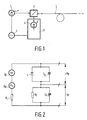
- the transmission beam from the laser diode 1 is directed via the beam splitter 2 into the optical fiber 3 to be measured. Parts of the transmitted beam which are scattered back from the LWL 3 are directed by the beam splitter 2 onto the receiver diode (APD) 4.
- the frequency-variable signal of the oscillator 5 wobbles on the one hand the light intensity of the laser diode 1 and on the other hand is used to form a mixed signal in the receiving and evaluating device 6.
- a series circuit consisting of an ohmic resistor R P and a capacitor C P is connected in series with the APD 4, which has an intrinsic capacitance C D.
- the sum voltage from the direct voltage U G and the modulation voltage U M proportional to the signal of the oscillator 5 is applied to the series circuit.
- the internal resistance of the two voltage sources is denoted by R i .
- the laser diode 1 is modulated and swept through the frequency f o to f max in a time T by means of the oscillator 5.
- the power of the transmission beam then changes according to the following equation: P (t) P ⁇ [1 + m L cos ( ⁇ c t + t2)]
- the bias of the APD is modulated at high frequency by a signal derived from the laser diode control.
- the APD is therefore used for reception and mixing at the same time.
- the components of the circuit according to FIG. 2 were dimensioned taking the following requirements into account: - In the range of the modulation frequencies [f o , f max ] the resistance should be R »1 / ⁇ C. - in the range [f o , f max ],
- This dimensioning ensures that the modulation voltage is applied to the APD with a low resistance, while the resistance R p occurs as a conversion resistance for the signals with the mixed frequency ⁇ f and can be chosen to be large.
- i ph (t) S ⁇ M (t)
- P s (t) S ⁇ RP ⁇ M o ⁇ 1 ⁇ 2m
- the spatial resolution is accordingly if v g is the speed of light in the optical fiber.
- the spatial resolution is therefore determined by the frequency range that runs through it.
- N 5000 measuring points must be recorded.
- a Teit T of approximately 1 s should be chosen.
- the measurement time can be reduced by a factor of 10.
- the mixed signal can also be sampled, specifically for the selected example according to FIG. 2 at 10 kHz. After the measuring time T, the samples are subjected to a fast Fourier transformation. This enables a very short total measuring time to be achieved.
Landscapes
- Physics & Mathematics (AREA)
- Optics & Photonics (AREA)
- Chemical & Material Sciences (AREA)
- Analytical Chemistry (AREA)
- General Physics & Mathematics (AREA)
- Optical Radar Systems And Details Thereof (AREA)
- Investigating Or Analysing Materials By Optical Means (AREA)
- Testing Of Optical Devices Or Fibers (AREA)
Applications Claiming Priority (2)
| Application Number | Priority Date | Filing Date | Title |
|---|---|---|---|
| DE3743678 | 1987-12-23 | ||
| DE19873743678 DE3743678A1 (de) | 1987-12-23 | 1987-12-23 | Optisches rueckstreumessgeraet |
Publications (2)
| Publication Number | Publication Date |
|---|---|
| EP0322077A2 true EP0322077A2 (fr) | 1989-06-28 |
| EP0322077A3 EP0322077A3 (fr) | 1990-07-18 |
Family
ID=6343339
Family Applications (1)
| Application Number | Title | Priority Date | Filing Date |
|---|---|---|---|
| EP88202965A Withdrawn EP0322077A3 (fr) | 1987-12-23 | 1988-12-19 | Dispositif de rétrodiffusion optique |
Country Status (4)
| Country | Link |
|---|---|
| US (1) | US4957365A (fr) |
| EP (1) | EP0322077A3 (fr) |
| JP (1) | JPH01207642A (fr) |
| DE (1) | DE3743678A1 (fr) |
Cited By (1)
| Publication number | Priority date | Publication date | Assignee | Title |
|---|---|---|---|---|
| FR2738430A1 (fr) * | 1990-09-21 | 1997-03-07 | Alsthom Cge Alcatel | Procede et dispositif de transmission d'information sur fibre optique avec detection et/ou localisation d'intrusion |
Families Citing this family (6)
| Publication number | Priority date | Publication date | Assignee | Title |
|---|---|---|---|---|
| DE4231856A1 (de) * | 1992-09-23 | 1994-03-31 | Siemens Ag | Verfahren zur Fehlerlokalisierung und Reparatur in einem Lichtwellenleiternetz |
| DE4438786A1 (de) * | 1994-10-19 | 1996-05-02 | Siemens Ag | Prüfverfahren und Prüfvorrichtung für eine optische Sendeeinheit |
| US6052190A (en) * | 1997-09-09 | 2000-04-18 | Utoptics, Inc. | Highly accurate three-dimensional surface digitizing system and methods |
| DE10235562A1 (de) | 2002-08-03 | 2004-02-19 | Robert Bosch Gmbh | Verfahren und Vorrichtung zur optischen Distanzmessung |
| IL279954B (en) | 2018-07-04 | 2022-08-01 | Ariel Scient Innovations Ltd | Method and system for determining grating perturbation by modulated light |
| JP7711063B2 (ja) * | 2019-12-20 | 2025-07-22 | アリエル サイエンティフィック イノベーションズ リミテッド | 光信号から情報を抽出する方法及びシステム |
Family Cites Families (2)
| Publication number | Priority date | Publication date | Assignee | Title |
|---|---|---|---|---|
| JPS55125427A (en) * | 1979-03-23 | 1980-09-27 | Kokusai Denshin Denwa Co Ltd <Kdd> | Method of measuring breaking position of optical |
| DE3236300A1 (de) * | 1981-10-13 | 1983-04-28 | Siemens AG, 1000 Berlin und 8000 München | Faseroptische sensorvorrichtung |
-
1987
- 1987-12-23 DE DE19873743678 patent/DE3743678A1/de not_active Withdrawn
-
1988
- 1988-12-12 US US07/283,413 patent/US4957365A/en not_active Expired - Fee Related
- 1988-12-19 EP EP88202965A patent/EP0322077A3/fr not_active Withdrawn
- 1988-12-23 JP JP63325703A patent/JPH01207642A/ja active Pending
Cited By (1)
| Publication number | Priority date | Publication date | Assignee | Title |
|---|---|---|---|---|
| FR2738430A1 (fr) * | 1990-09-21 | 1997-03-07 | Alsthom Cge Alcatel | Procede et dispositif de transmission d'information sur fibre optique avec detection et/ou localisation d'intrusion |
Also Published As
| Publication number | Publication date |
|---|---|
| EP0322077A3 (fr) | 1990-07-18 |
| JPH01207642A (ja) | 1989-08-21 |
| US4957365A (en) | 1990-09-18 |
| DE3743678A1 (de) | 1989-07-06 |
Similar Documents
| Publication | Publication Date | Title |
|---|---|---|
| EP0193242B1 (fr) | Réflectomètre optique à domaine de temps avec réception hétérodyne | |
| DE10006493C2 (de) | Verfahren und Vorrichtung zur optoelektronischen Entfernungsmessung | |
| EP1529194B1 (fr) | Procede et dispositif de mesure optique de distance | |
| EP3867974B1 (fr) | Antenne de réception térahertz multicanaux photoconductrice, récepteur, système térahertz et procédé térahertz | |
| CH661794A5 (de) | Vorrichtung zur abstandsbestimmung und verfahren zu deren betrieb. | |
| DE102009055445A1 (de) | Verfahren und Vorrichtung zur Ermittlung der Position eines Kolbens eines Kolbenzylinders mit Mikrowellen | |
| DE10297037T5 (de) | Ausbreitungsmessvorrichtung und Ausbreitungsmessverfahren | |
| DE60307260T2 (de) | Verfahren und vorrichtung für die laservibrometrie | |
| EP0238134A2 (fr) | Réflectomètre à domaines optiques dans le temps avec réception-hétérodyn | |
| EP0322077A2 (fr) | Dispositif de rétrodiffusion optique | |
| EP0244883B1 (fr) | Procédé de saisissage de données par ligne de transmission utilisant des capteurs optiques | |
| EP1233256B1 (fr) | Procédé et dispositif de mesure de la dispersion chromatique d'une section de transmission optique | |
| DE3703116A1 (de) | Verfahren zur stoersignalreduktion in messaufbauten zur untersuchung von emissions- oder transmissionsprozessen | |
| EP0362474B1 (fr) | Détecteur d'avertissement pour laser | |
| DE4427352C1 (de) | Verfahren zur hochauflösenden Abstandsmessung mittels FMCW-Laser-Radar | |
| EP1251363A2 (fr) | Procédé de traitement d'un signal de fréquence | |
| DE10350489B4 (de) | Optischer Sensor | |
| DE10044690B4 (de) | Verfahren und Vorrichtung zur Messung von Entfernungen und/oder Geschwindigkeiten durch Laserpulse | |
| DE19849585C2 (de) | Vorrichtung und Verfahren zur Bestimmung der Fluoreszenz einer Probe | |
| CH596559A5 (en) | Electro=optical distance measuring device with modulated light source | |
| DE4006690C2 (de) | Verfahren und Anordnung zur Messung der Geschwindigkeit einer bewegten Oberfläche mittels eines von einem Laser ausgehenden Meßlichtstrahls | |
| DE60118352T2 (de) | Terahertz-sendeempfänger und diesen verwendende verfahren zur emission und detektion von terahertz-pulsen | |
| DE4300853C2 (de) | Verfahren zur spektroskopischen Bestimmung des Stickstoffoxidgehalts | |
| DE3246928A1 (de) | Anordnung zur bestimmung und ortung von reflexionsstellen in lichtleitenden objekten | |
| DD250588A1 (de) | Optischer impulsdetektor |
Legal Events
| Date | Code | Title | Description |
|---|---|---|---|
| PUAI | Public reference made under article 153(3) epc to a published international application that has entered the european phase |
Free format text: ORIGINAL CODE: 0009012 |
|
| AK | Designated contracting states |
Kind code of ref document: A2 Designated state(s): DE FR GB IT |
|
| PUAL | Search report despatched |
Free format text: ORIGINAL CODE: 0009013 |
|
| AK | Designated contracting states |
Kind code of ref document: A3 Designated state(s): DE FR GB IT |
|
| STAA | Information on the status of an ep patent application or granted ep patent |
Free format text: STATUS: THE APPLICATION IS DEEMED TO BE WITHDRAWN |
|
| 18D | Application deemed to be withdrawn |
Effective date: 19910121 |