EP0322375A2 - Verfahren und mit einem Mikroprozessor ausgestattete Vorrichtung zur Messung von Umweltgeräuschverschmutzung - Google Patents
Verfahren und mit einem Mikroprozessor ausgestattete Vorrichtung zur Messung von Umweltgeräuschverschmutzung Download PDFInfo
- Publication number
- EP0322375A2 EP0322375A2 EP88830545A EP88830545A EP0322375A2 EP 0322375 A2 EP0322375 A2 EP 0322375A2 EP 88830545 A EP88830545 A EP 88830545A EP 88830545 A EP88830545 A EP 88830545A EP 0322375 A2 EP0322375 A2 EP 0322375A2
- Authority
- EP
- European Patent Office
- Prior art keywords
- noise
- signal
- nuisance
- level
- input
- Prior art date
- Legal status (The legal status is an assumption and is not a legal conclusion. Google has not performed a legal analysis and makes no representation as to the accuracy of the status listed.)
- Withdrawn
Links
Images


Classifications
-
- G—PHYSICS
- G01—MEASURING; TESTING
- G01H—MEASUREMENT OF MECHANICAL VIBRATIONS OR ULTRASONIC, SONIC OR INFRASONIC WAVES
- G01H3/00—Measuring characteristics of vibrations by using a detector in a fluid
- G01H3/10—Amplitude; Power
- G01H3/14—Measuring mean amplitude; Measuring mean power; Measuring time integral of power
Definitions
- This invention relates to a method and a microprocessor-based apparatus for directly measuring the noise using a particular nuisance index associated to two physical parameters of the noise, namely the average energy level of the noise and the noise fluctuation level.
- Two different aspects in the evaluation of the environmental noise are provided. The first one is objective and relates to the physical measurement of the noise, the second one is subjective and is bound to the difficulty of defining an appropriate nuisance index considering the reactions of people to the noise. While the physical measurement of the noise is currently carried out without excessive difficulty, the subjective aspect of the noise does not allow one definitive solution to be achieved.
- the objective parameters of the noise as the intensity, the fluctuation, the level of the background noise, the characteristic of the single sound sources, also all factors of psycho-sociological nature and contingent character which can affect the response of the individual to the noise.
- the noise parameter processing is effected almost by means of the physical data of the noise, the reliability of which is evaluated by calculating the statistical correlation factor between the objective noise data and the subjective response of people according to suitable evaluation criteria.
- the index L DI (nuisance level of the noise) proposed by the present inventors some years ago (Cannelli G.B., Santoboni S., "Direct measurement of Noise Nuisance by the New Index L DI , Applied Acoustics, 7, 47 (1974).) is correlated to two essential characters of the nuisance caused by the noise: the first one is bound to the sound intensity, the second one to the noise fluctuations. It can be directly measured by means of an analogical apparatus built by the same inventors (Cannelli G.B., Santoboni S., Apparatus for directly measuring the nuisance index L DI , Technical Report No. 34, IDAC (CNR), 1975).
- the above mentioned analogical apparatus does not allow the measurement of index L DI to be effected by a single operation for a period of time greater than some tens of seconds due to problems caused by the drift of the analogical integrators.
- the apparatus of this invention based upon a microprocessor allows the above cited inconvenient to be eliminated so that uninterrupted measurements from a few seconds to over 30 minutes can be effected assuring a further extension of the time pursuant to the improving of the digital technique.
- Such apparatus is generally based on the following known concept of "nuisance level L DI ⁇ which has been already introduced by the same inventors.
- L E indicates the "average energy level” of the noise and L ⁇ is the "noise fluctuation level".
- T is the measuring time of the acoustical event in seconds;
- L(t) is the instantaneous noise level;
- K is a constant correlated with the physical data of the noise and subjective tests of evaluation of the nuisance;
- ⁇ is the prefixed time interval for the L ⁇ measurement which in the analogical apparatus was indicated as “sampling time”;
- L p (t) and L(t) are the noise levels relative to a small time constant (noise fluctuation) and a greater time constant (average noise level), respectively;
- n is a whole number depending upon the minimum dB-range of the noise fluctuation one wants to detect.
- the nuisance components L E as determined above is the time calculated average value of the noise intensity expressed in logaritmic scale.
- the component L ⁇ is the nuisance portion due to the noise fluctuations.
- the constant ⁇ is provisionally reduced to unit in the digital apparatus.
- index L ⁇ accounts for the behaviour of the human ear under certain noise conditions. In particular the contribute to the nuisance is only due to the positive noise fluctuations with respect to the average value. Further the index L ⁇ accounts not only for the istantaneous noise fluctuations but also for the recent history of the noise as the nuisance sensation depends also on the temporary custom of the listener to the noise level immediately preceding the noise fluctuation.
- index L DI is a physical parameter approximating as much as possible a psycho-physiological aspect of the nuisance caused by the noise. It is in fact known that a fluctuating noise sensed after a long enough silence interval causes a nuisance sensation greater than that of a noise having fluctuations of the same magnitude and statistical distribution but sensed immediately after a background noise which is so loud as to considerably raise the threshold level of the human ear sensitivity.
- the apparatus of this invention is comprised of a microphone feeding the received signal to a pre-amplifier which applies this signal to a RMS-detector provided with a small time constant.
- the output of said detector drives a 8-bit analogical-to-digital converter associated to a timer.
- the converter supplies the signal both to a digital filter acting as a RC-circuit having a long time constant and one input of a comparator.
- Said filter feeds an output signal both to the other input of said comparator and an integrator which supplies the parameter L E to a display unit.
- the multiple threshold comparator feeds an output signal to suitable store registers associated to a timer and providing the parameter L ⁇ which is displayed by the aforesaid display unit.
- a noise receiving microphone which supplies an electrical signal to a pre-amplifier 1 feeding in turn its output signal to a RMS-detector 2 provided with a short time constant.
- the output signal of detector 2 drives a 8-bit analogical-to-digital converter 3 associated to a timer 4.
- the output signal of converter 3 is applied both to a digital filter 5 acting as a RC-circuit having a long time constant and to one input of comparator 6.
- Section I is comprises of blocks 1, 2, 3 and 4 formed of properly designed electronic circuits providing a preliminary processing of the analogical signal and the requested analogical-to-digital conversion in order to successively carry out the digital signal processing.
- Blocks 5 to 10 of section II related to the digital signal processing and perform the logical functions providing the synthesis of the whole data processing and the displaying of final results as well.
- section II has been designed as an electronic system provided with a microprocessor card implementing a suitable software performing the desired logical functions.
- CMOS technology devices which allow portable battery-powered apparatus to be provided due to low power consumption.
- the signal from microphone M is properly amplified by block 1 and is fed to RMS-detector 2 provided with a short integration time constant ⁇ 1.
- the output signal of detector 2 is subjected to analogical-to-digital conversion by block 3 also performing the interfacing function of its output signal with block 5 of section II.
- the first section is also provided with block 4 which performs the clock function and synchronizes the sampling circuit and the interface of block 3.
- the 8-bit analogical-to-digital converter 3 is adapted to cover a dynamic of about 46 dB which is considered wide enough because the conversion is carried out after the filtering operation of block 2 having a time constant ⁇ 1.
- the dynamic of the signal therefore, is strongly reduced with respect to the input signal of the microphone.
- the digital signal is then processed by a digital filter (block 5) which is able to act as a RC-circuit having a high time constant.
- the output signal of the digital filter 5 is integrated by means of summing operations in a store register (block 7) so as to provide the component L E of the index L DI .
- This component is then supplied to a display unit 9 providing a readout for the operator.
- the calculation of the component L ⁇ is carried out by means of a comparator 6 and counters 8.
- the multiple threshold comparator 6 compare the two signals, i.e. the low time constant signal (which is the digital input signal of the digital filter 5) and the high time constant signal (which is the output signal of the digital filter 5).
- the thresholds of comparator 6 spaced from one another by 3 dB are four so as to cover a dynamic range of 12 dB.
- the output signals of comparator 6 (one for each threshold) are fed to as many counters 8.
- the total sum of the counting operation is then fed, except for a conversion factor, to the display unit 9 providing the desired component L ⁇ .
- the programmable timer 10 determines the total time interval for the measurement.
- Fig. 2 shows the diagram of the input amplifier 1. It is formed of two operational amplifiers using input JFET TIL 081. The first amplifier is connected so as to have a voltage gain of about 10 dB and an input impedance of 47 kOhm.
- the second operational amplifier which is connected to the first stage over a trimming resistance to adjust the gain upon calibrating the apparatus, is used as impedance matching unit to provide a suitable coupling with RMS-detector 2 which requires as drive stage a low inner impedance generator.
- the gain of the amplifier needs a pre-amplified microphone M adapted to provide output voltages of about 1 V eff .
- a sound level meter can be used by picking up the signal from its standard "AC" output.
- the circuit diagram of the root mean square detector (block 2) is shown in Fig. 3. This function is performed by only one integrated circuit AD536A which is adapted to assure its operation for an useful input dynamic range of 60 dB with a precision better than one percent over 40 dB for signals having a crest factor up to 7.
- a trimmer which is formed of a potentiometer of 50 kOhm and a voltage divider consisting of two resistance of 470 kOhm and 249 kOhm, respectively.
- a further input trimming resistance allows a precise adjustment of the scale factor which can be effected by the offset compensation network.
- the capacitor set C1 consists of three components with values of O.4 ⁇ F, 4 ⁇ F and 40 ⁇ F corresponding to 10 ms, 100 ms and 1 s, respectively.
- the circuit can be preset according to said time constants to measure fast, middle or slow noise fluctuations, respectively.
- the capacitor set C2 also consisting of three components with values of 1 ⁇ F, 10 ⁇ F and 100 ⁇ F, respectively, allows the residual ripple to be reduced without impairing the settling time of RMS-detector 2.
- the value of C2 is selected according to that of C1 so that C2 is equal to about 2C1.
- the output signal of the detector (block 2) is successively converted into digital form by the 8-bit A/D converter 3 (Fig. 4).
- Converter 3 consists of only one integrated circuit AD 673 including the basic typical functions of a device constructed according to the successive approximation technique: a comparator, a D/A converter and a shift register (SAR).
- the A/D converter 3 even if with only 8 bit, has a sufficient input dynamic (about 46 dB) as its input signal is fed from a low-pass filter of RMS-detector 2.
- the cutout frequency relative to such a filtering operation is 100 Hz
- the minimum theoretical sampling frequency is 200 Hz, such a value being increased to 250 Hz for safety reasons.
- the conversion time of the device according to the manufacturer's specification is lower than or equal to 30 ⁇ s. As the conversion rate with respect to the low passing band of the analogical signal is high, a sample and hold circuit is not needed any longer, thus simplifying the whole system.
- the converter provides only one pulse control signal which establishes the beginning of each A/D conversion operation.
- the sampling frequency is established by the repeating frequency of the control pulse (block 3) generated by the integrated circuit NE 555.
- the digital signal is available directly in 8-bit parallel form at the output of the converter which is provided with an inside buffer and does not require any additional circuit for the interfacing with the outside.
- the parallel output is than simply connected to an output connector 11 along with a ninth bit, said connector being inserted into converter AD 673 providing the signal of end of conversion, i.e. "output data ready".
- the parallel interface allows the outer microprocessor to be directly connected provided that said microprocessor is provided in turn with a parallel interface.
- a parallel/serial protocol converter compatible with the standard interface RS 232.
- the circuit is simply comprised of a shift register 54C 165 and two fli-flops of D-type driven by suitable strobe signals and clock signals generated by auxiliary circuits formed of further two integrated circuit NE 555.
- a transistor 2N 2907 makes the logical voltage levels compatible with those of the standard interface RS 232.
- the use of a serial interface 12 is possible as the provided sampling frequency is low (250 Hz), thus allowing data transfer in real time also over this connection. However, as it is convenient using the maximum data transfer rate, the serial interface operates with at least 9600 baud, preferably it is provided a higher rate of 19200 baud to be used if the employed microprocessor can operate accordingly.
- the parallel interfacing is the only one that allows the most operation in real time to be carried out by the microprocessor between samplings in succession. If the developed software provides operations of this type the use of a parallel interface becomes compulsory.
- the auxiliary circuits for the generation of the sampling frequency, the clock signal for the serial interface and the strobe signal provided by a monostable multivibrator from the sampling frequency are formed of simple oscillators which are not crystal-controlled as the requested precision and stability are not so high (about 1%).
- a final auxiliary circuit is the power supply.
- the voltages requested by the above described circuits are 5 volts and ⁇ 15 volts.
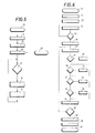
- section II of Fig. 1 and the software requested to implement the functions described in section II of the block diagram is concerned, instead of a particular language listing for a determined microprocessor system it is preferable to give a functional description of general utilization by means of flow charts, thus providing the general criteria to properly develop a software apart from the employed system.
- This further allows the increasing of the available memory as well as of the data processing rate of the central processing unit to be utilized in the best way, said capabilities being the main features which are more and more improved with the increase of the efficiency of the portable microprocessor systems. This is true in particular for the portable systems which still needs a considerable improvement with respect to the stationary systems, especially in terms of cost to efficiency ratio.
- a first function of the microprocessor system relates to the acquisition of digital data from the analogical-to-digital converter 3. Such data are stored in the RAM of the microprocessor and this can be made according to two different strategies:
- the measurement time interval is in any case determined by a timer which can be constituted by the clock of the system suitably programmed by the control software. The clock generates interrupt signals which cause the central processing unit to stop the acquisition process.
- the "data ready" signal for the CPU to be received from A/D converter 3 can be generated either by polling techniques or by interrupt techniques, the latter being almost compulsory in case of data processing in real time.
- the subsequent data processing consists of the digital filtering to obtain an integrated signal according to the longer time constant, comparing the levels having a short time constant with the level having the long time constant and calculating L E and L ⁇ by using suitable counting registers.
- the final value of L E al L ⁇ is then fed to display 9 of the employed microprocessor.
- the flow chart of Fig. 6 shows the logical sequence to be performed in order to carry out the above described operations. It should be noted that in the first time period of two seconds corresponding to the first 500 samples an initial value of the level relative to the long time constant is calculated without any calculation relative to L E and L ⁇ .
- blocks 21 to 40 indicates the following steps
Landscapes
- Physics & Mathematics (AREA)
- General Physics & Mathematics (AREA)
- Measurement Of Mechanical Vibrations Or Ultrasonic Waves (AREA)
Applications Claiming Priority (2)
| Application Number | Priority Date | Filing Date | Title |
|---|---|---|---|
| IT4874487 | 1987-12-23 | ||
| IT8748744A IT1211995B (it) | 1987-12-23 | 1987-12-23 | Metodo e strumento a microprocessore per la misura diretta di un particolare indice per la valutazione del rumore ambientale |
Publications (2)
| Publication Number | Publication Date |
|---|---|
| EP0322375A2 true EP0322375A2 (de) | 1989-06-28 |
| EP0322375A3 EP0322375A3 (de) | 1991-07-03 |
Family
ID=11268358
Family Applications (1)
| Application Number | Title | Priority Date | Filing Date |
|---|---|---|---|
| EP19880830545 Withdrawn EP0322375A3 (de) | 1987-12-23 | 1988-12-20 | Verfahren und mit einem Mikroprozessor ausgestattete Vorrichtung zur Messung von Umweltgeräuschverschmutzung |
Country Status (4)
| Country | Link |
|---|---|
| US (1) | US5072415A (de) |
| EP (1) | EP0322375A3 (de) |
| JP (1) | JPH01232222A (de) |
| IT (1) | IT1211995B (de) |
Cited By (3)
| Publication number | Priority date | Publication date | Assignee | Title |
|---|---|---|---|---|
| DE4228934A1 (de) * | 1992-08-31 | 1993-01-07 | Alios Dipl Phys Dr Heiss | Verfahren zur bestimmung des vertrauensbereichs von perzentil-messwerten kontinuierlicher stochastischer schallsignale |
| DE102004016184A1 (de) * | 2004-03-30 | 2005-11-03 | Beyer Dynamic Gmbh & Co | Verfahren zur Vermeidung von Hörschäden und Gehörschutzeinrichtung |
| WO2007023017A1 (de) * | 2005-08-25 | 2007-03-01 | Robert Bosch Gmbh | Verfahren und vorrichtung zur bewertung der lästigkeit von quietschgeräuschen |
Families Citing this family (9)
| Publication number | Priority date | Publication date | Assignee | Title |
|---|---|---|---|---|
| JPH05256951A (ja) * | 1991-12-09 | 1993-10-08 | Forschungszentrum Juelich Gmbh | 半導体検出器の信号をデジタル処理する回路装置 |
| US5420581A (en) * | 1993-05-26 | 1995-05-30 | Bodysonics, Inc. | Maternal sound level device and method for protecting fetal hearing |
| ES2107360B1 (es) * | 1995-01-10 | 1998-07-01 | Proceso Digital De Audio S L | Un sonografo. |
| US6704428B1 (en) * | 1999-03-05 | 2004-03-09 | Michael Wurtz | Automatic turn-on and turn-off control for battery-powered headsets |
| GB2349466B (en) * | 1999-04-27 | 2003-10-15 | Mitel Corp | Method for noise dosimetry in appliances employing earphones or headsets |
| US7457750B2 (en) | 2000-10-13 | 2008-11-25 | At&T Corp. | Systems and methods for dynamic re-configurable speech recognition |
| US6826515B2 (en) * | 2002-02-01 | 2004-11-30 | Plantronics, Inc. | Headset noise exposure dosimeter |
| US20050100169A1 (en) * | 2003-11-10 | 2005-05-12 | Kenneth Shelley | Automotive gauge-based sound pressure instrument |
| US10228397B2 (en) * | 2015-11-20 | 2019-03-12 | Keysight Technologies, Inc. | Apparatus and associated methods for monitoring noise level of a signal |
Family Cites Families (7)
| Publication number | Priority date | Publication date | Assignee | Title |
|---|---|---|---|---|
| US3747703A (en) * | 1971-01-18 | 1973-07-24 | Minnesota Mining & Mfg | Noise exposure computer and method |
| US3778552A (en) * | 1972-09-27 | 1973-12-11 | Shell Oil Co | Personal sound monitor |
| US3848471A (en) * | 1973-04-23 | 1974-11-19 | Gen Motors Corp | Noise pollution level measuring circuit |
| US3892133A (en) * | 1973-09-13 | 1975-07-01 | Us Transport | Statistical sound level analyzer |
| US4020286A (en) * | 1975-05-19 | 1977-04-26 | Metrosonics, Inc. | Signal analysis apparatus for amplitude statistics |
| US4307385A (en) * | 1978-11-22 | 1981-12-22 | Sue Ann Evans | Noise monitoring apparatus |
| US4554639A (en) * | 1983-04-06 | 1985-11-19 | E. I. Du Pont De Nemours And Company | Audio dosimeter |
-
1987
- 1987-12-23 IT IT8748744A patent/IT1211995B/it active
-
1988
- 1988-12-16 US US07/285,443 patent/US5072415A/en not_active Expired - Fee Related
- 1988-12-20 EP EP19880830545 patent/EP0322375A3/de not_active Withdrawn
- 1988-12-23 JP JP63325752A patent/JPH01232222A/ja active Pending
Cited By (4)
| Publication number | Priority date | Publication date | Assignee | Title |
|---|---|---|---|---|
| DE4228934A1 (de) * | 1992-08-31 | 1993-01-07 | Alios Dipl Phys Dr Heiss | Verfahren zur bestimmung des vertrauensbereichs von perzentil-messwerten kontinuierlicher stochastischer schallsignale |
| DE102004016184A1 (de) * | 2004-03-30 | 2005-11-03 | Beyer Dynamic Gmbh & Co | Verfahren zur Vermeidung von Hörschäden und Gehörschutzeinrichtung |
| DE102004016184B4 (de) * | 2004-03-30 | 2008-06-26 | Beyer Dynamic Gmbh & Co | Verfahren zur Vermeidung von Hörschäden und Gehörschutzeinrichtung |
| WO2007023017A1 (de) * | 2005-08-25 | 2007-03-01 | Robert Bosch Gmbh | Verfahren und vorrichtung zur bewertung der lästigkeit von quietschgeräuschen |
Also Published As
| Publication number | Publication date |
|---|---|
| US5072415A (en) | 1991-12-10 |
| IT8748744A0 (it) | 1987-12-23 |
| EP0322375A3 (de) | 1991-07-03 |
| JPH01232222A (ja) | 1989-09-18 |
| IT1211995B (it) | 1989-11-08 |
Similar Documents
| Publication | Publication Date | Title |
|---|---|---|
| CA1182530A (en) | Neuromuscular block monitor | |
| US4665926A (en) | Method and apparatus for measuring the relaxation state of a person | |
| EP0122074B1 (de) | Audio-Dosismesser | |
| EP0322375A2 (de) | Verfahren und mit einem Mikroprozessor ausgestattete Vorrichtung zur Messung von Umweltgeräuschverschmutzung | |
| US4461301A (en) | Self adjusting bio-feedback method and apparatus | |
| US6392402B1 (en) | High crest factor rms measurement method | |
| US20020099306A1 (en) | Stimulus analysis system and method having adaptive artifact rejection | |
| JPH07128414A (ja) | バッテリ試験装置及び同試験装置を内蔵した電力装置 | |
| KR20000060280A (ko) | 라플라스 변환 임피던스 측정방법 및 측정장치 | |
| US5296856A (en) | Window tracking ADC | |
| US3747703A (en) | Noise exposure computer and method | |
| US4540000A (en) | Signal conditioner for biological signals | |
| EP0043569A2 (de) | Elektromyograph zum Darstellen von Kaubewegungen | |
| US5003983A (en) | Cardiac monitoring system | |
| US4283678A (en) | Cable condition analyzing system for electric arc furnace conductors | |
| CN114325462B (zh) | 一种usb充电设备智能检测设备及方法 | |
| US3884086A (en) | Audio dosimeter | |
| Zaid et al. | Detection and classification of short and long duration disturbances in power system | |
| US3977257A (en) | Audio dosimeter | |
| JPH05212006A (ja) | 心拍間隔計測装置 | |
| US4103750A (en) | Method of and circuit for forming signals for damping control of an electrical measured-value indicator | |
| Bernard | Leq, SEL: When? Why? How? | |
| JPH07198807A (ja) | 電池残量算出装置 | |
| JP3321966B2 (ja) | 時間比率検出回路 | |
| US3995622A (en) | Device for determining changed pulses |
Legal Events
| Date | Code | Title | Description |
|---|---|---|---|
| PUAI | Public reference made under article 153(3) epc to a published international application that has entered the european phase |
Free format text: ORIGINAL CODE: 0009012 |
|
| AK | Designated contracting states |
Kind code of ref document: A2 Designated state(s): AT BE CH DE ES FR GB GR LI LU NL SE |
|
| PUAL | Search report despatched |
Free format text: ORIGINAL CODE: 0009013 |
|
| AK | Designated contracting states |
Kind code of ref document: A3 Designated state(s): AT BE CH DE ES FR GB GR LI LU NL SE |
|
| 17P | Request for examination filed |
Effective date: 19911118 |
|
| 17Q | First examination report despatched |
Effective date: 19921208 |
|
| STAA | Information on the status of an ep patent application or granted ep patent |
Free format text: STATUS: THE APPLICATION IS DEEMED TO BE WITHDRAWN |
|
| 18D | Application deemed to be withdrawn |
Effective date: 19930701 |